Note: Descriptions are shown in the official language in which they were submitted.
2107~12
i~l)R~ULIC ~EVICE F~ U~E IJi J~ UCTI~l~J Mh~C~
CR-JSSREFERENCE TC~_RELhTE~ hPPLICAI~NS
This appl ication claims the priority of German Patent
Application No. 4234647.9, filed Octo~er 14, l9g2, which is
incorporated herein by reference.
BAC~ JUN~ GF THE INVENTION
1. Fieid of the Invention
This invention reiates to a hydraulic device for
hydraulic consumers for use in a production machine,
particularly in an injection molding machine for processing
syntnetic materials or comparabie plastic or plastifiabie
masses, comprising at least one control valve with at least
three c,ont,rol positions, the control valve being regulabie
by at ieast one transducing means associated to a supply
line by comparison of actual values with preset nominal
values programmable in a control unit, whereby a variable
capacity pump feeds consumers with fluid via the supply
line ieading over the control valve. The hydraulic device
furthermore comprising a back flow pipe and a feedback line
connecting a controlling device of the variable capacity pump
with the supply line downstream of the control valve with the
purpose of adjusting the pump output so as to rnaintain a
constant operation~l pressure gradient,
2~7~12
2. ~.escI-iptior, of t~ Prior Art
A hydraulic device of this kind is disclosed
in German Patent 31 19 095. In this device the energy
consumption of the variable capacity purnp is adapted to
the respective power requirements of a lower limit, by
chosing as a basis for the operation and the control a just
sufficient constant operational pressure gradient,
presettable at the controlling device of the variable
capacity pump. On the other hand the known control device
meets the e~tremely different operational conditions, since a
quaniity - or pressure adjustment diverging from the nominal
value preset of the control valve is feedbackable
alternatively by rrleans of pressure transducers, distance
detectors or distance potential transformers to the nominal
value in the contr~l circuit. However, such an appliance only
can influence the afflux side of the consumer.
A further hydraulic device is known from US
Patent 4,823,551. In this device the supply lines are
alternatively in connection with a common feedback line by
2~ mean~ of a shuttle valve. The branch supply line naving an
inferior pressure is provided with a controller for a fully
~tabilization of a nominal value deviation of the feeding
current conditioned by a pressure asymmetry. Certainly this-
way a simultaneous supply of several hydraulic consumers by
the varia~le capacity pump is pos~ible, however, also in this
-- 2 --
" , . . . .
2~7~2
ca.se orlly the afflu~. side of the c-,r,sumers is influenceable,
US Patent 5,1~,8~6 di~closes a hydraulic device
fGr a consumer provided with a ~/4-way vaive, adapted tO
effect a differential switching, ma~ir.g possible a feeding of
the pressure line with fluid ousted by the consumer via a
derived circuit provided with a nonreturn valve. In fact the
discharge of the fluid can be effected by a overlying
pressure regulation, however, the expenditure involved is
considerable, since each a separate control valve has to be
associated to each consumer.
SUMMA~Y OF THE INVENTION
It is an object of the invention so to design
a hydraulic device which is of the kind described first
hereinbefore, so that a precise and energy saving regulation
or control of the consumers in both directions of flow
transferred can be effected by a control valve at a
reasonable price.
That object is accomplished in accordance with
the invention in that the back flow pipe is also conducted
via a control valve and the consumers are connected with the
control valve by means of connecting valves, each of them
associated to one of said consumers. Furthermore, at least
one tran~ducing means is associated to the back flow pipe,
which in connection with the first transducing means of the
~upply line constitutes a regulating variable for the control
unit,
2~7~12
Such an arr~ngemerlt offers the advantage th~ the
r~specti~e consumers do not need a direction valve, ~ince the
physical variables velocity or number of revolutions,
position, pressure or force, are controlled or regulated ir.
both directions of flow transferred. The consurners are merely
connected by means of connecting valves thus allowing a
simple control being at the same time easy to maintain. Since
nevertheless the afflux side as well as the reflux side can
be controlled or regulated, an improved and more comfortable
control, compared with the prior art, can be realized, in
spite of the cost reduction. Thereby the disadvantage that
~ hiqher self-oscillation conduct arises, caused by the
distance from the control valve to the consumer, which
reduces the dynamic of the control, is consciously accepted,
1~ since these effect is compensated for by the advantages
aained with it. In this arrangement no additional switching
magnets are required at further valves and the loss of
control dynamic can be partially compensated for by the
po~sibilities to influence the afflux and the reflu~.
The reduction of the number of further valves between pump
and consumer additionally leads to a diminution of the
103s of pres~ure, so that the hydraulic device still can deal
economically ~ith the energy being at its disposal. Thereby
the basic conditions for a central velocity -, pressure - and
po~ition control for the hydraulic circuit of the iniection
-- 4 --
2~07~1~
moldir~g rnachir,e are created by a superset electronic
control - or regulation device The control valve acts
together with the variable capacity pump like an afflu~
corltr-, 1 .
According to a preferred feature a respective
just catching control edge of the control valve derates the
fluid being ousted by the consumer in a discharge. Due to
this arranaement it is possible to control acceleration
and reduction of speed in case cylinders or hydromotors are
applied. Especially for positioning - respectively force
control according to the principle of hydraulic full bridge
such a construction is necessary.
According to a preferred feature further variable
capacity pumps are additionally connectable in both flow
flow directions in a connection line between the first and
further variable capacity pùmps by means of a further
connecting valve and mentioned further variable capacity
pumps together with the first variable capacity pump are
associated to several control circuits with several control
valves regulated by a control unit. Due to the application
of several variable capacity pumps connected side by side, in
such arl arrangement it is po~sible to either increase the
volume flow at one control valve in case necessary or to
provide several control - or regulation circuits in parallel,
whereby the pump capacity of the particular variable capacity
-- 5 --
21~7fj~2
pumps might partially b~ arranged in cascade, which rnakeg a
contribution to energy saving,
According to a preferred feature a reser~Gir is
feedable by the variable capacity pump via a 2/~-way valve
and a line, the reservoir being dischargeable over the line.
If in such an arrangement a reservoir is additionally
connected, volume flows momentarily not required can be
loaded in the reservoir and subsequently be discharged over
one or several control - or regulation circuits. This is
especially perceptible in an energetically favorable
operatina method, if several control circuits are connected.
Supplementarily also a high speed can be controlled by means
of the reservoir.
According to a preferred feature the control
valve is a 4/4-way valve; its forth control position
generates a differential switching for feeding the fluid
ousted by the con~umer into a pump branch, being overbridged
by the 4/4-way valve via a derived circuit provided with a
nonreturn valve. In such an arrangement a high speed can be
achieved ~ recirculat,ion of the ousted oil into the pump
br~nch in spite of an energetically favorable operating
method.
2~7~12
BRIEF DE~CRIPTION OF THE DRAWING
Figure 1 is a dia~rar~natic view of the hydraulic
device.
Figure 2 shows the hydraulic device according
to Figure 1 and the control unit when applied to an
injection molding machine for processing plastic materiais
Figure 3 shows the hydraulic device provided with
several variable capacity pumps and several control circuits.
Figure 4 shows the hydraulic device with its
associated reservoir.
Fiaure 5 shows the hydraulic device provided with
a 4/4~way valve.
DETAILE~ ~ESCRIPTION OF THE PREFERRED EMBODIMENTS
The invention will now be described in more
detail by example with reference to the embodiments shown in
the Figures. It should be kept in mind that the following
described embodiments are only presented by way of exampie
and should not necessarily be construed as limiting the
inventive concept to any particular physical configuration.
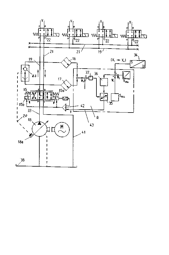
~O The hydraulic device is meant for hydraulic
consumers V. In the preferred embodiment it is used in an
injection molding machine for processing synthetic materials
or comparable plastic or plastifiable masses such as for
e~ample ceramic masses. According to Figure 1 it is provided
with a 4/3-way valve with three switching positions serving
2107612
~s control valve l5, wrlictl is at ieast ~djustable by at le~st
one first transducing means by cornparison of actual vaiue~
with preset nominal values prograrnmable in a control unit ~.,
The variable capacity pump 18 feeds the consumers V via a
supply line 19 leading over the control valve. PossiDle
consumers might for example be injection cylinders, dosing
motors, mold closing units, ejectors, core pullers or other
aggregates.
As can be seen from Figure 1 also the back flow
l~ pipe 21 is led over tne centrally arranged control valve 15.
A central arrangement of the control valve 15 is of advantage
if the friction losses on the supply lines 19 should be kept
as low as possible, The control valve is in connection with
the consumers (Fig. ~j by rneans of connecting valves 22,
each one of them assosiated to each respective consumer.
A second transducing rneans is also associated to the back
flow pipe 21. As transducing means two pressure transducers
16,17 for collection of the differential pressure, a pressure
transducer for acquisi ion of the maximum pressure in both
2G iines or one single or several transducers for registration
of the position or veiocity can be applied. Thus a quantity
is acquired that plays back the conditions on both sides of
the consumer, whereby this quantity can be acquired for both
sides together by means of only one transducing means. This
means that the transducing means provide actual values as
input quantitie~ for the control unit R. Basically pressure
-- 8 --
, ................... . . .. .
21~7~12
transducers, velocity transducers, positior csverage mean3 or
the like are provided as transducing means. According ~o the
position of the control valve the function of supply line 1g
and back flow pipe 21 is interchanged. When the control
valve is in pGsition P-A the supply line which actually
reacts is the supply line 19 and when the control valve is in
position P-B it is the back flow pipe 21 that actually
reacts.
The fluid ousted by the consumer is always
derated in the discharge by the just catching control edge
B-T respectively A-T of the control valve. The middle
control po~ition of the control valve is a stopping
position permitting a locking for example during the dwell
pressure phase of the injection molding machine. The control
valve can be either directly controlled or pilot controlled
and be provided with one or two control magnets 15a,15b.
The application of such two control magnets should be aspired
to for safety reasons. The feedback of the actual pressure
value to the controlling device 18a, 18a' of the variable
capacity pump 18,18' is effected by means of a shuttle valve
23.23'. It is also possible to alternatively provide for
e~ample way valves, control taps at the control valve or an
e~ternal pressure feeding. The feedback as well as the
adjustment of the variable displacement pump is effected in
connection with the superset electronic control unit R.
_ g _
2~076~
The reedback effect~ that the variable capacity pump 18
supplie~ a variable, impressed volume flow Ql.
Figure 3 presents an arrangement of the invention
in which a further variable capacity pump 18' with a volume
fiow Q2 is assigned to the variable capacity pump 18.
Basically the variable capacity pump 18 is determined for the
control - or regulator circuit I and the second variable
capacity pump 18' for the second control - or regulator
circuit II. Both control circuits are largely structured
identically, so that the reference characteristics of the
first control circuit, additionally provided with an
apostrophe for differentiation, are used for the elements of
the second control circuit. In the second control circuit
the consumer is supplied via the supply line 1g'and the back
~low pipe 21' is conducted over the control valve 15'. The
pressure transducers 16',17' are connected by means of the
~huttle valve 23' with the variable capacity pump 18' over
the feedback line 20'. The recycled oil gets to the tank 38
downstream of the control valves 15,15'. Both variable
Z0 capacity pumps 18, 18' are interconnected by a connection
line 3g In this line a further connecting valve 24 is
provided. According to the application desired the complete
volume flow Q2 or a partial volume flow can be additionally
connected to the volume flow Q1 of the variable capacity
pump 1~. Ho~lever, this additional connection is also possible
-- 10 --
2107~12
into the otheY direction of f low tran,sferred, so that ~otrl
control circuits, as the need arises, can be alwa,vs supplied
with the respective volume f low required. The reflux
downstream of the control valve to the tank 3~ is effected
via the lines 41,41'.
In Figure 4 a reservoir is added to the control -
or regulator circuits I and II. The Figure thereby presents a
variable capacity pump 18, regulated by the afflu~ side,
which supplies the reservoir via the line 40 and the 2/2-way
valve 26. provided that the control valve 15' is in its
middle position. The 2/2-way valve 27 is opened for filling
the reservoir and the pressure is registered by the pressure
transducer 44. As a result, if the 2/2-way valve Z7 is
closed, the control circuits I and II can be supplied by the
variable capacity pump in the way already described. As 2/~-
way vaive for example a Cartridge valve can be applied. If
the reservoir is filled, it can be discharged over the line
2~ or 40 into each of both control circuits in case
necessary. That way it is for example possible to effect a
high speed control. In order to avoid a reflux from the
reservoir 30 to the variable capacity pump during the
discharge action, a nonreturn valve 45 is provided in the
pump branch 33.
In Figure 5 a 4/4-way valve, which has a forth
control position, is used instead of a control valve, the
-- 11 --
2~7~12
rest of the construction of the hydraulic device remaining
largely identical. In this position a differential switching
is possible for feeding the fluid ousted by the consumer into
a pump branch 33, the 4/4-way valve being overbridged by a
S derived circuit 32 provided with a nonreturn valve 31. In
this way it is possible to achieve an approximately 30%
higher speed, if the operating method is favourable with
respect tG ener~etics.
Figure 2 furthermore shows the electronic
control unit R in more detail with respect to its circuits.
It works on the principle of a multivariable control system
of either analog or digital construction, At least one first
transducing means 16, however better a first and a second
transducing means 16,17, are provided for each control valve,
This transducing means transmits the actual pressure - or
force values to the pressure controller 37, which determines
the command variable W3 for the pressure - and force
regulation. The actual values for positioning xl to Xn are
ascertained in the distance potential transformer 34 and
compared with the nominal positioning value, whereby the
command variable w1 for positioning is determined. The
velocity is compared with the nominal velocity vOOll, whereby
the co~nand variable w2 for velocity is determined. The
appertaining actual values are acquired analogly or
2~ digitally ~y transducing means adapted to acquire actual
- 12 -
,. . . . . .
,
21~7~12
values. The cor~r~and variable wz for velocity or the cor~hand
varlable w is superset and the comrnand variable W3 for the
pressure - and force regulation has a lirniting effect ln the
limiting means 35 with regard to the actual positioning
variable y respectively y ,y2. Then the positioning variables
are transmitted to the comparator device 42 via the siqnal
line 43, which compares the actual position of the control
valve with the positioning variable and in case necessary
arranues for an adjusting movement of the control valve. The
iO velocity can be controlled or adjusted in the sense of
automatic control technic. The control circuit is closed
by the electronic control unit. If purely pressure - and
force r-egulation is required, also reversible controller
networks could he applied.
It will be understood that the above description
of the present invention is susceptible to various modifi-
cations, changes and adaptations, and the same are intended
to be comprehended within the meantime and range of
equivalents of the appended claims.
- 13 -
..