Note: Descriptions are shown in the official language in which they were submitted.
:-`. 2~79'~
DRIVE MOTOR INCLUDING TORQUE T~15DUCER
This invention relates to a drive motor including a
torque transducer.
Monitoring of dynamic stresses and strains in power
tools and other rotating machinery is often desirable. The
data received from such operations permit evaluation of the
performance of the equipment in question. In the case of
power tools, such as nutrunners or screwdrivers, the data
permit measurement of the torque output and thereby
calculation of fastener tension produced by the tool. Real
time feedbac~ coupled with programmable controls makes it
possible to automatically deactivate the tool power when a
desired fastener tension is achieved. This provides the
benefit of reproducible fastener tensioning in assembly line
or other mass production operations. A variety of
transducers are available for measuring torque output of
rotating machines. Most such transducers are quite
satisfactory for their intended applications; however, in
some cases the axial dimensions of the transducer are such
that their use requires an unacceptable increase in the size
of the tool. When the tool must be used in a limited space
environment, such size increases may be intolerable. In
such cases, fastener tension can only be determined by use
of tortuous tool combinations of questionable acc~racy.
In addition, an excessive increase in size can
contribute to increased weight and unwieldy proportions
which can contribute to premature operator fatigue and
otherwise degrade operator performance.
DE-A-2 317 307 discloses an assembly used to measure
the speed characteristics of a slow running motor on a test
stand and includes a planet gear in which a sun wheel is
BS'~
~-- 2~ ~77~'~
driven by a motor and motor output is transmitted through a
plurality of arms. To measure drive torque, a plurality of
thin flexible metal strips interconnect a gear housing and
part of the gear train and wire strain gauges are mounted on
the metal strips to give measurement of the torque.
US-A-4 418 590 discloses a drive unit for imparting
torque to an output shaft, a caSing housing the drive unit
being subject to such torque. An intermediate torque
transducing disc includes inner and outer portions connected
by strips, the disc slidably connecting the drive housing
and a static retainer.
US-A-4 055 080 discloses a torque apparatus that can be
retro-fitted onto a power wrench and includes a power
transmitting train with strain gauges for measuring the
torque.
PATENT ABSTRACTS OF JAPAN, Vol. lo, number 324 (P-512)
(2380), 5 Nov. 86 & JP-A-61 130 837 discloses a means for
detecting torque by interposing measuring sensors between a
casing and a stator so as to regulate the rotation of the
stator in a circumferential direction of a rotating shaft
thereof. When the shaft i5 rotated, thereby having a load
applied to it, a torque reaction force acts upon a thin
section of a sensor between the stator and a casing body and
the distortion of the thin section is detected with a strain
gaugQ .
- According to the present invention, there is provided a
drive motor including a torque transducer coupled to an
output drive train within a housing of a rotating machine,
the drive train having a floating portion with an output
axis and the torque transducer comprising a substantially
disc shaped first member rigidly connectable to a static
SlJ~3S ~ 3TVT~ S~EF~
-! 21~ 7 rl ~l~
2 a
reference member of said housing and means for sensing and
measuring torsional deflections, characterised in that a
substantially disc shaped second member is slidably coupled
to said first member and also to said floating portion,
which experiences reaction torque proportional to an output
torque, said second member being rotatably restrained with
respect to said floating portion but free to slide along the
output axis thereof and comprising an outer ring and a
central portion interconnected by a plurality of shear webs
for concentrating torsional stresses into a zone between
said outer ring and central portion for detection by said
means, said outer ring and said central portion being
respectively connected to said floating portion and said
first member.
,
W 0 92/18840 PC~rlUS92/02998
- ` 2 i ~ 1 7 9 ~
B ~IEF D ESC ~IPTIO N O F TH E D RA WIN GS
Fig. 1 is a schematic partially sectional view of the transducer of the
- present invention coupled with a planetary reduction gear in a power tool which is
fragmentarily represented;
Fig. 2 is a schematic view showing added detail of the torsion meter disk of
the present invention;
Fig. 2a is a sectional view from line A-A of Fig. 2:
Fig. 2b is a sectional view from line 13-B of Fig. 2;
Fig. 3 is a schematic electrical diagram showing the torsion measuring
bridge arrangement and indicating the signal processor and relay control unit; and
Fig. 4 is a schematic sectional view of the torque transducer assembly of
the present invention.
DETAILED DESCRIPTION
By reference to Fig. 1, many of the features of the present invention can be
seen. A representation of a portion of the housing of a power tool 100 is shown
at the juncture of a motor housing 10 and a drive housing 15. Motor shaft 11
protrudes from motor housing 10 into drive housing 15 where it terminates as a
sun gear 26 within a planet gear carrier 20. Sun gear 26 meshes with and drives
planet gear 22, which is one of three or more planet gears within the planet gear
carrier 20. Planet gear 22 precesses around ring gear 24 thereby driving planet
gear carrier 20 in rotation and~ thus, output shaft 21.
wo 92/18~40 Pcr/us92/02~9
The components of the transducer of the present invention are shown near
the right side of Fig. 1. These include reference disk 14 which is rigidly attached .
to motor housing 10 by means of reference disk fasteners 12. Torsion meter disk
16 is sl;dably engaged with reference disk 14 and with torque reaction ring 18.
Torque reaction ring 18 is a substantially floating extension of ring gear 24. Also
seen in this view, are strain gages 19 and resistors 17c and 17z which are 13sed to
zero and calibrate the strain gages, respectively. Resilient ring 33, also shownhere, is discussed below.
During operation, motor shaft 11 rotates and causes sun gear 26 to impart
rolling motion to planet gears 22. The rotating planet gears 22 trave] around ring
gear 24 thereby causing rotation of planet gear carrier 20 and consequent rotation
of output shaft 21. Any resistance to rotation by output shaft 21 is transmittedthrough planet gear carrier 20 to ring gear 24 as reaction torque. Torque reaction
ring 18, which is merely a splined extension of ring gear 24, must necessarily
experience the same reaction torque. However, torsion meter disk 16 is splined to
torque reaction ring 18 on its outside diameter and to reference disk 14 on its
inside diameter. Since reference disk 14 is rigidly secured to motor housing 10,neither reference disk 14, torsion meter disli 16, nor torque reaction ring 18 are
free to turn. The use of splined couplings between the component~ prevents
development of any extraneous bending stresses within the members, thereby
assuring that only torsional stresses will be measured. Thus, by preventing counter
rotation of ring gear 24 and torque reaction ring 18, torsion meter disk 16
experiences the ful~ reaction torque which is measured by strain gages 19. Figs. 2,
2a, and 2b illustrate further detail of the torsion meter disk of the present
inventior,. External splines 30 and internal splines 32 of torsion meter dis~; 16 act
as the coupling agents between splines 31 of reference disli 14 (shown in Fig. 4)
and torque reaction ring 18, respectively. Four shear webs 3~, defined by torsion
concentrator voids 36, provide the concentration of torsional strains which permits
WO 92/18840 ~ 7 ~ ~ Pcr/US92/02998
accurate sensing by strain gages 19. This concentration improves the sensitivityand accuracy of the strain measurements. Zero resistors 17z are also shown here.
Fig. 3, viewed in conjunction with Figs. 2, 2a, and 2b, illustrates the typical
strain gage/resistor bridge arrangement used in such applic~tions. Zero resistors
17z are used to adjust the strain gage signals under zero load conditions for a
correct reading on the output meter (not shown) and for errors in alignment and
location of strain gages 19 on shear webs 35 as well as for slight deviations inshear web area caused by slight deviations in the size of torsion concentrator voids
36. Calibration resistors 17c, shown in Figs. I and 4, are used to adj~st the output
signal from strain gages 19 at selected levels of strain within the transducer range
of operation. The output signal of the strain gage bridge is routed to the
calibrated signal processor and relay control (shown symbolically) which compares
torsional strain signals to established torque/fastener tension values and
deactivates the power switch at the desired fastener tension value.
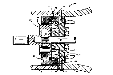
Fig. 4 illustrates further detail of the transducer assembly of the present
invention. Torsion meter disk 16 is coupled to splines 31 of reference disk 14 by
means of internal splines 32 on the torsion meter disk. Snap ring 34 retains
torsion meter disk 16 on the projection of reference disl; 14, while resilient ring 33
provides a bias of the meter disk against the snap ring. This assures that,
although torsion meter disk 16, is free to move axially under load, it cannot slide
loosely. Strain gages 19 are mounted on the axial face of torsion meter disl~ 16while resistors 17z are mounted on the inside circumference of the meter disk
within torsion concentrator voids 36. Calibration resistors 17c are mounted on the
bacl; surface of reference disk 14.
The minimum sizes for the torsion meter disk 16 and the reference disk 14
are determined by the anticipated torque range of service for the transducer
assembly and by the physical sizes of the resistors 17c and z and strain gages 19.
~'
WO 92/188~0 2 ~ Pcr/US92/0299~-~
Thus, this transducer provides the advantage of requiring a minimum volume for
installation and, conseqLlently, exerting minimum impact on the size and
configuration of the tool in which it is employed.