Language selection

Search

Patent 2108318 Summary

Third-party information liability

Some of the information on this Web page has been provided by external sources. The Government of Canada is not responsible for the accuracy, reliability or currency of the information supplied by external sources. Users wishing to rely upon this information should consult directly with the source of the information. Content provided by external sources is not subject to official languages, privacy and accessibility requirements.

Claims and Abstract availability

Any discrepancies in the text and image of the Claims and Abstract are due to differing posting times. Text of the Claims and Abstract are posted:

  • At the time the application is open to public inspection;
  • At the time of issue of the patent (grant).
(12) Patent Application: (11) CA 2108318
(54) English Title: ECCENTRICALLY SUPPORTED TOOLS FOR EXCAVATING MINERALS, COUNTERBALANCED WITH REFERENCE TO COUNTERWEIGHTS
(54) French Title: OUTILS EXCENTRES POUR L'EXCAVATION DES MINERAIS AVEC CONTREPOIDS
Status: Deemed Abandoned and Beyond the Period of Reinstatement - Pending Response to Notice of Disregarded Communication
Bibliographic Data
(51) International Patent Classification (IPC):
  • E21C 25/06 (2006.01)
  • B23Q 11/00 (2006.01)
  • B24D 5/00 (2006.01)
  • B28D 1/18 (2006.01)
  • B28D 1/26 (2006.01)
(72) Inventors :
  • BECHEM, KLAUS (Germany)
  • BECHEM, PHILIP (Germany)
  • BECHEM, ULRICH (Germany)
(73) Owners :
  • HANNELORE BECHEM
(71) Applicants :
  • HANNELORE BECHEM (Germany)
(74) Agent: SMART & BIGGAR LP
(74) Associate agent:
(45) Issued:
(22) Filed Date: 1993-10-13
(41) Open to Public Inspection: 1994-04-15
Examination requested: 2000-10-12
Availability of licence: N/A
Dedicated to the Public: N/A
(25) Language of filing: English

Patent Cooperation Treaty (PCT): No

(30) Application Priority Data:
Application No. Country/Territory Date
03 214/92-0 (Switzerland) 1992-10-14

Abstracts

English Abstract


ABSTRACT
A propelled eccentric drive for superimposing a percussive action onto drilling,milling, ripping and compacting operations having tools which are
compensated/counterbalanced with reference to predetermined
counterweights.


Claims

Note: Claims are shown in the official language in which they were submitted.

- 5 -
THE EMBODIMENTS OF THE INVENTION IN WHICH AN EXCLUSIVE
PROPERTY OR PRIVILEGE IS CLAIMED ARE DEFINED AS FOLLOWS:
1. An assembly for drilling, milling, ripping and/or compacting materials
which includes a tool on a rotatable carrier connected to an eccentric
drive, the mass of the tool being compensated with reference to a
predetermined counterweight on the eccentric drive.
2. An assembly according to claim 1 in which the combined mass of the tool
together with an associated carrier is compensated with reference to the
predetermined counterweight.
3. An assembly according to claim 1 or claim 2 in which the tool for drilling,
milling, ripping and/or compacting is interchangeable with a similar tool
having its mass compensated with reference to the predetermined
counterweight before installation.
4. An assembly for drilling, milling, ripping and/or compacting materials
which includes a rotatable tool on an eccentric drive in which the degree of
oscillation by the tool is adjustable in relation to a fixed reference point.
5. An assembly according to claim 4 in which the tool is both radially and
tangentially adjustable in relation to the reference point.
6. An assembly according to claim 4 or claim 5 in which the mass of the tool
is compensated with reference to a predetermined counterweight on the
eccentric drive.
7. A method of balancing an assembly for drilling, milling, ripping and/or
compacting materials by means of a tool mounted on an eccentric drive,
which includes the step of compensating the mass of the tool with
reference to a predetermined counterweight on the eccentric drive.
8. A method according to claim 7 in which the tool is dynamically balanced.

Description

Note: Descriptions are shown in the official language in which they were submitted.


2~l~8~ ~
DE5CPIIPTION OF SYSTEM AND 17~A~INGS
V3rious Syst~ms exiSt for superimposing a percussive action on tools for use in
drilling, milling, ripping and similar operations. l~ese have th~ ~eneral
advantage that they requlre a minimal forward thrust during use, making them
considerably li0ht~r and mor~ sconomical to use than machines ~ormerly us~d
f~r the same purpose~ The pres~nt invention, d~erib~d with rr~ference to
diagrammatic illlJstra~ions only, has the si~nific~nt advantage tl~at
counterweights for counterb~lsncing the eccentrically driven tools on which ths
perGussive a~tion is suparimposed ns~d not be adJusted, se~ ~r corr~ted ~lh
r~fer0nce to th~ tools, which is generally difficult on site. The tools th~mselv~s
are compensated instead, wlth r~f~rance to the assem~y on which they are
~nstalled, and m~re particularly with raference ~o th3 counte~eiglrts ~f th~
assembly.
1 he as8embly may incl~de a rapidly rotatabl~, eccentric drive shaft for
producing th~ r~quir~d superimposed petcu~siv~ forc~s, the shaR being
optionally supported by a sin~le b~aring, or by a pair of bearin~s. The tools ofthe assembly may be slowly, ~re~ly rot~table wi~hout additional propulsion, or
they may be separately propelled and slowly r~ta~bl~. A tool for use in an
assembly according to the inv~ntion may be constibJted by a singl~ or a split,
interchangeabl3 sl~ve. In other embodiments o~ the i~ention t~e sleeve may
constitute a carrier for separately interchang~abte twls.
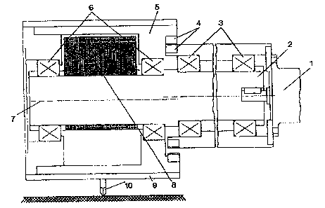
An assembly aec~rding to the pr~s~nt invention is shown in ngure 1 WhiCh
includes a sl~ve having a diameter of 300mm and a width of 300mm, equipped
wi~h 20 to ~0 milling tools. The sleeve may b~ driv8n at 3000rpm by m8ans of a
motoi rated at between 4kW and SkW. A reducti~n y~a~ arrar~ement causes
the sl~8ve to rotate at ~pproximat~ly 1 50rpm while oscillating at ~n amplitude of

- 2 -- 2~8318
5mm Th~ ntion allows other similar means of propulsion t~ be used. In a
furth~r ~mbodim~nt of ths invention (not illustrated~ the sleeve is rotat~bl0 a~appr~ximately 150rpm in opposition to th~ dir~ction of rotati~n of the eccentricdrive sha~t through frictional engagement ~etween the sle~ve and an adjacent
work area.
The scvere p~rcussi~ action by the rotatin~ tool at comparative~ small
applications of thrus~ is at~ributable to the hi~h r~ational speed of the
eccentrically m~unted tool mass. Count~rbalancin0 ~nsures smooth nJnning
conditions.
A compacting tool ac~or~ing to ~he inv~ntion may indud~ a cylindrical drum of
circular or triangular cross-section, the drurn havin~ planar suffaces in the la~ter
case.
A sleeve constituting a carrier for various tools may b~ provided for performingmillin~ or ripping op~rations in a single st~p, or in multipis steps. In yet a fur~her
emb~diment of the inventi~n (not illustrated) a rotata~le cutting disk may be
provid~d for working In ~xtremely hard rock formations whils ap,olying a thrust
~f s~veral hundred kilograrns only, compared to betw~en ZO ~nd 30 tonnes
required ~or ~ther pri~r machinery. The ass~mbii~s d4scrib~d above g~n~raliy
operat~ whil6 transferring or no vibration to the machine propelling the
rotat~ble tooi. Even quartzitic and oth~r hard rock may be mill~d in this mannerwi~hout ad~itional cooling.
The assernbly shown in fl~ure :2 and defined in clairn~ 4 an~ 5 has the ~naral
advantage that no s~parats propulsi~n for tools intendcd for use in millin0
ope~ations is rsquir~d. More particularly the cutting paths ~ ind~idual tools ar~
adjustabl0 for cutting greater ~epths into mason~, for e2wnple, witho~
ad~usting the eccentricity of an associated tool c~rrier.
Fi~ure ~ shows ons of several possibl~ embodiments o~ the ir~n~;~n, in wh~h
referenc~ n~lmeral 1 denotes a drivs motor which propels an ecc~ntric drive
sha~t ~ which is supported on two bearings 3. A r~duction ge~r arrangement 4,
which incl~Jdes an internally toothed ring ~ear m~shing with a pinion connectsd
to ~he motor 1 is provided for rotatin~ a tool c~rri~r 5 at a slower speed than th0
shaft 2. Th~ tool carrier 5 is support~d on th~ eccentric drive sh~ Z by means
. . . . , . . . ., ~ . . ..

- - 2 ~ .3 ;~ 8
of bearings 6, and is freely rotatabl~ about lhe shaft. Re~erence numeral 7
denotes the central axis of the eccentriG port~on of the driY~ shaft 2. Referen~e
numeral 8 d~not~s a s0~ of pra-sat count~ i0hts s~cur~d t~ th~ shaft ~. In the
presen~ embodiment o~ th~ inv~ntion th~ mass of ~ slidabiy locatabl~,
replaceabl~ sleeve 9, equipped with tools 10 and ~ in9 means, is
compansat~d with reference to the count~rweights 8 b~fors bsing mounted on
the carrier 5.
I:)ynamic balancing of the tooJs before installation on the eccentric drive is
d~sirabl~ to minimis~ any stresses acting on the bearings mentioned above
over ~xtended operating int~rvsls whila k~epin~ ener~y demands as low as
possibl~. .
In flg~lre 2 reference nurneral 11 denotes a milling tool for us0 in ripping or
planin~ operations. A bolt 12 or a similar fastening device is slide~ble in a slot
13 in the tool 11, and in its unsecured c~n~ition is displacsabl~ in relation to the
tool. When the ~olt 12 is position~d as shown in figure 2 the tool 11 produces
th~ small~st possible radial displacemen~ of th0 t~eth 15 during operati~n. On
the other h~nd when the bolt 12 is pos~ioned at the point i~nt~ d by reference
numeral 14 the r~dial amplitude of the oscillatin~ t~th 15 during operation is
maximised. Reference numeral 16 identrfi~s ths centrai axis of an eocentric
drivs shaR corresp~nding to the shaft 2 in figure 1, h~ving corr~sponding
counterwei~hts. A fix~cl ref~rance point for the purposes of adjustin~ the tool
11 may be located o~Jtside th~ spaG~ occupi~d by the tool itself, particularly if
the to~l is semi-circular or oth~rwiss shaped f~r the purposes ~ saving space.
The bolt 12 may ~llow r~dial and tangential displacement in relation to ths shaft
16. The assembly of figure 2 m~y b~ ad~pted for u~e in compact;ng operations
by providing means for propellin~ a tool ~orresponding to the tool 11 in a
gorward direction at optionally variable speeds.
Refer~nce numeral 16 serves to idant`fy an eccentric drive shaR corresponding
to that shown in fi~ure 1, while excludin~ the driv~ motor 1. The balt 1~ as
shown in figura 2, and at the position indioated by reference numeral 14, shows
the allowable range of adjustment f~r th~ cutting t~eth 15, bearing in mind thatths bolt 12 may be secured b~tween ei~er of thes~ extremes while located in
the slot 13. By option~liy adjusting ths tool 11 in a t~n~ential direction the
ds~r~e ~f ~scillation by th~ tools 15 may b~ further modi~ied. Thls may ser.~ to~chi~v~ a desir0d oscillation wh~n a machine equipped with the tools 15

_ 4_ 2~3~
opsratcs from a stationary location. By setting th~ bolt 12 in the pos~ion shownin flgure 2 ~hs cu~ting t~sth 15 d~scrib~ small circular paths 12a whe~eas the
t~eth descri~ lar~sr cuttins paths 14a when the bolt 12 i~ located in ths
~orresponding position 14. Thc amplitud~ of oscill~t;ons d~scrib~d by th~ axis
7 ~emains unaffected.

Representative Drawing
A single figure which represents the drawing illustrating the invention.
Administrative Status

2024-08-01:As part of the Next Generation Patents (NGP) transition, the Canadian Patents Database (CPD) now contains a more detailed Event History, which replicates the Event Log of our new back-office solution.

Please note that "Inactive:" events refers to events no longer in use in our new back-office solution.

For a clearer understanding of the status of the application/patent presented on this page, the site Disclaimer , as well as the definitions for Patent , Event History , Maintenance Fee  and Payment History  should be consulted.

Event History

Description Date
Inactive: IPC from MCD 2006-03-11
Time Limit for Reversal Expired 2005-10-13
Application Not Reinstated by Deadline 2005-10-13
Deemed Abandoned - Failure to Respond to Maintenance Fee Notice 2004-10-13
Inactive: Approved for allowance (AFA) 2004-10-12
Letter Sent 2004-09-22
Reinstatement Requirements Deemed Compliant for All Abandonment Reasons 2004-09-07
Reinstatement Request Received 2004-09-07
Amendment Received - Voluntary Amendment 2004-07-08
Reinstatement Request Received 2004-07-08
Reinstatement Requirements Deemed Compliant for All Abandonment Reasons 2004-07-08
Inactive: Abandoned - No reply to s.30(2) Rules requisition 2004-05-21
Inactive: Abandoned - No reply to s.29 Rules requisition 2004-05-21
Inactive: S.30(2) Rules - Examiner requisition 2003-11-21
Inactive: S.29 Rules - Examiner requisition 2003-11-21
Inactive: Entity size changed 2002-09-26
Amendment Received - Voluntary Amendment 2001-03-07
Inactive: Status info is complete as of Log entry date 2000-11-08
Letter Sent 2000-11-08
Inactive: Application prosecuted on TS as of Log entry date 2000-11-08
All Requirements for Examination Determined Compliant 2000-10-12
Request for Examination Requirements Determined Compliant 2000-10-12
Application Published (Open to Public Inspection) 1994-04-15

Abandonment History

Abandonment Date Reason Reinstatement Date
2004-10-13
2004-09-07
2004-07-08

Maintenance Fee

The last payment was received on 2003-10-08

Note : If the full payment has not been received on or before the date indicated, a further fee may be required which may be one of the following

  • the reinstatement fee;
  • the late payment fee; or
  • additional fee to reverse deemed expiry.

Please refer to the CIPO Patent Fees web page to see all current fee amounts.

Fee History

Fee Type Anniversary Year Due Date Paid Date
MF (application, 4th anniv.) - small 04 1997-10-14 1997-10-08
MF (application, 5th anniv.) - small 05 1998-10-13 1998-08-04
MF (application, 6th anniv.) - small 06 1999-10-13 1999-10-13
Request for examination - small 2000-10-12
MF (application, 7th anniv.) - small 07 2000-10-13 2000-10-12
MF (application, 8th anniv.) - small 08 2001-10-15 2001-10-11
MF (application, 9th anniv.) - standard 09 2002-10-14 2002-09-20
MF (application, 10th anniv.) - standard 10 2003-10-14 2003-10-08
Reinstatement 2004-07-08
Reinstatement 2004-09-07
Owners on Record

Note: Records showing the ownership history in alphabetical order.

Current Owners on Record
HANNELORE BECHEM
Past Owners on Record
KLAUS BECHEM
PHILIP BECHEM
ULRICH BECHEM
Past Owners that do not appear in the "Owners on Record" listing will appear in other documentation within the application.
Documents

To view selected files, please enter reCAPTCHA code :


To view images, click a link in the Document Description column. To download the documents, select one or more checkboxes in the first column and then click the "Download Selected in PDF format (Zip Archive)" or the "Download Selected as Single PDF" button.

List of published and non-published patent-specific documents on the CPD .

If you have any difficulty accessing content, you can call the Client Service Centre at 1-866-997-1936 or send them an e-mail at CIPO Client Service Centre.


Document
Description 
Date
(yyyy-mm-dd) 
Number of pages   Size of Image (KB) 
Representative drawing 1998-08-25 1 29
Representative drawing 2003-11-20 1 24
Cover Page 1994-05-28 1 22
Abstract 1994-05-28 1 8
Drawings 1994-05-28 2 43
Claims 1994-05-28 1 40
Description 1994-05-28 4 163
Description 2004-07-08 5 183
Claims 2004-07-08 1 28
Reminder - Request for Examination 2000-06-14 1 116
Acknowledgement of Request for Examination 2000-11-08 1 180
Courtesy - Abandonment Letter (R30(2)) 2004-08-02 1 166
Courtesy - Abandonment Letter (R29) 2004-08-02 1 166
Notice of Reinstatement 2004-09-22 1 171
Courtesy - Abandonment Letter (Maintenance Fee) 2004-12-08 1 176
Fees 2003-10-08 1 36
Fees 2001-10-11 1 35
Fees 2002-09-20 1 42
Fees 1997-10-08 1 59
Fees 1998-08-04 1 64
Fees 1999-10-13 1 52
Fees 2000-10-12 1 34
Correspondence 2004-08-05 1 21
Fees 1996-10-10 1 54
Fees 1995-10-13 1 51