Language selection

Search

Patent 2108371 Summary

Third-party information liability

Some of the information on this Web page has been provided by external sources. The Government of Canada is not responsible for the accuracy, reliability or currency of the information supplied by external sources. Users wishing to rely upon this information should consult directly with the source of the information. Content provided by external sources is not subject to official languages, privacy and accessibility requirements.

Claims and Abstract availability

Any discrepancies in the text and image of the Claims and Abstract are due to differing posting times. Text of the Claims and Abstract are posted:

  • At the time the application is open to public inspection;
  • At the time of issue of the patent (grant).
(12) Patent Application: (11) CA 2108371
(54) English Title: SEWAGE SYSTEM
(54) French Title: DISPOSITIF D'EVACUATION DES EAUX D'EGOUT
Status: Deemed Abandoned and Beyond the Period of Reinstatement - Pending Response to Notice of Disregarded Communication
Bibliographic Data
(51) International Patent Classification (IPC):
  • E03F 01/00 (2006.01)
  • E03B 07/00 (2006.01)
  • E03C 01/122 (2006.01)
(72) Inventors :
  • VAN BAAR, JACOBUS ELDERT MARIA
(73) Owners :
  • JOH. RANZIJN ENGINEERING B.V.
(71) Applicants :
  • JOH. RANZIJN ENGINEERING B.V.
(74) Agent: MARKS & CLERK
(74) Associate agent:
(45) Issued:
(86) PCT Filing Date: 1992-04-14
(87) Open to Public Inspection: 1992-10-29
Examination requested: 1999-03-29
Availability of licence: N/A
Dedicated to the Public: N/A
(25) Language of filing: English

Patent Cooperation Treaty (PCT): Yes
(86) PCT Filing Number: PCT/NL1992/000070
(87) International Publication Number: NL1992000070
(85) National Entry: 1993-10-13

(30) Application Priority Data:
Application No. Country/Territory Date
9100646 (Netherlands (Kingdom of the)) 1991-04-15

Abstracts

English Abstract

2108371 9218714 PCTABS00017
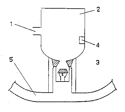
Sewage system comprised of a collector pipe (6) with one or more
house connections and to which collector pipe (6) an air
compressor and/or a vacuum pump is connected, wherein a house connection
is comprised of a collecting gully (2) with a connection for the
house sewer pipe (1), and which gully (2) at its bottom side is
provided with a valve (3), which may be operated under the control
of a level switch (4) arranged in the gully, while the valve (3)
at the discharge side is connected to the collected pipe (6),
which at that place is provided with a bend (5) situated in a
vertical plane, to the middle part of which the valve (3) is connected
and from which both the sideways running bend parts run upwards
up to a height below the valve (3).


Claims

Note: Claims are shown in the official language in which they were submitted.


NEW CLAIMS
1. Sewage system comprising a collector pipe (5, 6)
with a plurality of house connections and an air compressor
(7) and/or a vacuum pump connected to said collector pipe,
wherein a house connection comprises a collecting gully (2)
with a connection for the house sewer pipe (1), wherein said
gully (2) at its bottom side is provided with a valve (3)
which may be operated under the control of a level switch
arranged in said gully, while the valve at the discharge side
is connected to the collector pipe (5, 6), characterized in
that the sewage system is arranged in such a manner that upon
operation of the valve (3) of one collecting gully (2) the
valves (3) of the other gullies (2) of the sewage system are
operated and the compressor (7) and/or the vacuum pump is put
into operation in order to push and/or suck away the sewage
water of all collecting gullies connected to the collector
pipe (5, 6).
2. Sewage system according to claim 1, characterized
in that the collector pipe (5, 6) at the location of a house
connection is provided with a bend (5), to the middle part of
which the valve (3) is connected.
3. Sewage system according to claim 2, characterized
in that the bend (5) has a capacity which is sufficient to
receive the maximum content of sewage water in the collecting
gully (2).

Description

Note: Descriptions are shown in the official language in which they were submitted.


r ~ tJ 7
sewage system
r ~
The invention relates to a sewage system of the type
according to the preamble of claim 1.
Such a sewage system is disclosed in EP-A-O 239 892.
In this known sewage system the valve of each collecting gully
is operated at a predetermined maximum water level in the
collecting gully. The compressor and/or vacuum pump provides
for a transport through the collector pipe of the sewage water
emptied from the gully into the collector pipe.
The drawback of the mere application of a compressor
and/or a vacuum pump lies in the circumstance, that the
consumption of energy is high, as in substance air is thereby
circulated or sucked through the collector pipe, without this
helping along in an efficient manner the flow of the sewage
water in the pipe.
The invention aims to obviate this drawback of the
known sewage~system.
To this end the sewage system of the invention is
characterized by the features of the characterizing part of
claim 1.
In this manner the sewage water of all connecting
gullies is transported through the collector pipe in one
operation of the compressor and/or the vacuum pump which
results in a more efficient operation of the sewage system.
Further, it is not re~uired with the sewage system
according to the invention that the compressor and/or the
vacuum pump are continuously in operation, and these can be
put into operation solely and directly after the discharge of
the sewage water in the gully into the collector pipe, by
which an important saving of energy is obtained.
A favourable embodiment of the sewage system of the
invention is further characterized by the features of claim 2.
In a favourable way the bend according to a further
characteristic of the invented sewage system further has a
capacity which is sufficient to take in the maximum content of
sewage water in the collecting gully.
Through the application of the bends near the house
connections it is achieved, that after the discharge o~ the
sewage water out of the collecting gullies, the collector pipe
SUESSTITUTE SHEET
.. , ., ................ ... . ~ `
, - .. ` . : '
... ~ .
.. `
.,
:: .
-

~, n~o,.~.7l
r
near the bends is c-~mpletel~,,silut off~by the sewase water, by
which at the pushing away or sucking in of the sewage water in
the collector pipe the energy losses through air leakages in
the collector pipe above the sewage water are substantially
S diminished.
SUBSTITUTE SJIEEl
. . . . .
.

3 ~ ? 7 1
i,.......................................... .
T.he invention will now be described, by way of example, with
reference to the acoonpanying d~awings.
~igure 1 shows a representation of a collecting gully with a
connection to a collec.or pipe and a oonnec~ion to a house se~er
pipe.
Figure 2 shcws a scnematic representation of the sewage svstem.
As is shown in figure 1 the house sewe~- pipe 1 is connecte~ to
the collect m g gully 2, a~d wnich at its bottom side is prcvided
wi h a va_ve 3, which may e operated unce- ~he conr-ol of 2
level switch 4 arranged in the gully 2, such, that at the
reaching of a determ~ned maximum content of sewage wate_ in the
gully, the valve 3 is opened through an electrical means and the
content of the gully may flow away downwar~s to ~e taken in in
r-qe b~!~d 5, which fo = pæ- of ~.e collector pipe.
As is s.~own m figure 2, the collector pipe 5, 6 below eac~
collecting gully 2 is provided with a bend 5 which can take m
.the max~mum cont_nt of a collecting gully.
At the end opposite frcm the direction of the flcw of the sewage
water the collector pipe 6 is connected to the compress~ 7, by
means of which after the opening of the valve 8 de content of the
bends 5 may be pushed away to the discharge side of the collec~or
pipe.
Ihe connecticns of the gullies 2 to the collector pipe 5, 6 and
the circuit of the level switches of the ~.Lined gullies is such
SUBSTITUTF SHEE~'
. ,
,

~...W O 92/18714 2 l ~ 7 t P ~ /NL9t/00070-
.. .
- 4 -
that, when in a gully the level switch at the reaching of the
maximum height of the sewage water within the gully is operatæ,
by that all the valves of the oombined gullies 2 are opened, and
the cantents of the gullies are t~ken in in the below situated
bends 5 of the collector pipe 5, 6.
Next the valves 3 of the gullies 2 are closed, ;he ccTpressor 7
is put into CQeration and the valve 8 is cpened, and after which
the sewage watOE is pushed away out of the bends 5.
. . . ;; ., ~ ,
- ..
~ , :
.
.

Representative Drawing
A single figure which represents the drawing illustrating the invention.
Administrative Status

2024-08-01:As part of the Next Generation Patents (NGP) transition, the Canadian Patents Database (CPD) now contains a more detailed Event History, which replicates the Event Log of our new back-office solution.

Please note that "Inactive:" events refers to events no longer in use in our new back-office solution.

For a clearer understanding of the status of the application/patent presented on this page, the site Disclaimer , as well as the definitions for Patent , Event History , Maintenance Fee  and Payment History  should be consulted.

Event History

Description Date
Application Not Reinstated by Deadline 2002-04-15
Time Limit for Reversal Expired 2002-04-15
Deemed Abandoned - Failure to Respond to Maintenance Fee Notice 2001-04-17
Inactive: Entity size changed 2000-05-23
Inactive: Office letter 2000-05-09
Inactive: Status info is complete as of Log entry date 1999-04-12
Inactive: Application prosecuted on TS as of Log entry date 1999-04-12
Inactive: RFE acknowledged - Prior art enquiry 1999-04-12
Request for Examination Requirements Determined Compliant 1999-03-29
All Requirements for Examination Determined Compliant 1999-03-29
Inactive: Adhoc Request Documented 1997-04-14
Deemed Abandoned - Failure to Respond to Maintenance Fee Notice 1997-04-14
Application Published (Open to Public Inspection) 1992-10-29

Abandonment History

Abandonment Date Reason Reinstatement Date
2001-04-17
1997-04-14

Maintenance Fee

The last payment was received on 2000-04-14

Note : If the full payment has not been received on or before the date indicated, a further fee may be required which may be one of the following

  • the reinstatement fee;
  • the late payment fee; or
  • additional fee to reverse deemed expiry.

Patent fees are adjusted on the 1st of January every year. The amounts above are the current amounts if received by December 31 of the current year.
Please refer to the CIPO Patent Fees web page to see all current fee amounts.

Fee History

Fee Type Anniversary Year Due Date Paid Date
MF (application, 6th anniv.) - standard 06 1998-04-14 1998-04-09
MF (application, 7th anniv.) - standard 07 1999-04-14 1999-03-29
Request for examination - standard 1999-03-29
MF (application, 8th anniv.) - small 08 2000-04-14 2000-04-14
Owners on Record

Note: Records showing the ownership history in alphabetical order.

Current Owners on Record
JOH. RANZIJN ENGINEERING B.V.
Past Owners on Record
JACOBUS ELDERT MARIA VAN BAAR
Past Owners that do not appear in the "Owners on Record" listing will appear in other documentation within the application.
Documents

To view selected files, please enter reCAPTCHA code :


To view images, click a link in the Document Description column (Temporarily unavailable). To download the documents, select one or more checkboxes in the first column and then click the "Download Selected in PDF format (Zip Archive)" or the "Download Selected as Single PDF" button.

List of published and non-published patent-specific documents on the CPD .

If you have any difficulty accessing content, you can call the Client Service Centre at 1-866-997-1936 or send them an e-mail at CIPO Client Service Centre.

({010=All Documents, 020=As Filed, 030=As Open to Public Inspection, 040=At Issuance, 050=Examination, 060=Incoming Correspondence, 070=Miscellaneous, 080=Outgoing Correspondence, 090=Payment})


Document
Description 
Date
(yyyy-mm-dd) 
Number of pages   Size of Image (KB) 
Drawings 1994-06-30 1 11
Claims 1994-06-30 1 34
Abstract 1995-08-16 1 60
Description 1994-06-30 4 100
Description 1999-04-29 4 115
Claims 1999-04-29 1 36
Representative drawing 1998-11-24 1 6
Reminder - Request for Examination 1998-12-14 1 116
Acknowledgement of Request for Examination 1999-04-11 1 173
Courtesy - Abandonment Letter (Maintenance Fee) 2001-05-14 1 182
PCT 1993-10-12 30 1,015
Correspondence 2000-05-17 2 93
Correspondence 2000-05-09 2 10
Fees 2000-04-13 1 50
Fees 1998-04-08 1 56
Fees 1999-03-28 1 55
Fees 1997-04-06 1 55
Fees 1996-04-03 1 41
Fees 1994-09-13 1 40
Fees 1993-10-12 1 59