Language selection

Search

Patent 2108403 Summary

Third-party information liability

Some of the information on this Web page has been provided by external sources. The Government of Canada is not responsible for the accuracy, reliability or currency of the information supplied by external sources. Users wishing to rely upon this information should consult directly with the source of the information. Content provided by external sources is not subject to official languages, privacy and accessibility requirements.

Claims and Abstract availability

Any discrepancies in the text and image of the Claims and Abstract are due to differing posting times. Text of the Claims and Abstract are posted:

  • At the time the application is open to public inspection;
  • At the time of issue of the patent (grant).
(12) Patent: (11) CA 2108403
(54) English Title: ELECTRICAL DISTRIBUTION EQUIPMENT WITH TORQUE ESTIMATING CAPABILITY
(54) French Title: DISPOSITIF POUR CIRCUIT D'ALIMENTATION ELECTRIQUE AVEC CAPACITE D'EVALUATION DE COUPLE
Status: Expired
Bibliographic Data
(51) International Patent Classification (IPC):
  • H02H 7/09 (2006.01)
  • G01R 31/34 (2006.01)
  • H02H 7/08 (2006.01)
(72) Inventors :
  • KLIMAN, GERALD BURT (United States of America)
  • SRINIVASAN, KAMAKSHI (United States of America)
  • DEDONCKER, RIK WIVINA ANNA ADELSON (United States of America)
  • RITSCHER, DAVID ERIC (United States of America)
(73) Owners :
  • GENERAL ELECTRIC COMPANY (United States of America)
(71) Applicants :
  • GENERAL ELECTRIC COMPANY (United States of America)
(74) Agent: CRAIG WILSON AND COMPANY
(74) Associate agent:
(45) Issued: 2004-12-14
(22) Filed Date: 1993-10-14
(41) Open to Public Inspection: 1995-04-15
Examination requested: 2000-09-28
Availability of licence: N/A
(25) Language of filing: English

Patent Cooperation Treaty (PCT): No

(30) Application Priority Data: None

Abstracts

English Abstract

A circuit breaker for protecting a motor-driven system from overcurrents and undervoltages includes both current and voltage sensors and derives a precise estimate of electromagnetic torque output from sensed currents and voltages. A contactor similarly includes torque estimating capability.


French Abstract

Un disjoncteur de protection d'un système motorisé contre les surintensités et les sous-tensions comprend des capteurs de courant et de tension et dérive une estimation précise du couple électromagnétique résultant à partir des tensions et intensités mesurées. Un contacteur comprend de même une capacité d'évaluation de couple.

Claims

Note: Claims are shown in the official language in which they were submitted.


-11-
WHAT IS CLAIMED IS:
1. A circuit breaker for use in a system
driven by a motor, comprising:
current sensing means for measuring current
in each respective phase of the motor;
voltage sensing means for measuring voltage
across each respective phase of the motor;
actuating means for controlling contacts
operatively connected within each respective phase of
the motor, said actuating means operating said
contacts in response to indication of one of an
overcurrent condition by the current sensing means and
an undervoltage condition by the voltage sensing
means, respectively; and
computer means for receiving the measured
current in each respective phase and the measured
voltage across each respective phase from said current
sensing means and said voltage sensing means,
respectively, and for controlling said actuating means
in response thereto, said computer means further
comprising torque estimating means for estimating
torque output of the motor from the measured current
in each respective phase and the measured voltage
across each respective phase.
2. The circuit breaker of claim 1 in a
three-phase system, said torque estimating means
transforming the measured current in each respective


-12-
phase and the measured voltage across each respective
phase into a two-phase stator reference frame and
deriving the estimated torque output T e as follows:
Image
where p represents a stator pole pair number for said
motor; and .lambda.sd. .lambda.sq. i sd, and i sq are transformed two-
phase components of stator fluxes of said motor and
the measured current in each respective phase,
respectively.
3. The circuit breaker of claim 1 wherein
said current sensing means comprises current sensing
transformers.
4. The circuit breaker of claim 1 wherein
said voltage sensing means comprises potential
transformers.
5. The circuit breaker of claim 1, further
comprising a casing for enclosure thereof.
6. The circuit breaker of claim 1 wherein
said current sensing means and said voltage sensing
means are contained within a sensing module separate
from said actuating means, said contacts, and said
computer means.
7. The circuit breaker of claim 1, further
comprising means for coupling said computer means to a
communication means for remotely controlling said


-13-
actuating means through said computer means.
8. The circuit breaker of claim 1 wherein
said voltage and current sensing means, said actuating
means, and said torque estimating means are each
respectively packaged within a separate module.
9. A contactor for use in a system driven by
a motor, comprising:
current sensing means for measuring current
in each respective phase of the motor;
voltage sensing means for measuring voltage
across each respective phase of the motor;
actuating means for controlling contacts
operatively connected within each respective phase of
the motor, said actuating means operating said
contacts in response to a control signal; and
computer means for receiving the measured
current in each respective phase and the measured
voltage across each respective phase from said current
sensing means and said voltage sensing means,
respectively, and for controlling said actuating means
in response thereto, said computer means further
comprising torque estimating means for estimating
torque output of the motor from the measured current
in each respective phase and the measured voltage
across each respective phase.
10. The contactor of claim 9 in a three-
phase system, said torque estimating means


-14-
transforming the measured current in each respective
phase and the measured voltage across each respective
phase into a two-phase stator reference frame and
deriving the estimated torque output T e as follows:
Image
where p represent: a stator pole pair number for said
motor; and .lambda.sd, .lambda.sq. i sd, and i sq are transformed two-
phase components of stator fluxes of said motor and
the measured current in each respective phase,
respectively.
11. The contactor of claim 9 wherein said
current sensing means comprises current sensing
transformers.
12. The contactor of claim 9 wherein said
voltage sensing means comprises potential
transformers.
13. The contactor of claim 9, further
comprising a casing for enclosure thereof.
14. The contactor of claim 9 wherein said
current sensing means and said voltage sensing means
are contained within a sensing module separate from
said actuating means, said contacts, and said computer
means.
15. The contactor of claim 9, further
comprising means for coupling said computer means to a
communication means for remotely controlling said


-15-
actuating means through said computer means.
16. The contactor of claim 9 wherein said
voltage and current sensing means, said actuating
means, and said torque estimating means are each
respectively packaged within a separate module.
17. An electrical distribution system in a
control center for a motor, comprising:
current sensing means for measuring current
in each respective phase of the motor;
voltage sensing means for measuring voltage
across each respective phase of the motor;
actuating means for controlling contacts
operatively connected within each respective phase of
the motor, said actuating means operating said
contacts in response to indication of one of an
overcurrent condition by the current sensing means and
an undervoltage condition by the voltage sensing
means, respectively:
computer means for controlling said
actuating means in response thereto, said computer
means further comprising torque estimating means for
receiving the measured current in each respective
phase and the measured voltage across each respective
phase from said current sensing means and said voltage
sensing means, respectively, and for estimating torque
output of the motor therefrom; and
means for coupling said torque estimating

-16-

means to a communication means for remotely
controlling a motor in response to the estimated
torque output from said torque estimating means.
18. The electrical distribution system of
claim 17 comprising a three-phase system, said torque
estimating means transforming the measured current in
each respective phase and the measured voltage across
each respective phase into a two-phase stator
reference frame and deriving the estimated torque
output T e as follows:
Image
where p represents a stator pole pair number for said
motor, and .lambda.sd. .lambda.sq. i sd, and i sq are transformed two-
phase components of stator fluxes of said motor and
the measured currents, respectively.
19. The electrical distribution system of
claim 17 wherein said current sensing means comprises
current sensing transformers.
20. The electrical distribution system of
claim 17 wherein said voltage sensing means comprises
potential transformers.
21. The electrical distribution system of
claim 17 wherein said current sensing means and said
voltage sensing means are contained within a sensing
module separate from said torque estimating means.

Description

Note: Descriptions are shown in the official language in which they were submitted.


RD0021535
~~~~~~J
_ 1 _
Field of the Invention
The present invention relates generally to
electrical distribution equipment. More particularly,
the present invention relates to a circuit breaker or
a contactor including torque estimating apparatus for
deriving torque measurements from circuit breaker or
contactor sensors employed therein.
Background of the Invention
In a motor system, it is often necessary to
monitor the torque produced by the motor, particularly
if the motor is being used to drive a complex load,
such as, for example, a pump or a valve.
Electromechanical torque transducer systems are
sometimes employed, but are limited due to physical
constraints, high costs, and lack.af reliability and
robustness. A recent alternative for monitoring
torque relies on the current sensed by a single
current transformer in one of three phases supplying
the drive motor. In particular, the current is
assumed to represent a scaled version of the actual
torque produced by the motor.
Unfortunately, however, as derived from the
steady-state equivalent circuit of an induction motor,
the relationship between current and output torque (or
shaft torque) is not fixed, but varies as both power
factor and efficiency change at different loads and
speeds, as shown in Figure 1. Other factors which


RD0021535
2~.~~~~
- 2 -
affect the relationship between current and shaft
torque include rotor electrical and mechanical time
constants and saturation. Therefore, using current to
deduce the state of the load and the nature of faults
results in significant errors.
Another method for monitoring torque output
in an induction motor involves a model-based approach
wherein knowledge of motor parameters (e.g., rotor and
stator resistances, leakage inductances and
magnetizing inductance) and motor speed is required in
addition to motor currents and voltages.
Unfortunately, however, motor parameters must be
given, measured or estimated; and estimation under
transient conditions is difficult and may involve
complex computations.
Accordingly, it is desirable to provide
means for precisely estimating torque in an induction
motor using both current and voltage information,
which information can be provided from circuit breaker
sensors that function to protect the motor from
overcurrents and undervoltages. Similarly, such
information can be provided from contactor sensors or
similar devices in a motor control center.
Furthermore, it is desirable that such torque
measurements be made without requiring measurements of
motor parameters or speed.
SummarSr of the Invention
A circuit breaker for protecting a motor-
driven system from overcurrents and undervoltages


RD0021535
- 3 -
includes current and voltage sensors and torque
estimating means for generating torque measurements
from sensed currents and voltages. The torque
estimating means is implemented in software on a
computer control chip for the circuit breaker.
Advantageously, therefore, the state of the load on
the motor shaft is precisely determined without
requiring knowledge of speed or parameters of the
motor.
In similar fashion, a contactor includes
current and voltage sensors and torque estimating
means for generating torque measurements from sensed
currents and voltages.
20
Grief Descrj~tion of the Drawings
The features and advantages of the present
invention will become apparent from the following
detailed description of the invention when read with
the accompanying drawing in which:
Figure 1 is a graphical representation of
shaft torque as a function of line current for a
typical motor;
Figure 2 is a schematic diagram
illustrating a circuit breaker or contactor including
torque estimating means according to the present
invention;
Figure 3 graphically represents: (a)
measured torque according to conventional mechanical


RD0021535
~~~~~~J
- 4 -
methods; (b) a torque estimate according to the
present invention; and (c) RMS motor current; and
Figure 4 schematically illustrates an
alternative embodiment of the circuit breaker or
contactor of Figure 2.
petailed Desc ~gtion of the
Invention
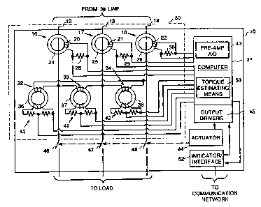
Figure 2 schematically illustrates a
circuit breaker or contactor for a motor-driven system
according to the present invention including means for
providing precise measurements of the output torque of
the motor. The circuit breaker or contactor of Figure
2 is illustrated as being contained within a case 10.
Input lines 12-14 are coupled to a three-phase ac
power source (not shown). Currents in lines 12-14 are
sensed by current sensors 16-18, respectively, which
are illustrated in Figure 2 as comprising current
transformers. However, other suitable current sensors
may be used, such as, for example, Hall-effect current
sensors or flux-null systems. Each current
transformer comprises a coil 20-22 wound about a
respective transformer core 24-26. A resistor 28-30
is coupled across each coil 20-22, respectively, such
that the voltage across the respective resistor 28-30
is proportional to the current through the
corresponding input line 12-14, respectively. The
output of each current transformer is provided to a
computer system 31 for controlling the circuit
breaker.


RD0021535
~~~~'~~J
- 5 -
The circuit breaker or contactor of Figure
1 further includes voltage sensors 32-34 for sensing
the voltage across each motor phase. The voltage
sensors are illustrated as comprising potential
transformers 36-38 and resistive voltage dividers 40-
42. However, other suitable voltage sensors may be
used such as capacitive or resistive voltage dividers.
The voltage at the output of each divider 40-42 is
provided to computer system 31 (via analog-to-digital
A/D converters 43) and is proportional to the
respective motor phase voltage.
A contact actuator 44 is controlled by
computer system 31 via output driver circuitry 45 for
opening or closing contacts 46-48 in response to wn
overcurrent or undervoltage (i.e., for a circuit
breaker) or another predetermined current signal
(i.e., for a contactor), as sensed by current sensors
16-18, in well-known fashion. Alternatively, actuator
49 may be controlled via computer system 31 by a
remote command according to methods well-known in the
art.
Computer system 31 further comprises torque
estimating means 50 for supplying torque estimates to
an indicator/interface 52 which supplies the torque
measurements to a communication network, as
illustrated, or provides a read-out of the torque
measurements either locally or remotely, as desired.
In accordance with the present invention,
torque estimating means 50 generates torque estimates


RD0021535
~1Q~~~3
- 6 -
in response to the measured currents and voltages from
sensors 16-18 and 32-34, respectively, using the
following expression for electromagnetic torque Te in
an electrical machine:
_ dL (8)
Te - 2 1T d8 1 (1)
where L(8) represents an inductance matrix for the
motor, and iT represents the transpose of the current
vector i where:
i = [islr is2r is3r irlr ir2. ir3l. and
isl
is2
iT = is3
irl
ir2
ir3
with isi representing the three-phase stator currents
and ir3 representing the three-phase rotor currents
(subscript i = 1, 2, 3). Similarly, the three-phase
stator and rotor voltages are represented by the
vector:
V ° ~VSli Vs2r Vs3i Vrlr Vr2r Vr3~
The voltages may then be integrated to provide the
flux linkages:
~~slr ~s2~ ~s3r ~rlr ~r2~ ~r3)~


RD0021535
Transforming all variables in equation (1)
to a stator reference frame and from a three-phase to
two-phase coordinate system in well-known manner, the
electromagnetic torque Te may be represented in terms
of the stator flux linkages and the stator currents
as:
Te = 2 P I~I,sdigq - isd~sql (2)
where p represents the pole pair number; and ~,gd, ~.sq,
isd, and isq are the two-phase components of the
stator fluxes and the stator currents, respectively.
The transformed two-phase components of the stator
currents and stator voltages are represented in terms
of the three-phase components as follows:
isd = isl
'f3 ~3
isq -= 3 (ls2 ' is3) 3 (isl + 2is2)
vsd = vsl
vsq = 3 (vs2 - vs3) = 3 (vsl + 2vs2)
The transformed components of the stator currents and
stator fluxes may also be related as follows:
dt C ~sd, ~ vsd ~ _ ~ lsd ~ ~ rs 0
~,sq sq sq 0 rs . (3)


RD0021535
~~~~~~J
_ g _
where r9 represents the stator resistance. The stator
voltages and currents are measured by the voltage and
current sensors, as described hereinabove; and the
stator resistance rs is easily measured. (Use of the
stator resistance measurement improves the precision
of the torque estimations.) Torque is thus determined
precisely from these measurements by torque estimating
means 50 using equations (2) and (3) .
For comparison, Figure 3a graphically
illustrates torque measured during operation of a
three-phase motor using an electromechanical torque
transducer, and Figure 3b illustrates torque estimated
according to the present invention. Figure 3c
illustrates the RMS motor current. By comparing~the
graphs of Figures 3a and 3b, it is apparent that the
torque estimating means of the present invention
provides precise torque estimations. In fact, the
torque estimating means provides an even better
measure of torque than the torque transducer at zero
torque. Moreover, the graph of Figure 3c, as compared
with the graphs of Figures 3a and 3b, further
exemplifies how current is not a scaled version of the
actual torque produced by the motor.
According to an alternative embodiment,
the voltage and current sensors are contained within a
module 80 separate from computer system 31 and the
circuit breaker or contactor, as indicated by the
dashed lines in Figure 2. In this way, even higher
precision voltage and current measurements, and hence


RD0021535
21~~~~~
_ g
torque estimates, are derived by avoiding the use of
miniaturized components.
In still another alternative embodiment, as
illustrated schematically in Figure 4, there are three
modules for containing: (1) the current and voltage
sensors (shown as current transformers CT's and
potential transformers PT's, respectively); (2) the
circuit breaker or contactor 10' with a modified
computer system 31' (i.e., without the torque
estimating means); and (3) torque estimating means
50'. For this embodiment, the torque estimating means
includes its own electronics, i.e., A/D converters and
controls, separate from those of circuit breaker or
contactor 10'.
Advantageously, a circuit breaker according
to the present invention provides overcurrent and
undervoltage protection and precise torque estimating
capability within a single package. Similarly, a
contactor according to the present invention includes
torque estimating capability. Hence, the state of a
motor-driven load can be accurately and reliably
determined as well as the nature of faults in the
motor or load.
While the preferred embodiments of the
present invention have been shown and described
herein, it will be obvious that such embodiments are
provided by way of example only. Numerous variations,
changes and substitutions will occur to those of skill
in the art without departing from the invention


RD0021535
.. ~~~~~~J
- 10 -
herein. Accordingly, it is intended that the
invention be limited only by the spirit and scope of
the appended claims.

Representative Drawing
A single figure which represents the drawing illustrating the invention.
Administrative Status

For a clearer understanding of the status of the application/patent presented on this page, the site Disclaimer , as well as the definitions for Patent , Administrative Status , Maintenance Fee  and Payment History  should be consulted.

Administrative Status

Title Date
Forecasted Issue Date 2004-12-14
(22) Filed 1993-10-14
(41) Open to Public Inspection 1995-04-15
Examination Requested 2000-09-28
(45) Issued 2004-12-14
Expired 2013-10-15

Abandonment History

There is no abandonment history.

Payment History

Fee Type Anniversary Year Due Date Amount Paid Paid Date
Application Fee $0.00 1993-10-14
Registration of a document - section 124 $0.00 1994-05-10
Maintenance Fee - Application - New Act 2 1995-10-16 $100.00 1995-09-20
Maintenance Fee - Application - New Act 3 1996-10-14 $100.00 1996-09-19
Maintenance Fee - Application - New Act 4 1997-10-14 $100.00 1997-09-18
Maintenance Fee - Application - New Act 5 1998-10-14 $150.00 1998-09-16
Maintenance Fee - Application - New Act 6 1999-10-14 $150.00 1999-09-24
Request for Examination $400.00 2000-09-28
Maintenance Fee - Application - New Act 7 2000-10-16 $150.00 2000-09-28
Maintenance Fee - Application - New Act 8 2001-10-15 $150.00 2001-09-27
Maintenance Fee - Application - New Act 9 2002-10-14 $150.00 2002-09-26
Maintenance Fee - Application - New Act 10 2003-10-14 $200.00 2003-09-25
Final Fee $300.00 2004-09-23
Maintenance Fee - Application - New Act 11 2004-10-14 $250.00 2004-09-23
Maintenance Fee - Patent - New Act 12 2005-10-14 $250.00 2005-09-21
Maintenance Fee - Patent - New Act 13 2006-10-16 $250.00 2006-09-18
Maintenance Fee - Patent - New Act 14 2007-10-15 $250.00 2007-09-17
Maintenance Fee - Patent - New Act 15 2008-10-14 $450.00 2008-09-17
Maintenance Fee - Patent - New Act 16 2009-10-14 $450.00 2009-09-18
Maintenance Fee - Patent - New Act 17 2010-10-14 $450.00 2010-09-17
Maintenance Fee - Patent - New Act 18 2011-10-14 $450.00 2011-09-19
Maintenance Fee - Patent - New Act 19 2012-10-15 $450.00 2012-09-17
Owners on Record

Note: Records showing the ownership history in alphabetical order.

Current Owners on Record
GENERAL ELECTRIC COMPANY
Past Owners on Record
DEDONCKER, RIK WIVINA ANNA ADELSON
KLIMAN, GERALD BURT
RITSCHER, DAVID ERIC
SRINIVASAN, KAMAKSHI
Past Owners that do not appear in the "Owners on Record" listing will appear in other documentation within the application.
Documents

To view selected files, please enter reCAPTCHA code :


To view images, click a link in the Document Description column. To download the documents, select one or more checkboxes in the first column and then click the "Download Selected in PDF format (Zip Archive)" or the "Download Selected as Single PDF" button.

List of published and non-published patent-specific documents on the CPD .

If you have any difficulty accessing content, you can call the Client Service Centre at 1-866-997-1936 or send them an e-mail at CIPO Client Service Centre.


Document
Description 
Date
(yyyy-mm-dd) 
Number of pages   Size of Image (KB) 
Cover Page 1995-06-06 1 74
Claims 1995-06-06 7 471
Representative Drawing 1998-07-29 1 25
Claims 2000-09-28 6 195
Representative Drawing 2004-03-17 1 16
Abstract 1995-06-06 1 11
Description 1995-06-06 10 268
Drawings 1995-06-06 4 67
Cover Page 2004-11-10 1 42
Assignment 1993-10-14 8 291
Prosecution-Amendment 2000-09-28 11 329
Correspondence 2004-09-23 1 27
Fees 1996-09-19 1 53
Fees 1995-09-20 1 50