Language selection

Search

Patent 2108510 Summary

Third-party information liability

Some of the information on this Web page has been provided by external sources. The Government of Canada is not responsible for the accuracy, reliability or currency of the information supplied by external sources. Users wishing to rely upon this information should consult directly with the source of the information. Content provided by external sources is not subject to official languages, privacy and accessibility requirements.

Claims and Abstract availability

Any discrepancies in the text and image of the Claims and Abstract are due to differing posting times. Text of the Claims and Abstract are posted:

  • At the time the application is open to public inspection;
  • At the time of issue of the patent (grant).
(12) Patent Application: (11) CA 2108510
(54) English Title: KITCHEN VENTILATOR
(54) French Title: VENTILATEUR DE CUISINE
Status: Deemed Abandoned and Beyond the Period of Reinstatement - Pending Response to Notice of Disregarded Communication
Bibliographic Data
(51) International Patent Classification (IPC):
  • F24F 07/06 (2006.01)
  • F04D 29/66 (2006.01)
  • F24C 15/20 (2006.01)
(72) Inventors :
  • CASTWALL, LENNART WILHELM (Sweden)
(73) Owners :
  • AKTIEBOLAGET ELECTROLUX
(71) Applicants :
  • AKTIEBOLAGET ELECTROLUX (Sweden)
(74) Agent: SMART & BIGGAR LP
(74) Associate agent:
(45) Issued:
(22) Filed Date: 1993-10-15
(41) Open to Public Inspection: 1994-05-04
Availability of licence: N/A
Dedicated to the Public: N/A
(25) Language of filing: English

Patent Cooperation Treaty (PCT): No

(30) Application Priority Data:
Application No. Country/Territory Date
9203248-1 (Sweden) 1992-11-03

Abstracts

English Abstract


Abstract
A kitchen ventilator comprises a housing (10) having a motor
powered fan (20), an inlet (11), an inlet passage (25) between
the inlet and the fan, an outlet (17), and an outlet passage (23)
between the fan and the outlet, said passages being separated by
a generally vertical partition wall (22). The inlet passage is
partially formed by a baffle wall (26) provided between the inlet
and the fan, and a removable front wall (16) provided with a
sound absorbing material, and the outlet passage (23) has a
narrowing portion (33) which is provided on both sides with sound
absorbing material (18, 19).
For reducing the noice level, the ventilator is provided with
means for active silencing, comprising an acoustic sensor (28)
for sensing the noice of the fan, a loudspeaker (30) for emitting
a sound silencing the fan noice in reverse phase therewith, and
an electronic control unit (29) connected to said sensor and said
loudspeaker and adapted to control the loudspeaker in response
to information received from said sensor.
(Figure 1)


Claims

Note: Claims are shown in the official language in which they were submitted.

Claims
1. Kitchen ventilator comprising a housing (10), a motor powered
fan (20) having a horizontal axis arranged in the bottom portion
of the housing, an inlet (11), an inlet passage (25) extending
between the inlet and the fan, an outlet (17), and an outlet
passage (23) extending between the fan and the outlet, said
passages being separated by a generally vertical partition wall
(22), characterized in that the inlet passage is formed partially
by a baffle wall (26) provided between the inlet (11) and the fan
(20) and a removable front wall (16) provided with a sound
absorbing material, said outlet passage (23) having a narrowing
portion (33) which is provided on both sides with sound absorbing
material (18, 19).
2. Kitchen ventilator according to claim 1, characterized in
that the outlet passage (23) is provided with a bracket (32) for
a removable odour filter (24).
3. Kitchen ventilator according to claim 1 or 2, characterized
by means for active silencing comprising an acoustic sensor (28)
for sensing the noice of the fan, a loudspeaker (30) for emitting
a sound silencing the fan noice in reverse phase therewith, and
an electronic control unit (29) connected to said sensor and said
loudspeaker and adapted to control the loudspeaker in response
to information received from said sensor.
4. Kitchen ventilator according to claim 3, characterized by a
first acoustic sensor (28) for sensing the fan noice in the
vicinity of the fan (20), and a second acoustic sensor (31) for
sensing the fan noice at the inlet (11), both sensors being
coannected to the control unit (29) whereby the sound emitted by
the loudspeaker is corrected in response to information received
from said second sensor.

Description

Note: Descriptions are shown in the official language in which they were submitted.


Kitchen ventilator 210 8 .~1~ c~Be w 5~8
The present invention relates to a kitchen ventilator
comprising a housing, a motor powered fan having a horizontal
axis arranged in the bottom portion of the housing, an inlet, an
inlet passage between the inlet and the fan, an outlet, and an
outlet passage between the fan and the outlet, said passages
being separated by a generally vertical partition wall.
In order to efficiently collect fumes produced in connection
with cooking a relatively heavy air flow is required and in order
to obtain this a large capacity fan is necessary. The drawback
of such a fan is that it produces a relatively heavy, disturbing
noise.
The object of the invention is to reduce this problem by
providing a ventilator in which the noice level has been
minimized. This has been obtained by means of a ventilator of the
kind mentioned in the introduction, which according to the
invention is characterized in that the inlet passage is formed
partially by a baffle wall provided between the inlet and the
fan, and a removable front wall provided with a sound absorbing
material, said outlet passage having a narrowing portion which
is provided on both sides with sound absorbing material.
The invention will be described in more detail below with
reference to the accompanying drawings, in which
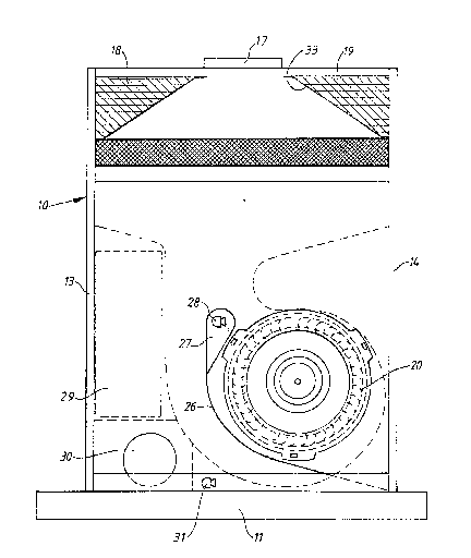
Figure 1 illustrates a front view of the ventilator according
to the invention with the front wall thereof
removed, and
Figure 2 is a vertical section of the ventilator.
The ventilator shown in the drawings comprises a housing 10
which at its lower end has an inlet 11 provided with a so-called
grease filter 12. The housing has vertical side walls 13, 14, a
rear wall 15, and a removable front wall 16 which on its lnside
is provided with a sound absorbing material. The housing has an
outlet 17 provided centrally at the upper end thereof.
A fan 20 having a horizontal axis and powered by an electric
motor 21 is provided at the lower portion of the housing. The
interior of the housiny is divided by means of a vertical
partition wall 22 into an inlet passage 25 disposed in front of
said partition wall and connected to the inlet 11 of the housing,
and an outlet passage 23 disposed behind the wall and connected

210(S3 ,)1~
to the outlet 17. The ~an 20 is provided behind the wall 2Z and
has an inlet connected to a corresponding opening therein. The
outlet passage 23 is provided at its upper portion with a
bracket 32 for an odour filter 24 which is removable and can be
used optionally. The odour filter preferably contains active
carbon and is primarily intended to be used when the air
discharged via the outlet 17 is recirculated, and can be disposed
with when the outlet is connected to an evacuation passage.
Between the air filter 24 and the outlet 17 the outlet passage 23
has a narrowing portion 33 which on both sides has chambers
18, 19 provided with sound absorbing material.
The space in the housiny 10 in front of the partition wall 22
formes an inlet passage 25 extending from the enlet 11 to the
fan 20. In this space a baffle wall 26 extends from one side of
the inlet 11 and partially around the fan to the same level as
I the top portion thereof. The object of the baffle wall is to
¦ screen off the fan nolse from the lnlet 11 of the housing. The
1 upper end of the baffle wall ls rounded and surrounds a
I chamber 27. Air entering the inlet 11 flows upwards throuyh the
1 20 housing on the left side of the baffle wall 26 and around the
! upper end thereof to the fan 20. The inlet passage 25 has a
! relatively large area which results in a low flow velocity and
consequently a low noice level.
In order to reduce low frequency noice the ventilator is
provided with means for active silencing of noice comprising a
first acoustic sensor 28 provided in the chamber 27 and sensing
the fan noise ln the vlcinity of the fan inlet. The signal from
the sensor 28 is processed in an electronic control unit 29
controlling a loudspeaker 30 provlded adjacent the inlet 11 of
the housing. The loudspeaker emits a sound which is phase shifted
in such way as to be in reverse phase relative to the sound
sensed by the sensor 28 which is thereby actively silenced. A
second acoustic sensor 31 is provided in the inlet passage 25
adjacent the inlet 11 and is equally connected to the control
unit 29. By ~eans of this second sensor it is monitored that the
sound emitted by the loudspeaker 30 has the correct character and
phase shift in order that the sound sllenclng operates in the
intended manner. If thls should not be the case, the control unit
performs a required correction in response to the signal received
~ ::

2~0(3,j~f3
_~ 3
from the sensor 31, until the desired result is obtained. Low
frequency noice from the fan 20 can therehy be eliminated to a
large extent.
By means of the ventilator described above it has appeared to
be possible to obtain an essPntially reduced noice level without
reducing the capacity.
It is a further essential advantage of the ventilator
according to the invention that it is easily available for
cleaning which important from the viewpoint of fire protection.
By removal of the front wall 16 the inlet passage 25 and the fan
20 are made easily available. ~he :impeller of the fan is easily
removable from the motor 21 whereby the lower portion of the
outlet passage 23 becomes available through the opening in the
wall 22. The top portion of the outlet passage can be made easily
available by removal of the odour filter 24.

Representative Drawing
A single figure which represents the drawing illustrating the invention.
Administrative Status

2024-08-01:As part of the Next Generation Patents (NGP) transition, the Canadian Patents Database (CPD) now contains a more detailed Event History, which replicates the Event Log of our new back-office solution.

Please note that "Inactive:" events refers to events no longer in use in our new back-office solution.

For a clearer understanding of the status of the application/patent presented on this page, the site Disclaimer , as well as the definitions for Patent , Event History , Maintenance Fee  and Payment History  should be consulted.

Event History

Description Date
Inactive: IPC from MCD 2006-03-11
Time Limit for Reversal Expired 1997-10-15
Application Not Reinstated by Deadline 1997-10-15
Deemed Abandoned - Failure to Respond to Maintenance Fee Notice 1996-10-15
Application Published (Open to Public Inspection) 1994-05-04

Abandonment History

Abandonment Date Reason Reinstatement Date
1996-10-15
Owners on Record

Note: Records showing the ownership history in alphabetical order.

Current Owners on Record
AKTIEBOLAGET ELECTROLUX
Past Owners on Record
LENNART WILHELM CASTWALL
Past Owners that do not appear in the "Owners on Record" listing will appear in other documentation within the application.
Documents

To view selected files, please enter reCAPTCHA code :


To view images, click a link in the Document Description column. To download the documents, select one or more checkboxes in the first column and then click the "Download Selected in PDF format (Zip Archive)" or the "Download Selected as Single PDF" button.

List of published and non-published patent-specific documents on the CPD .

If you have any difficulty accessing content, you can call the Client Service Centre at 1-866-997-1936 or send them an e-mail at CIPO Client Service Centre.


Document
Description 
Date
(yyyy-mm-dd) 
Number of pages   Size of Image (KB) 
Drawings 1994-05-03 2 107
Abstract 1994-05-03 1 38
Claims 1994-05-03 1 65
Descriptions 1994-05-03 3 175
Representative drawing 1999-07-11 1 30
Fees 1995-10-03 1 62