Note: Descriptions are shown in the official language in which they were submitted.
.1_
r~~~~~~
COMPACT WRIST TELEPHONE
Technical Field
This invention relates to a portable telephone device and, in
particular, to a telephone device that is worn on a wrist or as a timepiece.
~a,ck~round of the Invention
Advances in microelectronics have made portable telephones a
reality. Initially, portability meant that telephones could be installed in an
automobile which was linked to a telephone switching office over radio
waves. The equipment needed to support such a portable telephone was far
too heavy to be conveniently carried by a user, but the desire for greater
portability remained unabated. Cordless telephones represented a nearly
simultaneous development wherein the user was able to remove the
telephone handset from its normal resting place (a telephone base) and then
roam around his/her house, during a telephone conversation, without being
constrained by a cord that tethered the handset and base together. More
recently, Motorola and other companies have introduced very light (less
than 8 ounces) personal telephones that can be easily carried in the user's
pocket and used for bidirectional telephone conversations over radio waves.
Continued advances in microelectronics have finally made it possible to
build telephones that are the size of wristwatches.
Perhaps the earliest disclosure of a compact portable telephone
was the ~~two-way wrist radio' shown in the ~~Dick Tracy ~ comic strip.
Here, a wristwatch functioned as a hands-Free telephone (i.e., Dick Tracy
spoke directly at the wrist radio during transmission, and listened to a
receiver on its face during reception). Unfortunately, details regarding the
construction of such a device were not revealed in any of the comic strips.
One of the problems associated with this kind of design comes from
unwanted acoustic coupling between the receiver and the microphone which
leads to oscillation (sometimes called ~~singing~~) in extreme cases. This
condition places undesirable limits on microphone sensitivity and~or ~ .
receiver loudness.
One solution to the acoustic coupling problem is found in U.S.
Patent 5,121,426 which teaches the use of a directional microphone and the
advantageous positioning of a receiver in the null of its directivity pattern.
~,7. 1 ~ '
~.~~9P9e~~,~
-2-
This solution may be augmented by the addition of an acoustic echo
canceler. And while this solution is quite effective, it is desirable to
further
decrease acoustic coupling between the microphone and receiver
transducers.
Another solution to the acoustic coupling problem is found in
U.S. Patent 4,848,818 which discloses a wristwatch having a pair of straps --
each terminating in a clasp. The clasps interconnect with each other to
fasten the straps to a user's wrist. A microphone is mounted within one of
the clasps and a receiver is mounted within the other, so that when the
wristwatch is unstrapped from the user's wrist it may be used as a
telephone handset. While this technique advantageously separates the
physical distance between the microphone and the receiver to accommodate
the distance between the user's mouth and ear, the strap must be relatively
stiff so that it can be easily held in place during a telephone conversation
which limits the kind of straps that can be used. Furthermore, it is
desirable to minimize the number of components installed in the strap
because it increases the complexity of the manufacturing process. (Consider
the problem of extending wires through the strap to connect the receiver
and microphone to the case where the other electronics are located.)
Nevertheless, this technique addresses the need for proper .modal distailce.
The modal distance of a telephone handset is measured from the
center of its transmitter port, with the handset held in a prescribed manner,
to a mouth reference point. Since it is desirable to deliver a fixed output
signal level to the telephone line, changes in modal distance need to be
compensated 'by changes in transmit path gain. However, increasing the
amplification in the transmit path also increases any background noise
picked up by the transmitter and the resulting signal-to-noise ratio is
reduced. And although it may be desirable to avoid using the straps of the
above-identified patent to achieve modality, reducing the spacing between
the receiver and the microphone will degrade the signal-to-noise ratio and
increase the likelihood of feedback from the receiver to the microphone.
Whereas there are a number of known constructions of
wristwatch telephones, none are completely satisfactory insofar as modal
distance and compactness are concerned. In fact, improving modal distance
usually comes at the expense of compactness and/or convenience. It is,
therefore, desirable to provide a compact telephone that avoids the cited
-3-
disadvantages of known wristwatch telephones.
Summary of the Invention
In accordance with the invention, a compact wrist. telephone
includes a case having an upper member which is hinged along one of its
sides to a corresponding side of a lower member so that it has a closed
position and an opened position. A receiver is embedded within one of the
members and a microphone is embedded within the other. By such
positioning of the microphone and receiver, the distance between there is
substantially increased when the case is in the opened position.
Accordingly, modality is improved without sacrificing compactness.
In an illustrative embodiment of the invention the distance
between the microphone and the receiver, even in the opened position, is
less than the distance between the user's mouth and ear; however, a highly
directional microphone is used to compensate for non-modality in this
situation. The wrist telephone further includes a keypad and a display
within the lower member, and a watch bezel is used as the upper member.
The bezel comprises a glass area surrounded by a metal or plastic rim which
includes a first region for holding the receiver on the side opposite its
hinge.
Similarly, the lower member includes a second region for holding the
microphone on the side opposite its hinge. By locating the microphone and
receiver away from the hinge, the distance between these transducers is
increased when the case is opened. Furthermore, when the case is closed,
the first and second regions overlap each other so 'that the upper and lower
members form a compact structure.
In another illustrative embodiment of the invention, the compact
telephone is incorporated into a timepiece that may be carried in the user's
pocket or purse, or it may be attached to a necklace and worn around their
neck.
Brief Descr_ ipt'ion of the Drawing
The invention and its mode of operation will be more clearly
understood from the following detailed description when read with the
appended drawing in which:
FIG. 1 is a perspective view of a case for a compact wrist
telephone shown in its opened position;
_4_
FIG. 2 discloses the compact wrist telephone of FIG. 1, shown
with attached straps and in its closed position;
FIG. 3 discloses a second embodiment of the invention in the
form of a pocket watch;
FIG. 4 is a block diagram of circuitry used in the compact
telephone;
FIG. 5 discloses a prior art wrist watch telephone; and
FIG. 6 demonstrates the manner in which the compact wrist
telephone of the present invention is held during a telephone call.
Detailed Description
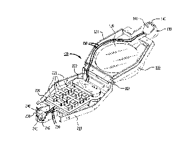
FIG. 1 discloses a case 100 for a compact wrist telephone in
accordance with the invention. The case 100 comprises an upper
member 110 and a lower member 210 which are hinged together by a
hinge 160 along a common side of the case. Various hinging apparatus may
be used including a '°living hinge°° when the upper and
lower members are
made from plastic material. The lower member 210 includes keypad 221
which is used for dialing a telephone number and for controlling the
display 222 which normally shows the time-of day but also shows the dialed
telephone number when used as a telephone. (Because the keys 221 are
relatively small, it is desirable to show the dialed number so that errors can
be spotted.) Whereas raised keys 221 are illustratively shown in FIG. 1, a
preferred embodiment would use membrane-type keys to increase the space
available for electronic components needed to operate wrist telephone.
Keypad 221 and liquid crystal display 222 are mounted on a circuit
board 220. A conventional miniaturized radio transceiver 261,
microprocessor 260, and memory 223 (see FIG. 4) are mounted on the
bottom side of circuit board 220. Although the battery and antenna are
mounted below the circuit board 220, it is the designer's choice whether to
incorporate a flexible battery in the strap.
Of particular importance, however, is the location of the '
microphone and receiver to achieve a significant improvement in modality.
Lower member 210 includes a directional microphone that is mounted in
enclosure 230 which resides on a side of the lower member that is opposite
the side on which hinge :160 is located. Similarly, upper member 110
includes a receiver 140 which is mounted in enclosure 130 which resides on a
side of the upper member that is opposite the side on which hinge 160 is
_5_
located. When the case 100 is opened, the distance between the
microphone 240 and receiver 140 is approximately 85 millimeters.
Referring first to the microphone 240, a suitable device is the EL
Series Hearing Instrument Electret Microphone which is a directional
microphone that is commercially available from ICnowles Electronics, Tnc. A
directional microphone is more responsive to sounds coming from one
direction than from another. Contrasted with directional microphones are
ones that are equally responsive to sounds coming from all directions and
called "omnidirectional°' or °°pressure" microphones. A
microphone that is
responsive to the phase difference between two spatially separated points of
the same sound wave is utilized to achieve directionality. Microphone 240 is
such a device, and includes a pair of input ports 241, 242 for receiving
sounds at two separated points in space. These input ports are tube-shaped
and are oriented in different planes that are perpendicular to each other.
Ports 241, 242 protrude through holes in enclosure 230 which supports the
microphone 240. Wires 250 connect the microphone to the radio transceiver
mounted on the underside of circuit board 220. Alternatively, circuit board
paths may be used in place of these wires.
It is well known that the resulting directivity (polar response
pattern) of a two-port microphone is a function of the distance between
these ports and the manner in which the input sounds are combined (i.e.,
addition, subtraction, delay). In the preferred embodiment of the invention,
a cardioid (i.e., heart-shaped) directivity pattern is used and provided by
the aforementioned EL Series microphone. The cardioid pattern is changed
when the microphone is mounted on a flat surface (i.e., sound waves are
reflected by the flat surface and then combine with the direct sound waves).
Accordingly, when the microphone is held nearly flush with the user's cheek
(see FIG. 6), both direct and reflected sound waves combine to increase
microphone sensitivity because these waves are nearly °°in-
phase.°° In
optimum situations, microphone sensitivity (hence signal-to-noise ratio) is
increased by 6 dB. There is also an approximate 3 dB improvement in
directivity which reduces unwanted sound from directions other than the
user's mouth. It is noted that the receiver is positioned in the vicinity of
the cardioid's null so that sounds emanating from the receiver are not
picked up by the microphone.
-6- ~n.~.U~>.~4J
Upper member 110 is a watch bezel which comprises a glass
surface 120 that is supported by rim 121. Enclosure 130 contains
receiver 140 whose sounds pass through opening 141 in the enclosure. A
suitable receiver is the ED Series Hearing Instrument Receiver which is a
high efficiency device that is commercially available from Knowles
Electronics, Ine. Wires 150 connect the receiver to the radio transceiver
mounted on the underside of circuit board 220.
Illustrative embodiments of the subject telephone are shown in
FIG. 2 and 3 which respectively disclose a wrist: watch and a pocket watch
design. FIG. 2 demonstrates the compactness achieved by the invention
when case 100 is closed. Enclosure 130 which houses the receiver is
designed to overlay the enclosure 240 (see FIG. 1) which houses the
microphone. Straps 310, 320 attach to the case and fasten it to the user's
wrist.
FIG. 3, on the other hand, discloses a slightly different
embodiment of the invention which includes a ring 350 for attachement to a
chain or a necklace. Membrane-type keys 321 are shown in this
embodiment to provide plenty of room within lower member 340 to house
electronic components. Hole 391 in the lower member is used as the
primary input port to the microphone located directly behind it. A
conventional timepiece 351 is shown independently mounted on upper
member 330 which, as in all of the embodiments, is rotatably connected to ,
the lower member. Once again, a hinge is used as the means for
accomplishing this connection. Although not shown, a receiver is mounted
in the upper housing member 330 in the region directly beneath the Roman
Numeral ''VI°' shown on the timepiece. In this embodiment, inter
transducer distances greater than 85 mm are possible because pocket
watches are still deemed aesthetic when they are larger than wrist watches.
Further, virtually any watch style can be mounted on the upper housing
member 330.
FIG. 4 is a block diagram of conventional electronic circuitry
used in wrist watch telephones. Because small batteries are used in such
devices, the electronic circuitry is selected to have low power consumption.
Display 222 is a liquid crystal device (LCD) that is used to display time-of-
day under control of microprocessor 2f~0 which includes permanent °'on
board" memory that defines its tasks and the order of execution. Variable
_7-
memory is stored in memory 233 which, illustratively, is a random access
memory (RAW) that contains changeable information. An example of
changeable information is a speech template which comprises data that is
used to recognize a spoken word. Indeed, it would be highly desirable to be
able to change the time-of-day or to dial a telephone number by merely
speaking an appropriate command into microphone 240 which is interpreted
by the microprocessor in conjunction with data stored in memory 223.
Keypad 221 comprises a plurality of switch contacts which are sequentially
scanned by the microprocessor to determine whether they are presently
being pressed. Keypad information is then forwarded from the .
microprocessor 260 to the radio transceiver 261 which converts same into
radio frequency signals, illustratively, in the fl00 MHz or 1.6 GHz range.
Such frequencies have very short wavelengths and only require short
antennas which may easily installed within the watch straps or in the case
itself. Audio frequency electrical signals are delivered to the radio
transceiver from the microphone 230 and used to modulate a high frequency
carrier signal for transmission via antenna 262 to a distant telephone.
Similarly, high frequency radio signals are received by antenna 262,
demodulated by circuitry within transceiver 261, and converted into audio
frequency electrical signals which are delivered to the receiver 140. Such
radio transmission apparatus is known in the prior art and further details
are omitted for the sake of brevity. FIG. 5 is now discussed as an example
of the prior art in wrist watch telephones.
FIG. 5 discloses a prior art wrist telephone device that is
normally worn on.a user's wrist, but removed for use as a telephone
handset. This particular device is described in greater detail in
U.S. Patent 4,847,818. Briefly, watch case 20 includes manually operable
keys for dialing a telephone number and a display for showing the time of
day. The watch case 20 attaches to the user's wrist via straps 22 and 24
which are fastened together by clasps 21 and 26. Clasp 21 encloses a
microphone which electrically connects to telephone circuitry wlthiIl the
case 20 by means of conductors 23. Similarly, clasp 26 encloses a receiver
which electrically connects to the telephone circuitry within the case by
means of conductors 25. F or a number of reasons it is desirable to avoid
disposing the microphone and receiver on the strap. For example, the
manufacturing process would be made easier if it these transducers could be
disposed within the watch case 20 itself. Additionally, by placing the
microphone and receiver at the ends of the strap, the strap must be
stiffened to allow convenient use as a telephone handset. This prior art
device offers "modal" separation between the receiver and microphone,
which is to say that it matches the distance between the user's ear and
mouth. This is a desirable characteristic because it minimizes the demands
on microphone sensitivity and receiver power. Additionally, undesirable
acoustic coupling between the receiver and microphone is reduced when
they are separated. Nevertheless, it is desirable to improve this prior art
design by making it more compact while preserving its modality.
Heretofore, such opposing requirements have been incompatible with each
other.
Finally, FIG. 6 illustrates the convenient manner in which the
compact telephone of the present invention is used. In this illustration, the
wrist watch of FIG. 1 and 2 is unstrapped from the user's wrist and its case
is opened. The upper member 130 of the case contains the receiver which is
held close to the user's ear. The lower member 230 of the case contains the
microphone which, although somewhat distant from the user's mouth, is
designed to be more responsive to sounds coming from the direction of the
user's mouth than from other directions. Unlike the prior art of FIG. 5,
straps 310, 320 need not be held in any particular position during the
conversation. Although it may take some time for users to understand that
they don't have to speak directly into the microphone in order to be heard,
they will undoubtedly be reassured by the distant party that they are being
clearly heard.