Language selection

Search

Patent 2109068 Summary

Third-party information liability

Some of the information on this Web page has been provided by external sources. The Government of Canada is not responsible for the accuracy, reliability or currency of the information supplied by external sources. Users wishing to rely upon this information should consult directly with the source of the information. Content provided by external sources is not subject to official languages, privacy and accessibility requirements.

Claims and Abstract availability

Any discrepancies in the text and image of the Claims and Abstract are due to differing posting times. Text of the Claims and Abstract are posted:

  • At the time the application is open to public inspection;
  • At the time of issue of the patent (grant).
(12) Patent: (11) CA 2109068
(54) English Title: PROCESS FOR OPERATING PERMANENTLY EXCITED SINGLE-PHASE ALTERNATING CURRENT MACHINES
(54) French Title: METHODE DE FONCTIONNEMENT DE MACHINES A COURANT ALTERNATIF MONOPHASE ALIMENTEES EN PERMANENCE
Status: Term Expired - Post Grant Beyond Limit
Bibliographic Data
(51) International Patent Classification (IPC):
(72) Inventors :
  • FEHRINGER, RUDOLF (Austria)
(73) Owners :
  • VOITH TURBO GMBH & CO. KG
  • J.M. VOITH GESELLSCHAFT MBH
(71) Applicants :
  • VOITH TURBO GMBH & CO. KG (Germany)
  • J.M. VOITH GESELLSCHAFT MBH (Germany)
(74) Agent: GOWLING WLG (CANADA) LLP
(74) Associate agent:
(45) Issued: 2001-08-14
(86) PCT Filing Date: 1992-04-28
(87) Open to Public Inspection: 1992-11-12
Examination requested: 1999-03-19
Availability of licence: N/A
Dedicated to the Public: N/A
(25) Language of filing: English

Patent Cooperation Treaty (PCT): Yes
(86) PCT Filing Number: PCT/AT1992/000060
(87) International Publication Number: AT1992000060
(85) National Entry: 1993-10-22

(30) Application Priority Data:
Application No. Country/Territory Date
A 892/91 (Austria) 1991-04-29

Abstracts

English Abstract


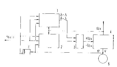
The aim of the invention is to obtain a process for operating a perm-
anently excited single-phase alternating current machine which allows opti-
mal exploitation of the machine and economical design of the converter.
The process of the invention is characterized in that the effective value of a
phase current i of the alternating current machine at maximum torque can
be minimized by impressing certain shapes of a terminal voltage u, using a
converter. The optimal voltage shape, eg., sinusoidal, square wave or
mixed, is chosen in function of the operating range of the machine. The
process of the invention makes it possible for the first time to use a conver-
ter of economical design to supply a permanently excited single-phase al-
ternating current machine, such as a transverse flux machine, and in so do-
ing to turn all the advantages of this machine to account is a wide range of
applications.


Claims

Note: Claims are shown in the official language in which they were submitted.


CLAIMS
1. Process for operating a permanently excited single-phase alternating
current machine, the process comprising:
applying a terminal voltage (u) by means of a frequency converters, said
terminal voltage (u) having sinusoidal components and regions between first
and second switch-over times (.delta.-.DELTA., .delta. + .DELTA.), within
which said terminal voltage
(u) assumes the maximum value of an available voltage,
wherein the effective value of a phase current (i) of the alternating
current machine can be minimized whilst the torque is at a maximum.
2. Process according to claim 1, wherein the terminal voltage (u) has a
square wave form, the terminal voltage (u) assuming the maximum value of the
available voltage.
3. Process according to claim 1, wherein the terminal voltage (u) has a
sinusoidal wave form.
4. Process according to claim 1, further comprising:
feeding angle of rotation (.omega.) of said alternating current machine, a
circuit
frequency (~), a preselected moment (m soll), and an intermediate circuit
voltage
(U zk) into first and second control devices;
calculating, in said first control device, switch-over times (.delta.-.DELTA.,
.delta. + .DELTA.) for
switching over to an intermediate circuit voltage ( + U zk) or (-U zk),
according to
the polarity of the voltage within the half-period;
passing said switch-over times (.delta.-.DELTA., .delta. + .DELTA.) to a
trigger device
corresponding to a voltage source inverter; and
forming, in said second control device, a reference terminal voltage (U soll)
which supplies said trigger device of said voltage source inverter.

Description

Note: Descriptions are shown in the official language in which they were submitted.


l
~°'
2109068
- Process for oberatina permanently excited single-phase
alternating current machines
The invention relates to a process for operating permanently
excited single-phase alternating current machines.
One embodiment of a permanently excited single-phase
alternating current machine is the transverse flux machine.
These machines are permanently excited synchronous machines
with a high power density combined with very low losses from
the armature winding. Powered by inverse rectifiers, these
machines will in the near future probably replace the direct
current drive in many and varied fields of application, such
as direct drives with a very high power density, traction
drives with the correct distribution of drive momentum to
various drive assemblies and with a high level of efficiency,
and linear drives.
The principle of the transverse flux machine is based on the
fact that, due to the special layout of the magnetic circuit,
the usable flux runs transverse to the direction of motion.
The forms of the armature winding thereby possible - annular
windings in the circumferential direction - permit a high
power density with a small armature through-flow and a small
pole pitch. This results in very minor losses, which
increases efficiency and substantially simplifies cooling of
the machine. The transverse flux machine has a further
advantage in the field weakening range, where, with a
constant power supply, a Large r.p.m. range can be covered.
In the field weakening range of a transverse flux machine,
the range referred to is the one where the internal voltage
of the machine exceeds the intermediate circuit voltage.
In DE - OS 37 05 089 ~1, a circuit concept for the power
supply of a double-strand transverse flux machine is

2109068
2
described. The inverse rectifier here consists of two
4-quadrant plates. The inverse rectifier is timed in pulsed
mode operation in order to adapt the voltage. The direct
current can therefore be obtained from the three-phase mains
via an unregulated converter. If accelerated commutation is
desired, avoiding pulsed mode operation, the circuit has to
be enlarged. A direct current actuator controls the
effective voltage in the working phase. The level adjuster
forms the commutation voltage which is applied to the inverse
rectifier via the direct current actuator. The level
adjuster can in this case adjust the commutation voltage as a
function of various parameters, such as the r.p.m. or load
current, for example.
The disadvantage of this circuit concept is that an
economical arrangement of the frequency converter and optimum
adaptation to user requirements, exploiting all the
advantages of the transverse flux machine, are not possible.
Specifications JP-A 54 050 830 and JP-A 61 039 885 each
describe processes which operate either with a square or
with a sinusoidal wave form, corresponding to the
working point of the machine, and JP-A 61 039 885 has
currents to be impressed, whilst in JP-A 54 050 830 it
is not clear whether the voltages or the currents are to
be impressed.
EP-A 0 295 710 describes a synchronous machine operated
by means of a shaft encoder, the time in which the
machine produces a curved form, i.e. the sinusoidal
components of the curve, being used to measure the
operating state of the machine. From this, the form of
the square voltage to be supplied by the inverse
rectifier is then calculated.
The object of the invention is therefore to create a process
for operating a permanently excited single-phase alternating
current machine which permits both optimum use of the machine
and an economical arrangement of the frequency ccnverter.

~' 3 2109068
The object is achieved by the invention. This process is
characterised according to the invention in that, by impressing a
terminal voltage (u) by means of a frequency converter -
the terminal voltage (u) having sinusoidal components
and regions between first and second switch-over times
(8-D, d+c~), within which the terminal voltage (u)
assumes the maximum value of the available voltage - the
effective value of a phase current (i) of the'
alternating current machine can be minimised whilst the
torque is at a maximum.
With the invention of this process, it is possible for the
first time to use frequency converters designed with economy
in mind for supplying a permanently excited, single-phase
alternating current machine, such as a transverse flux
machine for example, and at the same time to exploit all the
advantages of this machine for a wide variety of
applications.
In an improvement of the invention the terminal voltage has a
square shape, the terminal voltage assuming the maximum value
of the available voltage. The advantage of this improvement
is that it offers for the first time the possibility of
minimising the phase current at maximum torque even in the
field weakening range of the machine. This makes it possible
to optimise the layout of the frequency converter also.
According to an embodiment of the invention, the terminal
voltage has a sinusoidal form. The advantage of this
embodiment is that even in the basic r.p.m. range of the
machine the ratio of the phase current to the torque is
optimised.
In a special embodiment of the invention, the alternating
current machine is a transverse flux machine, and a measured
value for the angle of rotation of the alternating current
machine, a circuit frequency forming a differentiating
control circuit member from the angle of rotation, a
preselected moment, and an intermediate circuit voltage are
each capable of being fed into a first and second control
device, and the first control device calculates switch-over

2109068
4
_ --times for switching over to an intermediate circuit voltage,
according to the polarity of the voltage within the
half-period, and passes these switch-over times to a trigger
device of an inverse rectifier, and the second control device
forms a reference terminal voltage and thus supplies the
trigger device of the inverse rectifier. The~.advantage of
this special embodiment is that the curve of the terminal
voltage of the machine is optimised as a function of the
preselected moment by reference to the inverse motor model in
order to generate current. This permits exact adaptation of
the machine to the requirements of the respective field of
use.
Figures 1 to 3 and 5 show the various wave forms to be impressed,
and Fig. 4 an embodiment of the invention in the form of a block
circuit diagram.
The same reference numbers are used in Figures 1 to 3 and 5. On
the abscissa in each case the standardised time t is plotted,
which is calculated from the angle of rotation cp multiplied
by the pole pair number p. Tire ordinate in each case has a
standardised scale extending from -1.00 or -1.50 through 0 to
+1.00 or +2.00 respectively and applies both to the impressed
terminal voltage a and to the phase current i and the
internal voltage of the machine ui. The value for the
intermediate circuit voltage U=k in each case lies at +1.00.
In each case only the positive half-wave is shown, as the
same curves obviously apply to the negative half-wave.
Fig. 1 shows the overdrive range of the machine. It shows
the impressed terminal voltage u, which sinusoidal components
and a range between the switch-over times 3-:1 and d+p, where
the voltage assumes the intermediate circuit voltage U~k. The
essential point is that the terminal voltage a does not
simply run into the inter:.~,ediate circuit voltage U'X, but has
to assume the maximum value at the specified switch-over time

2109068
The phase current i shown here is thus kept to a
minimum.
The terminal voltage a shown in Fig. 2 applies to the field
weakening range of the machine. The optimum curve of the
terminal voltage a is square. By minimising the phase
current i in this operating range of the machine, it is
possible to optimise the layout of the frequency converter
also.
The terminal voltage a in Fig. 3 is sinusoidal and is the
best wave form for the basic r.p.m. range of the machine.
Thus in this operating range of the machine also, it is
possible to minimise the phase current, which gives a very
favourable ratio between the phase current and the torque.
Fig. 4 shows the block circuit diagram of one embodiment,
wherein the electric machine 5, a transverse flux machine,
supplies the measured value, ''angle of rotation". This
measurement is converted in a differentiating control circuit
member 6 into the circuit frequency w. The angle of
rotation ~p, the circuit frequency w, the preselected moment
msoll~ and the intermediate circuit voltage UZk are each fed
into the first and second control device 1, 2. The first
control device 1 then calculates the switch-over time 6-.1 or
~+J for the intermediate circuit voltage -UZk or +UZk,
according to the polarity of the voltage within the
half-period. These switch-over times ~-:1, s+D are then
passed on to the trigger device 3 of the inverse rectifier 4.
The second control device 2 carries out the voltage formation
by means of a calculation, -.with reference to the inverse
motor :yodel and as a function of the preselected moment msoll,
and likewise feeds this to Lhe trigger device 3 of the
inverse rectifier =.

2109068
On the other hand, the process according to the
application envisages a mixed form, both sinusoidal and
square, of voltage to be impressed, the effective value
of the current being minimised by making the voltage
time faces of the terminal voltage to be impressed and
the sinusoidal terminal voltage conceived as being
continued without limit, equal.
If the switch-over times are each at the~cross-over of
the voltage, the terminal voltage to be impressed is
then purely square, but if the two switch-over times
coincide at the apex of the sine curve, then a purely
sinusoidal terminal voltage is obtained.
3
.y

Representative Drawing
A single figure which represents the drawing illustrating the invention.
Administrative Status

2024-08-01:As part of the Next Generation Patents (NGP) transition, the Canadian Patents Database (CPD) now contains a more detailed Event History, which replicates the Event Log of our new back-office solution.

Please note that "Inactive:" events refers to events no longer in use in our new back-office solution.

For a clearer understanding of the status of the application/patent presented on this page, the site Disclaimer , as well as the definitions for Patent , Event History , Maintenance Fee  and Payment History  should be consulted.

Event History

Description Date
Inactive: IPC expired 2016-01-01
Inactive: Expired (new Act pat) 2012-04-28
Inactive: IPC deactivated 2011-07-27
Inactive: IPC from MCD 2006-03-11
Inactive: First IPC derived 2006-03-11
Grant by Issuance 2001-08-14
Inactive: Cover page published 2001-08-13
Pre-grant 2001-05-02
Inactive: Final fee received 2001-05-02
Notice of Allowance is Issued 2001-02-23
Letter Sent 2001-02-23
Inactive: Approved for allowance (AFA) 2001-02-08
Amendment Received - Voluntary Amendment 2001-01-10
Amendment Received - Voluntary Amendment 2000-11-21
Inactive: S.30(2) Rules - Examiner requisition 2000-08-17
Letter Sent 1999-08-05
Inactive: Single transfer 1999-06-28
Amendment Received - Voluntary Amendment 1999-04-30
Inactive: RFE acknowledged - Prior art enquiry 1999-04-01
Inactive: Status info is complete as of Log entry date 1999-04-01
Inactive: Application prosecuted on TS as of Log entry date 1999-04-01
Request for Examination Requirements Determined Compliant 1999-03-19
All Requirements for Examination Determined Compliant 1999-03-19
Application Published (Open to Public Inspection) 1992-11-12

Abandonment History

There is no abandonment history.

Maintenance Fee

The last payment was received on 2001-03-27

Note : If the full payment has not been received on or before the date indicated, a further fee may be required which may be one of the following

  • the reinstatement fee;
  • the late payment fee; or
  • additional fee to reverse deemed expiry.

Patent fees are adjusted on the 1st of January every year. The amounts above are the current amounts if received by December 31 of the current year.
Please refer to the CIPO Patent Fees web page to see all current fee amounts.

Owners on Record

Note: Records showing the ownership history in alphabetical order.

Current Owners on Record
VOITH TURBO GMBH & CO. KG
J.M. VOITH GESELLSCHAFT MBH
Past Owners on Record
RUDOLF FEHRINGER
Past Owners that do not appear in the "Owners on Record" listing will appear in other documentation within the application.
Documents

To view selected files, please enter reCAPTCHA code :


To view images, click a link in the Document Description column. To download the documents, select one or more checkboxes in the first column and then click the "Download Selected in PDF format (Zip Archive)" or the "Download Selected as Single PDF" button.

List of published and non-published patent-specific documents on the CPD .

If you have any difficulty accessing content, you can call the Client Service Centre at 1-866-997-1936 or send them an e-mail at CIPO Client Service Centre.


Document
Description 
Date
(yyyy-mm-dd) 
Number of pages   Size of Image (KB) 
Claims 2001-01-09 1 35
Claims 2000-11-20 1 37
Abstract 1995-07-28 1 88
Claims 1995-07-28 2 55
Drawings 1995-07-28 3 34
Description 1995-07-28 6 288
Description 1999-04-18 6 253
Drawings 1999-04-18 4 35
Representative drawing 1998-12-13 1 3
Representative drawing 2001-07-30 1 5
Reminder - Request for Examination 1998-12-29 1 116
Acknowledgement of Request for Examination 1999-03-31 1 173
Courtesy - Certificate of registration (related document(s)) 1999-08-04 1 140
Commissioner's Notice - Application Found Allowable 2001-02-22 1 164
Fees 2003-04-14 2 70
PCT 1993-10-21 34 1,016
Correspondence 2001-05-01 1 29
Fees 2001-03-26 1 24
Fees 2002-04-11 1 32
Fees 1998-03-31 1 34
Fees 1999-04-11 1 26
Fees 2000-03-23 1 25
Fees 2004-04-19 2 63
Fees 2006-04-19 2 66
Fees 2007-04-04 2 70
Fees 2008-09-22 1 29
Fees 1997-03-23 1 33
Fees 1996-04-11 1 31
Fees 1995-03-22 1 41
Fees 1994-02-13 1 30