Note: Descriptions are shown in the official language in which they were submitted.
2I0916~
The invention concerns a rotary intaglio printing machine
and a rotary intaglio printing process.
A rotary intaglio printing machine, and a process for rotary
intaglio printing, as described for example in Gernian patent
specification No 3 5 30 561, involve passing a web of paper to be
printed upon through at least two printing mechanisms, with a drying
device arranged between the printing mechanisms, for successively
applying at least two inks to one and the sane side of the web of
paper as it passes through the machine. In order to provide for
mufti-ink or mufti-color printing on the web of paper, each printing
ink has its own printing mechan,~sm. The main car~ponents of each such
printing mechanism are a rotary plate cylinder which dips into an
ink trough or fountain and against which the web of paper, as it
passes through the printing mechanism, is pressed by means of a
rotating impression cylinder. The plate cylinder and the co-
operating impression cylinder form therebetween a gap or nip which
is referred to herein as the printing nip. The web of paper is fed
to the printing nip of the printing mechanism from above. The web of
paper is guided and changed in its direction of n.ui, by means of
guide spindles. Downstream of each printing nip, the web of paper
must pass through drying devices as, u.~like the situation in offset
printing, the rotary intaglio printing process provides that the
freshly applied ink is very substantially dried before the next ink
is applied to the web of paper. The drying devices may be formed by
drying cylinders, as in C~ezman patent specification No 35 30 561, or
by drying chambers which, particularly in modern machines which are
operated at high speeds, are of considerable length so that each
portion of the web of paper to be dried spends a sufficiently long
residence time in the interior of the drying chambers. Irrespective
of the specific configuration of the drying device, the web of paper
is also guided in each of those regions by means of a plurality of
guide and direction-changing rollers which are referred to herein
1
' :'.L '!, ..:yl ;H . .1...
1. ;~': Jy. ' . J . %: . r., ,
'.; ~ S
' r.
' .
: '
! ;1V
~ /
Z
~
~
.. ~ .
. ;
. ,...
J .
n. . .,
. .4 J
..'~,~ -r.t . , r, .. ~
u :' :r. 5.... r i:i...~ lYb 1. , , '.4,:.
~ !~ ;: r ,L ~ r 1,!fx.. ...
. f, .t ,.. f ! ..: : Ir . ., 1 .:.; i
.s ~;1;~....
:r
::
a
~
t
. ,
a.i... .
;y ..
: s .. ., ..
~ ;,r
.., ,~~..,::
~, :T'::'J p h. ....v ..
": r ~' f :~r~2~ .v...>; : 'a:~ ~
'!' : u:
.
~
~
. .
.. ,Sr, , r:
,, !y.- .
S'i": v
. . ~
.
, .Y
.f~:1 n..r at
. .- !
' +
t
'
~ , .
h t
~ ,
y r ;
t.
l
,
~ r A ~
...~ ~ ~
.;
~
!'i, .c'..4
:.1 ~ ar
,. 1 ~~ ;tr
1 '
~
~
~
':~ Y
' ' k ..
~ .t.
S : tf
.:.:F'~";a ,,. ! m :'~ ., , t -~"r 4 ;.,
i~.:
:". sex
r . ... ~ :
'p
. J
.
. J
~ I 1 .,
J s.
'~ .!
YJ: f ' :1 PV .
.
r...i
a 2* . ,4 ' ! : i
'~r l
' ,
:'' : ..
, ,
~;
'
4
.,. 1
,...e Y .;
.. . .... ,.
;' ; , ,
r f:
T .! :."!
r
1
~
'
-
,
f , .
' ,
;.: .' ,
': C:
' J
. , F,
' .: .:
:.ii~4 - n . ,! ". a
.
..
:~
:
Y t
'
. . ,
.. ,.
. ,. ..;
. , .
: :
r .sr ,
. . ',..,, .. . 4 , .. .. . .. '
v ., ~
. ~, E ) .. ~ r .',rx . . .
1,~ '
\~, ~
'
'
'
'
. ,
. . ..
.!. :; j >
,a . S..n >. ,
,:
,1 - .\
:~ ' 5r ,. ! :~; _ f':
S- !
:,<
y n
~
,
,..,
2.. .
< .. ..
~e t ;.. ~ . W
-n L.....,,. a ~.:o ~., n: ~i~.w,. ,-f. i , o.S
. ,.a',
.r y1 .
.
w ~
x
'
~
'
~
. .,
. ;i, ,,
r ;; ..
.. . . . ..,v.. , vt. .,
"i: . ~y:y
.:
. ,S . <
n..
>..4 ,.
. . ,. :.'"Y:.,.:, ..~asz .r.;>~r: . ., . ..~ . .
.,.. . .. . ,. .... . ...~. ~. . . - . .
c
generally as guide spindles.
As for example eight printing mechanisms are required for
printing in four colors ~on both sides of a web of material, and each
of the printing mechanisms includes typically between about seven and
ten guide spindles, the previous rotary printing machines suffer from
a series of difficulties:
Thus for example a major problgn is that none of the many
guide spindles has its own drive means, but each is driven in rotation
by the web of paper to be printed upon. The result of that arrangement
is that a large amount of wastage is produced at each change in speed
of the machine, in particular when the machine starts up and stops.
More specifically, when for example, the web of paper is accelerated,
the guide spindles exert a retardation effect while when the web of
paper slows down, the guide spindles have a tendency to continue to
rotate at their previous high speed so that they first have to be
retarded by the web of paper. Accordingly, when there is a change in
the speed of movement of the web of paper through the machine, a
period of time elapses before the newly intended stable condition is
reached, in which the register condition of the web of paper can be
regulated with the required degree of accuracy. All of the paper which
is in the machine and which passes into the machine in such a
transitional period is printed upon with an inadequate degree of
register accuracy, and is therefore not suitable for use.
Particular prolens arise if the machine has to be stopped very
quickly for example because of a fire or because the web of paper
tears. Not least because of the enormous size of the conventional
rotary intaglio printing machines which are more particularly suitable
for printing in four colors on both sides of a web of paper however
malfunction situations of that kind are not infrequent and, depending
on the printed item being produced, an mount of wastage of between 6$
and 10$ generally has to be tolerated.
2
According to the present invention, in a first~aspect, there
is provided a rotary intaglio printing machine canprising at least
first and second printing mechanisms each including a plate cylinder
and an impression cylinder, and a drying means arranged between the
printing mechanisms, a web to be printed upon passing through the
printing mechanisms and the drying means therebetween for successively
printing at least first and second inks on the same side of the web,
the at least first and second printing mechanisms being so arranged
that the web is guided by the plate cylinders and impression cylinders
of said printing mechanisms in a straight line from the preceding
printing mechanism through the drying means to the following
printing mechanism, with the printing side of the web caning into
contact only with the plate cylinders.
The invention also provides, ~in a second aspect, a rotary
intaglio printing process in which a web of paper to be printed upon
passes through at least two printing mechanisms for successively
applying at least first and second inks to the same side of the web of
paper, and in which a drying operation is effected between said
printing mechanisms, wherein the ink which is applied to the web in
the upstream one of the printing mechanisms is dried only to such an
extent that at least substantially wiping-resistant printing is ~
possible in the following printing mechanism, and the web of paper is
guided fran the printing nip of the upstream printing mechanism to the
printing nip of the following printing mechanism in such a way that at
least the side of the web of paper, which is printed upon by the
printing mechanises, remains contact-free.
As will be more clearly apparent fran the following
description of anbodiments of the machine and process according to the
invention, the rotary intaglio printing machine can afford a
substantially higher degree of operational reliability and can be more
responsive to changes in the operating mode thereof, while in addition
3
r ~ ..,, ~ .; .. .
s. .~' ~r,~:~ ~. .
td ,:...
S r
. ,
f ~ t T
~1:'.: ! ~d I.~:
I )' J
S " ~
. t h~ .'. , 1
5..
. . . :4 ' ., 1. .:l:
l1t.Sd... a
~~ " 1. ,w dA
' :'>
-
t . .!. . .,..
. . ~, ~. ., d
;: ~. ~'',.
: : .~,' ~.. :....
. a .
; ~~ -
~
, . :; ;~: , ..,...' ,
. :'.... .~., ..
~ ~ , .
,,. ;, ..
. ,: . ,
' ' r
a ~'
d ~ ~ , ' 1 .
~ I l ~
~~
q
' : . . - ..
.
L ~ , . , .' .: .
.;... ..,.
: . ~ '. '
'
~ J!~
~
.
~ ;
.. ,
~,f.. S , . I _
t -:,,'a' ~ Y ~ .
~. r . ..
~~~ . . :.
., ..,;
, ~., . . . . .
~'..:4.,
~
~
. :' 1 , , .
!y~, < .~ t
.. ,. s.. ..'. .. ": t.f~, .H:'
5~ ' ,:i: .-.. ..,:'. . , 7 .::.~.,.,. ... . '-S'.....,-. ..
~ w ' :.. _....:.
' .. . '
' r
~
, x
.t.,.. 'V.;
... .:
~. ' . ~:.',
S .. '.. ~ ' ;. ' . , . .~ . ,..,:.f. ,
f . ., . ' ..~: .,... m . ::.',
~ ~,.,
.;!
t
.:
- i
t
:
'
'
. .
d ,
tv~ ~. ...
.,. .. , t ;
.. .1' . ~ '~~'.:. '... .... 'w:~ :;',~: ;
,:, m .,,,~,..
.~ >
. , : ~....._..
v . '
a. ;
" . r .:. ..;
being capable of at least substantially reducing the amount of wastage
of paper printed therein and less labor-intensive in terns of machine
operation. The rotary intaglio printing process of the present
invention affords improved printing results with enhanced reliability
and simplicity of operation.
In accordance with the invention it has been found that, with
the intaglio printing inks available nowadays, it is generally
entirely sufficient if the uppernbst or outermost layer of the ink
applied to the web of paper in the respective preceding or upstream
printing mechanism is dried to such an extent as to be wiping-
resistant, that is to say, it cannot be srm,dged, so that the next ink
can then be applied to the web of paper in the downstream printing
mechanism, without problans arising. There is therefore no longer any
need for the ink applied in the upstream printing mechanism to be
canpletely and entirely dried before the next following ink is applied
to the web of paper. Therefore, the drying devices disposed between
the successive printing mechanisms can be of a straight-line
configuration and so short that the guidance effect imparted to the
web of paper by the plate cylinders and the impression cylinders of
the upstrean and downstream printing mechanisms is fully sufficient to
ensure that the web of paper moves in the required direction. There is
no need for the web of paper to be additionally guided between the
printing mechanisms which successively apply printing to the same side
of the web of paper, and in particular there is no need for the web of
paper to be additionally guided in the drying devices between the
printing mechanisms, so that the major part of the above-mentioned
guide spindles which were used hitherto can be anitted. It is in fact
4
2~.Q~~~a~
possible for a rotary intaglio printing machine according to the
invention, which includes eight printing mechanisms, for four-color
printing on both sides of a web of paper, to be equipped overall with
no more guide spindles than are employed in a conventional machine for
a single printing mechanism.
That configuration gives rise to a number of advantages as
follows:
The distance covered by the web of paper within the machine is
considerably reduced in length. As a result, the reliability of the
machine is substantially enhanced, in regard to ensuring that the web
of paper moves in the correct direction as it passes through the ' '
printing machine. The risk of the web of paper tearing is greatly
reduced. If nonetheless such a malfunction situation occurs, the
machine can be stopped much more quickly because the greatly reduced
number of guide spindles store considerably less rotational energy
which has to be converted into heat when the machine is brought to a
halt. In the event of an operational change in the speed of movement
of the web of paper through the machine, the above-mentioned
deceleration effects produced by the guide spindles are also greatly
reduced so that the new set printing speed can be achieved
considerably more quickly. As the length of the web of paper in the
machine at any time is substantially shorter than in the case of a
conventional machine, the anount of paper wastage is greatly reduced
as a result.
The web of paper is subjected to substantially less resistance
and as a result is subjected to less stretching. The degree of
register accuracy is considerably increased in that way.
The energy requirement is greatly reduced because of the lower
levels of frictional losses and the reduced 'stored! rotational energy
of the guide spindles, which would have to be converted into waste
heat when the machine is brought to a halt.
5
. .1': -; : .
<,
~r~;
r
v.;.,k , r,:
~: r.~ ~' .
:. ~,.
..rym ;.... ~
;,,
,. ! i
r
~~,~ ' 1: .xA.
.:~ .a.
r. ;.
n .
r i:'r . C ,
at
. ~.jl .v.. ,
rt. ' ~f ~~ :'
k' r. J . ' >
-
~I ~'~s ~. 'lrd5~r5~
.
'~~:' .r nY .
r~
S.
~
4
~Y
u- ,
f
~
''~.
'
~
f~
~ ~
'
~
~
. .
i : .
. ., ..
.
,
.
,
.
.
.
.
h.. . . . .. . .
. ..
. . (
r .r.. SR .
....1.... . . Y
1. i
if~:. .1;'t.f .. < . ~....
, .. ~
.'. .. ,
K ~.~ ... . . .,.r!"...~LH' '
L
J~
~
. .
.
.,r. ,.
t. .'
r ~
.::. r; .. -I
1 :
.
\ Ya', . ..:. '~ :. f.
.
1~,. 5 r J
..4,
Y ~ 1 ~
u 1l,. i4 -.:" . .1 ':.
~:1 . . ,.r-.Je \". ' .., ..:
~ .. r ". . ,:. , tJ, -i
t ,5.. fn, t..:r .'J.'..
.. . ~ r r r,
. S
.. r
'
~
F
.
'
'Y
l
\
\ ,
" ...
, .
S ; r .
. , f .
...l.,.l.u.. ....
S ',.~ :; .
...r.
. .v. . .r.....
.. ,... ,
.rJ
.,.r.:, ,:.5
-
.9..., ., L.f.,'.~
.: ! . .. J.,. tN.'r.:: .~. -~r
,. tr. ,..5 ' ~'"
l
Y, . .
, ~ .... . 51 . ..
':, fi:"!'. N
, , ,J
:'
'
~
r
~
.
.
.',._., .sr
.fY, :v: r
r , i
;..1. . '.CL
:.1\:. r. .: 1 .
, : r,
\ , r S. . L, SJ
r i! ,... 1 r . ..1. ..,
' ...1.
\
.s
:'
n
~
1
. ..
: . .
. ....1 ..
' r... ,
,. . ..J..
..J J . . l j
....! ...J..
I:I...
'
.1J~- ~ J".. o.y ~ Y ~ >. ...Ir..'..r:r', 1.. ...5....
-l L4 f
.;~ h ..
r
r :
~A :. ,
. l . 7 ~. .
Lf
r
,
~ L
:
~ .
f.~....
' ;
l~ r
.
L
~
:
V. .., .v : 7...
4 " , ; . . .:. . ; , :: .''' ' . .. ~ o .. ,'t :': . '., ,
. :
r..i: r
r \ ,
n .-:, "fir
::. .1. . .",..r~
~.' . ,'Y. . ,.ir-~ ~ .Y r.6~..
.s 4 . ,.vrrt ,
.~eyY~;
..
..:~~r
y
- 3..,.~ ;x .~ .,.,.. ~ ..
.' - c .. .<.
, ~, , r .r;, I
, .. ...::. "...'..~..::-~.. , , ~:~ ...,....... ..:. . ..~ . ..:::v..' -
....
:4~ . ....:. .' .., ...i .. . .:
~
Another major advantage of the fact that the web of paper is
guided in a straight line in a contact-free manner from one printing
nip of a printing mechanism to the next is that in particular the
machine according to the invention does not require the guide spindles
which, in prior machines, are arranged parallel to the plate cylinder
of a printing mechanism, immediately upstream and downstream of the
printing nip thereof. In such a machine, such guide spindles guide the
web of paper which arrives at the printing mechanism from above, for
it to pass through the printing nip, and to deflect it from a
substantially vertical path of movement into a horizontal path of
movement and thereafter back upwardly again. It will be seen therefore
that, in operation, at least one of those guide spindles is
necessarily disposed in the region of the path of movement along which
the plate cylinders must move when for example the plate cylinder of a
printing mechanism has to be exchanged for another plate cylinder, for
example when converting the machine to print a different printed
product. Such a cylinder exchange operation is car~licated by virtue
of the fact that each of the two shaft journals which project beyond
the ends of the plate cylinder for rotatably supporting same are
mounted in a ring bearing arrangement which in turn is carried on the
frame structure of the machine. When replacing a plate cylinder, the
plate cylinder is lifted by means of a special lifting device together
with the twu ring bearings upwardly off the machine frame structure
and then displaced parallel to itself. and transversely to its
longitudinal axis, into the free space bQtween the printing mechanism
of which it is a part, and the adjacent printing mechanism. The ring
bearings are then rgnoved in an axial direction and the plate cylinder
is moved out of the space between the printing mechanisms, by
displacgnent in its lengthwise direction.
Conversely, the fresh plate cylinder to be installed is moved
into the space between the printing mechanisms, in the lengthwise
direction of the cylinder, and, after the ring bearings have been
6
fitted on to its shaft journals, the new plate cylinder is moved
transversely relative to its longitudinal direction into a position
above its actual working location into which it can then be finally
lowered.
It will be seen therefore that, in order to produce those
mcnrements of the plate cylinders, in the prior machine, not only was
it necessary for the respective impression cylinder to be lifted by a
considerable distance to allow the plate cylinder to be re~raved, but
in addition it was also necessary to move away the guide spindle
disposed at the side of the printing mechanism, towards which the
plate cylinder is removed. That operation requires an expensive
mechanism which can be eliminated together with the above-mentioned
guide spindles in a rotary intaglio printing machine in accordance
with the principles of the present invention. That means that the '
structure of the invention also considerably simplifies installation
and removal of the plate cylinders, and makes automation of that
operation more readily available.
In accordance with a preferred feature of the invention, the ..
printing mechanisms for printing on one side of a web of paper are
positioned in vertically superposed relationship in a tower-like
arranganent so that the web of paper can pass perpendicularly
therethrough. That configuration results in the amount of floor space
taken up by such a machine being greatly reduced.
A further advantage of the tower arrangement is that each of
the impression cylinders, in operation, is no longer disposed exactly
,.
above the associated plate cylinder and presses on to same from above.
On the contrary, it is possible for the impression cylinder to be
positioned substantially laterally of the plate cylinder and with its
axis only slightly above the axis of rotation of the co-operating
plate cylinder. As a result, for exchanging the plate cylinder, there
is no need for the impression cylinder to be raised considerably out
;,
ri .. ... .
yr
v'
'Y
11
~,';i.t...
n..,
1
2 ~ ~3~ ~. ~ ~:
of its operating position; instead, it is sufficient for it to be
pivoted slightly away fran 3~he plate cylinder, and a substantially
simpler form of mechanism can be used for that purpose. Accordingly,
the tower-like arrangement of the printing mechanisms also contributes
to greater ease and simplicity in removing and installing the plate
cy:Linders.
In accordance with a preferred feature of the invention, in
order to particularly minimise the height by which the plate cylinder
has to be raised for rerrbval thereof and lowered for installation
thereof, the plate cylinder, instead of being supported by the
hitherto conventional ring bearings for each shaft journal of the
plate cylinder, is supported by a backrest-like or cradle-type bearing
means which thus comprises for example one, two or three support
rollers and which is open upwardly in such a way that the plate
cylinder with its journals can be easily lifted upwardly and forwardly
therefrom to remove the plate cylinder and can be inserted fran the
front and from above of the bearing means, far fitting the plate
cylinder. Such bearing means can be fixedly connected to the machine
frame structure in such a way that they can be displaced to adapt same
to different plate cylinder diameters. The cradle-type configuration
of the support bearing means provides that this eliminates the
operation of withdrawing ring-type bearings fran a plate cylinder
which is to be rgnoved and subsequently re-fitting sane on to the
shaft journals of a fresh plate cylinder to be installed.
In practice, the operations of removing and refitting support
bearing means for the plate cylinder may be effected quite frequently
for the reason that the plate cylinder journals must very accurately
fit into the inner track rice rings of the support bearings so that
they cannot tilt or tip. If the plate cylinder to be installed is only
a few degrees C too hot, which is easily possible by virtue of a
preceding galvanic treatment, the bearing means, because of the radial
expansion of the shaft journals due to the increased tgr~erature
8
.. .v:. ... .~: ,,...~., ,..",, ,~ .~,~.~' t.. :ri , ,,.:.~~r:..... ~~~~
'...'.,.. :;. ~. ° ''~~: , ...: ~...:. ~,..
~. . .' :: ... ~. .,' . . , ..:' t ;,:. .. . '.':. ...: ' .~ 'wr . . .; ~ .:
.. . ,
r r...
~~r . S..~.~i "~:. . t:.'.'
5. , .1..,.. .'t r....
::ft ~.t ~ '.'.~1 . S . . t
;.' h 5 .~: ~ 'h:'. '
L ,:. ...5.:.~"..~'S ~., .. r...n .
f. 1
.
° ~~. ~ ,SY:1'
~K5 , .. ..Y.
1.
~~!i ..f:t .:. ,r
I. :. I tr !: t .'y4v ~SGCf S :..
r. . . ~ . . ~ tt tt .
~.,j.. ~ 3 r ~ ~'
3 ... r- !,. 3' .,
.. I.'e !' I ~ 4.t.. r ~.
. . r 51..rN ~:~ r l'a.5 '.7S-., f r '
...h. ' ~ 4f~~ S : ~ 5
t ...~,~!
r ...
...r . s~.
...t?. .. . )r .
. 3
7 . 1'. ..
.~..i. ~~ , :r3.
., t .~ ,.t~ .. 5
r ...'
,'~l , r . t
4 . . . Y ,. .( ..i rtf ,..
...ri.s: ~. Yr . v, .'.:''::; .Y
..r'.,., : ~ ,..t. . S'
n ~.. o. S. '
!..r. ,...fi.
tl ,
.e ~ , .1
.t ..t . !..\. .r 'tfl'.-:v:
...r~.Y . ...F. t
:."'~S: e.. ..vY ~'
C
..'.55 i .
:~..r . , .~ f r .5
-:'~ ..~ ~. ~ Jh. ~.. ~
P.:~ Ja t. ".; t. .,
' $~: .d:. f
.,.n,.:-. ...:~'/' ~~~.
:: :.S~. : ~ RY. .'~~ ,....~....~ ..f ~.,.5.. .
.a!"d.a~i.., .~..~:.~:.~ .I.
l..'. ....1 . ~s:.C' . . ,5..:..., 5.
...5. .. !M . .:~ . 1;..:
...f.,.l~t L" ~" 'r 'C
... a : t ~.X.~,...
. a:.~. .~ ~~. . a ~"..
JS v. ?'. h ,,.". v....,. 4.
3 S~ ~:' h t,.. .. S :. .. 5..: S
:v. Y.... I .: ~ S . .
N, . ~ . :1' ~'. ...5 , .. .rY ......5'. .1 , .
Yr' ~~., t .".5... ,, ~ . ;A.. Y' .51~ 1 '.:~
.~.... ..~.t.,.' ...5...:
' .1
~f°in: ...S.A ..:
5..,. , .Y. .~..L):...1 , d. ::"
.S~'J .., .. ~ .'.'.t :' :' ~...Ms
Y .. , r " 5 ... .. 1,. ~,.;.
,... . . t. .. . .~.. 5..
",. . .. . ..... . . .... , . .... . .... .,: ~~.!. ~~..... . .... 1,. .......
... .-nn u. .v. ..,r..
21D9164
obtaining, can frequently not be fitted on to the shaft journals until
'the shaft journals have suitably cooled down. All such difficulties
are eliminated when using cradle-type bearings in accordance with
'the invention. As cradle'-type bearings provide that the bearing forces
rnust be carried by a small number of bearing elements for longer
periods of time than in the case of ring-type bearings which are
conventionally used, it was hitherto ass~m~ed,that cradle-type bearings
would heat up excessively, particularly at high speeds of rotation as
are used nowadays in rotary intaglio printing machines, and would not
be capable of supporting a plate cylinder with the required degree of
stability. It has surprisingly been found in practice however that
such fears are unfounded, and it is entirely possible to provide for
adequate cooling for the bearing means and the weight of the plate
cylinder and the pressing force of the impression cylinder are
entirely sufficient to ensure a stable mounting configuration.
A further impediment in the above-mentioned operation of
rEtnoving and installing a plate cylinder, by movement thereof
transversely to its longitudinal direction, was hitherto the doctor
arrangement which, in the prior machines, is so positioned that the
generatrix along which the doctor member is in contact with the plate
cylinder is disposed as closely as possible to the printing nip, that
is to say above the axis of rotation of the plate cylinder. That was
deaned necessary in order to ensure that the printing ink in the
depressions or recesses in the plate cylinder did not dry as it moved
between the doctor manber and the surface of the paper to which the
ink was to be applied. Haaever, that risk no longer applies, not least
because of the high printing speeds of modern rotary intaglio printing
machines.
In accordance with a preferred feature of ~ the machine of the ° a
invention therefore the doctor arranganent is so positioned that the
generatrix along which the doctor blade is in contact with the plate
g
:..1..~'.r ,! :;:1:.'~;:' "iA~'.. . ..
r.i~:. ; :l.S r.
5, , t. ~ . I r l . r::'. ( ri 4 - '
i'~~, ' 1 , r .':
...r '.:! m.~...
en~ . ~,:.: .J~~,..
:..i '~,. . r.'.. ..'i~ .,..
.1. f; ...1., 'a:J::~r::' ~. f:. .'r,
d.....
f r
r .',~!
~.;r:,;.;
~ z .:
:~ r,
-!~ . t, .r,:~ ..Jfl,~ Y~. .
f . .
.., .
.: r,X ..':. .rrr...
. .r . . ,.:.:.r.,... ., ,d. .:.
r , . ~ : i. ~ r ~, ~ " vl..:
l ,..r..vS~~1~~.. ,rJ.O.,5..,.
f. .,.
,~ 7.:~ :'
r.f'
..;l~l': y "
:.I- . '. 'v
....~,u r~7.:~~~ ..tt.,r
J .~' . r..,. ,:'l. . r<":: ~r
.7...:< t.r... ). ..Y
..d,.~. ' ,..d.. .r...
':~.i:'':S 11.. .. .'r '....
,..L',.
.. v. ..
... ,. '~, '. ~ ; .,r . ,
r. i.
~. o .. ~ ':
S J~~~ .A-..
~.,. 1 :,s.i..S;.'l ~ 1. n L:. . , .
m. .. ~, ,
' . 5 .a
4.~:..: L< .'. t.~ '. d ~.~!
. y,h S '~.r .'r r'
i.r I. ..vl:-, A ~A t -. ,.
r;a..~ L ':
1 :, r '.n.': ~:,~t. ~ "~h
f ., 4
: .1 yR, ..,'., - : ~
e~ , r ~' : .. ..~;.r.. ..r...'.
i .
°:a
Y:
1 . ~. 't, ~u ~t..Jr:
Y y..t.
S 1, 1. ~~ t " . . .h.
:...5 ...
J' n
Y ,
J .
./.;.,.. :.,.'~r,;~ .
P 4 ; ~ ::
.. i.. .si:~..
~WL l~:
...1 t ..;~ .w~.;~ xr.:,'-
. k. . 4
a '~ .,..5 ,.
?~~.,
.,td .:
4 ,
.r.: r . . .,.>;~~ ~.
.,
1 . 4.
..Y
.M.:~
:I r,' :.
i
x, r ~l'.
.1,.. ...( J..,
.,. d .. . S
..y" ..;
~:.x.., .. , a , .t
r . f~ '.'
r . .t. ., .rr ~ .. A
r,,
.-. , r . .31;::.~
r.
a. ;. r.:, '.~
... .~..~,~ t '. ,'7. r. .. r S ..
., f ~ .. 1.,.. .. . W
1 ,.. J ~'. °v a. n 1. f.
V ,. ~ ~ ..S . ~0.~'-'
'.:.'t..... :.i.y ,
n. .V...
3z,...
,.; ~fl.'. . r.
y_.,
c
r. .. 4 ':..'
y. ...
.; .... ,r,'t.
~: >--
~J . s'T -
;Sy . .:-'ir c . s .,,
r ~... L : >
. ?.- ,.~, . ~. ~ a.. . E,.
..y...
. t:h.... .
.: ~'i.
.. !.. ..
, 4 : .S .., ~...~:.n
Y
.4. : .'.;
u.. ~ uR.
.w .:
r. .~~.~...:,,a y
1 .
r ~
r ; w x ~ .. ~ '$, . -'S
.t~': ':
... . . ., .. . . . . . .. . . .. ... . t . .511.. .. .r. .....
L ., . . .... ,. . . ... . ......'b..l.. . . .. ........,... ....... . .,L.,..
.'C . .. ... a .... ...
,'--,
21fl9164
cylinder is no higher than, and preferably lower than, the axis of
rotation of the plate cylinder when in its operative position. In that
way the doctor arranger~ent is disposed outside the region through
which the plate cylinder is moved when being removed or installed. The
hitherto canplex mechanism required for lowering the doctor
arrangement and pivoting it out of the way can thus be eliminated and
it is now only necessary to provide means for adapting the position of
the doctor arrangement to different plate cylinder diameters. That
design configuration therefore also contributes to greater simplicity
in the operation of removing and installing the plate cylinder, so
that it can be more easily autanated.
A particular advantage of the above-mentioned tier
arrang~nent of the printing mechanises is that the building in which
the machine is disposed can be in the form of a capsule into which the
web of paper passes through a narrow slot which can be closed and
leaves it again, after the printing and drying operations, through a
preferably oppositely disposed, also narrow slot which can also be
closed.
Encapsulation of the machine in that way permits extrgnely
effective sound-proofing relative to the exterior and permits the
solvent which is given off when the ink or inks dry to be practically
canpletely recovered. As no one has to stay within the encapsulating
enclosure while the machine is operating, the values of maximum
solvent concentration at the working station can be reduced to a
minimum, so that they can be considerably below the permitted levels.
In the event for example of a fire within the encapsulating
enclosure, which can be very easily detected by virtue of the compact,
self-contained arrangement,' it is possible for the web of paper
passing through the arrangement to be autanatically capped at the
entry and exit slots, in order to close off those slots within a very '
short period of time, whereupon the entire encapsulating enclosure can
be flooded with C02 within a few seconds. That can substantially
!r. ;rr:
~. So ...J~'~.~ S ,.,,j. ~ .:::r~
..r. ~ .. I~ " .~ r..:: !
J .:,.r... . ...fn
.. r. . ..
r ,. i,. . :.r.,. . ., ~~~, ...h(
,..1. Y. 5,. ./..
ti...7..r r
. .l',-~..
~! ,7T ...r I% .,
s aI r
..,r:. .. J" ::~5
"J. , x ~:r.Jv "!. r tS~:: . ...~.... ,. ..,
,fx~
' 3., ..:.t..i':.
r
4 .:.
..~.. r
-.= r ,.. : k r-. .
.z
'rr:'~~ !
. . S . "r S
,l:. , t .. J
r
v a . ~ ..
5. v~..~:.
. ,5 .~: ~.. ~' :r~..... N ".
.. r. ~, : . 'r' J:~, v
..p.'::. ,.V Y~.:.~ . J.-~~~
. y';. .t..;,~... :>rr r....7s....~.r ~f,..,
.:...gJ . r
.v ' 'L
,,,., . ,. .!: y
r! r ~~., ,
J:". . . Pv m..r ..~...5 1.,
r ' . . ~I r ... t ~ ;..lSJ.~.: .
:. yyY ,..I .. ..! ~~ v
. t . ' J .
....
.7. ,J . o . .e. ..' ~ru~. ;. .4 w:
~P.,. ~,..v'S . iv, 5 .S',:,
':%::. .. J. . r. 7~~.. . ,.(~ ...5.,..
..
.. S, .~.. S..".
.. J:.... , S ~.~i~.~~..
.~ ... f7~ ' ,P..,.,. ,
S .::rx. ..'L' a ...l... ~>~"!~'
r 14;: >:., . S. -..-
. rs.::.:" , ,: ,'.5... , r. . v .:..5.:. .1 .,.
...lJl~.~' .i.'.' ~ ..
,:-M. .- i'~'~,V :.; t ..:'.4 ... ..it . . ~f..." y':.
1.~. !.r' . . .S...r. ~v...
~ :~'~r:~.:~..
.r .. ..t
s m~: a: ~: o :. ,.,5._.-....~~r:~,.
. Z"; . 1.t~ v.' ,
". r ~. . .r.. ....:r>).. r
. ,.,1/ I ; 'i5. ~.. . n. . .::.'L~. :. ~.
4 1.., r!"..,
..1..:.
f J
. r~:~,~..~,.!. .S.
~.r..i;.. ~.r~. .l.r... 'S ..
.~rf,.... t~.:. .J 1'r,~ :.P~ :
Yi - ..~ Vl~:'. ./ ,
j . '. ~.t, ,
.. 4'C . .S. '~.
I ~ r.:'f ~ t
. f.. ~ h.. .:
!.
.J. ,.. . t".. :~.'S : ~ Y .. .'r .~ ....t..:~J r
r...r " . Y .1 ~
./.i~ . . Y .. ~rl. .,
y:. -..~~~.r 1 . ,
:: ~ y~., ,.
..1 .
r .. .,.... . J '~.',
J..YS; : -'.
.. t. . . J. . t:,'.-.
/, t..
'' ~.:,: ~ ~ 1. .
...J. .
~ 4 ..
.r
1 ..
:, e.' , r
~S
., ~:
::y.
:~ r . .
:i7: ,.
., M
.. , ~.n. ; .,. ~ ..
;;
:~'.'i ' 'h ..!
r. J-.
~,,r~..
v....
r k:.
Y. , .i.
. . 7..' ~;f;
;L: .. ~ i
.'.r~
r .., rl. .~.._
r ... ';, J,. .r,':: -
~~ .7:Y,~.:
P.~~~.. . t. ~::It: '~... '~J d'~~
..r~..!.~ , :,E.
S o
1 v
J ....
:,: r., . ~ ,..Y J'4tr:; : 'Y ~. ..t ...
r t : ~ ,~ ...
.,r. ::,.~ . ..,s..
Sr . . .~~Sr ....
t ..Y...,
.n... ,.>
L.. : ..
. .r.. . ~~7'
.. .. ~S,~'-, . ' v<
''r .y
. t. ..:t. .:, ..
..J
S ...5..;
...i.' .
~ :'. J '.. J~....
~:.5;~'- '.!:i <f. .., , .r.7. . . 'v ,
i::, . .. rr ...
.~T.,.. , t.~'~~,
.M, :: ,J' ~~f... . ,t
~ .:
...5:... . ,.1
, .A .... .1.:.:' p .. :.t. .~~ .J
~' :.:.,Y
.'.:\.: .::5";~,;..rJ,.r~~..
.;, 7,.
.Y..:~
r...
. ~~ ~. Jt
4 .
~.~~r .. r .:.'
a. :"
. i: . _.. b.: ;
. _, t, a' '
.n
n' ~':''~
: S
J
J...'.:"A Y.Y7~; ~~ ..:Yx L
a L4, 7 ~....
S . r. ,~..
..::. J. ,
..L..'
.1.:... , . .
J. . . t "f:
'.'J .
. V -
(- .. ':r;.
.h -
,
r ~ rJ: s , f . .
... ~ ..
::: h, ..rJ'
c ' : .-':,
d , J ,
.. .Ir . re.
:.,, r
7
J J
t. ':
.. ,S . ' t.
....t .t
w :~
j ~.~ -...~ ..t ~ .~.. ..,.,..
_~ n. ,
' ,~. , .: .~.J,~. .,
. .Y > I. a
r :~
i hr r
v . ..
_:, ~.
x.... .~.~~.Y ~~,
" s >L Y
c .. : 5... ..
.t..Lr,:",. . r..
~:~.Lt. .. 't1
t ; N.:' .L' ..
! t!
r *...,
r F. ~ i ....
, 5~~' r..~. . ".
.t:~
~.>.
I '
.. A ' :::'t'... S . :S
..
J S
.. .-n' ' .r.,... ..5. :
. a ...
' S . $.,. ~.~.. ) t
~.., r . .v: ,
"~~.l: . . . e~
5, . 1
I. rJ. .. . 5Y! x ~:~ . ..5. . G,_. ~.1.:..
...<t. . r , , . t":...~ ,o\.
. , . 1 . ,., t.. ..
.. . ., ,. ... . .. .,. . ..., ~ Y,. ... . .. ,. .. .. , . .
w ... yua F ....._ > . .. ". ... . : ,..... .fir.. ...,. ,...,r..... .. r
a~l.....L. :., . .
21~~1.6~
enhance the safety and environmental cempatability of such machines.
In accorriance with another preferred feature of the invention,
beside the printing mechanism tower arrangement or arrangements, the
rrk~chine may have a respective elevator means, within or outside the
encapsulating enclosure, which permits a plate cylinder which is no
langer required to be removed fran the printing mechanisms of a tower,
so that fresh plate cylinders can then be installed in the next
working operation.
An gnbodiment of the present invention will now be described
by way of example with reference to the accompanying drawing in which:
Figure 1 is a highly diagrammatic side view of a rotary
intaglio printing machine according to the invention for four-color
printing on both sides of a web of paper,
Figure 2 is a view on a greatly enlarged scale of a detail of
the machine in Figure 1, and
Figure 3 is a diagrammatic view of the mounting of a plate
cylinder shaft journal in a cradle-type mounting.
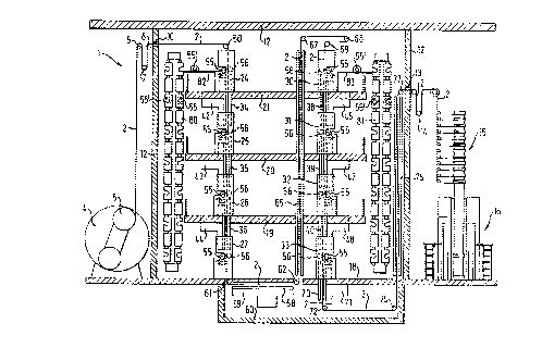
Referring firstly to Figure 1, a rotary intaglio printing
machine as shaHm therein and generally identified by reference nwr~eral
1 serves for printing in four colors on both sides of a web of paper 2
which is drawn from a paper roll 5 mounted on a roll carrier 4. Fran
the paper roll 5, the web of paper 2 extends substantially vertically
upwardly to first, second and third guide spindles 6, ? and 8 which
serve to change the direction of movgnent of the web of paper 2 into a
horizontal path in the upper part of the machine. Of the guide
spindles 6, 7 and 8, the guide spindle 7 also serves as a tensioning
roller so that, as the web of paper 2 passes from the paper roll 5 to
the first printing mechanism as indicated at 24 , the tension in the
paper can be regulated once again to the correct value.
11
'.: , . J
' . .
. :' .
.
'
r ,
' ..
~ ~ ,
,.
, p . : H .. ...
....
'
:';,
.
:
'
~- ~
'
'
i,5f'.' ,
. . .
':: :
y
. " ,,,:..
,. .y
.
.: .... .~ . .,...
' .
...~; ..,.
~
'
.
. J...
[. S
..j t.~
'
.. '. , '., ;..
'
t
:, . ' - . ,.. . . .. '.. .' ~r, ,s ; -' .,
'
,
..
. ~ S . ..
'.. ~
~ y
~f
n
: _
;..
I i
1. .
..'I t n w:
~ . ,
;W
~
f
~
~
~
'
'
.n.' ' ,
.. ,. ,.
~.:.~.
.~
~ J
:
:. ", ~.
: ''.:.' 't; .
.:. .
;~ ~.;:~
: ' ' .~
~
: .
, .
~ : w . ':.
t .
~
'
.'
,
'
:
~'
n
~:
:.~. ~'
v
~';
. ..
.. .
..; ., _
. ,
) .. ,...;:.1 .::... ,
, .
. :,r a .: i~
.. .
... .
: ,
.'
, t. '
,
y
-
.
, .,.. .,:.~.. ; '.'.:r~ , ~:...:.~ t..;~,..' .. . ~ ~ ,., . ~..,..
'.:' . . ''i ~~: '.-.'.,~.' : : ' ,.;._. '. .. ..,~ ,
1 .
.
.,
J
.
:i~l.n.
f:.~
!. ',.r~~~N
;.. . rr : '
,C i
a.. ~
-
.
...4
6~x
~
~J
,'~ ' ! '
'
W
~
~
'
'
.
.
.
. ,
..
:
;
v,? J .. ,
1 .r....
.-. ...l
. 'C
.~IS
.
: . ... ~ ;
. .. ..
,.
1 . . Y s
:
:.,7
~
'
.
.. ~
.1!.
.',., 7, r ::.
t
5.:-
. .4 ~'
. t ,
S
. f.
~
'
1
.,
'
.
.
J .,.
P . .
.... . .S/~ .
..
'.
;
J, .a
: J , , s. . I - . Z; J....:.
S,tr:.;, .l
i .. . .: 5~.. 1
..
. '.S!' . S .E. F
..
.
:7
a
..
.
4 ' ..
J
t
.,,,t [/Y t~
.:..4 '- '~ . ..
]j~y~~ a~'i f. ' .t '~ y.,:P
.,_7J . ..T', f'...' ~ ,. .t'
::J '1 t i
. hn.
.
~.;
k:SS.
'
'
'
:
... ,
,~;f..;.... . .~
-. _,
,
'.:.
.S ; v
1:;7~.....
.~ S .., , t..
_ ........r........ . ... .,r.'.::': ..,... . . .. . . _... . . ,
. ..~~!, '::~rv'..<.' : s. .
-..
2~~191~~
The horizontal portion of the web of paper 2, which follows
the guide spindles 6 , 7 and 8 , passes through a narrow entry slot ZO
into a region of the building which encloses the entire rotary
intaglio printing machine 1 in the manner of a capsule as indicated at
12. During operation of the machine, the capsule 12 is completely
se~alingly closed off, with the exception of the above-mentioned entry
slot 10 and an exit slot 13 which is disposed on the opposite side
fran the entry slot 10 and through which the fully printed web of
paper 2 leaves the capsule 12 again. The entry and exit slots 10 and
12 can be suitably closed off as required.
Downstream of the exit slot 13, the web of paper 2 with
printing on both sides thereof passes through a device 14 which again
canprises first, second and third guide spindles, for adjusting the
register condition, into a subsequent superstructure 15 which is only
indicated in the drawing. In the superstructure 15, the web of paper
is longitudinally divided and laid in superposed relationship by means
of turning bars and transversely severed by means of bladed rollers
until the web of paper is then folded in a folding apparatus 16 to
give the respective product, and collected.
Disposed in the interior of the encapsulating enclosure 12 on
the floor 18 of the building and three galleries 19, 20 and 21 to
which personnel have access on foot, are two groups each consisting of
four printing mechanisms 24, 25, 26, 27 and 30, 31, 32, 33 which are
arranged in vertically superposed relationship. Of the printing
mechanisms, the first group 24 through 27 serves to print on the first
form side of the paper with the four colors yellow, red, blue and
black, while the second group 30 through 33 serves for printing on the
back side of the paper with those colors.
Disposed between successive printing mechanisms of each of
those two groups, which are each arranged in a tower-like
configuration, are short drying sections in the foam of drying devices
,..;
~,>
",
;' ,;,. : ~. : . : . .
34, 35, 36 and 38, 39, 40 respectively. Associated with each of the
drying devices 34 through 36 and 38 through 40 are respective draw-off
hoods 42, 43, 44 and 46, 47, 48 respectively.
After the web of paper 2 has passed through a horizontal part
of its path of mavement, doNmstream of the entry slot 10, the web of
paper 2 is deflected downwardly by way of a guide spindle 50 in such a
way that it passes vertically free above into the uppermost printing
mechanism 24 of .the first group or tower forn~ed by the printing
mechanises 24, 25, 26 and 27. The web of paper 2 passes through that
entire tower of printing mechanises, that is to say all the printing
mechanisms 24 through 27 thereof and the dzying devices 34, 35 and 36
arranged therebetween, downwarclly in a vertical direction in such a
way that, in doing so, it canes into contact only with the four plate
cylinders 55 of the respective printing mechanisms and the associated
impression cylinders 56. That therefore means that the printing side
of the web of paper canes into contact only with the plate cylinders,
while the side which is not to be. printed upon in the printing
mechanisms canes into contact only with the impression cylinders 56.
The short drying devices 34 through 36 are sufficient to dry at least
the surface of the ink applied in the respectively preceding printing
mechanism 24 through 26, to such a degree that that surface is not
wiped or srrnidged or blurred in the respectively following printing
mechanise 25 through 27.
A drying device 58 with associated draw-off hood 59 is also
arranged doamstrean of the lowermost printing mechanism 27 in the
first printing mechanism tower arrangement. The drying device 58 and
the hood 59 are disposed in a trough 60 beneath the floor 18 of the
building, the interior of the trough 60 canmunicating with the
enclosed interior of the capsule 12. For reasons of saving space, the
drying device 58 is arranged horizontally so that a guide spindle 61
is disposed between the drying device 58 dnd the printing mechanism 27
disposed upstream thereof. The guide spindle 61 bears against the back
13
y ,Y ' i fI L .1.
~.
~
Pf J .
J4.' ~5 .
~ Y ,S ....J J~ ~ ,:' J . t'
... ~ .. ~ . .',~f. ., ~ 2 ~ ! ' ~..Y: f ~.h.' '
is ly .. ,
r...; ~ .s'h' J3 /..
~ ~ .
., .4 :.
Z : T
Y H ~ Jy. Jj .I I' 1:
1 ,n..,v . I .. r ~ SY 1 ' I. '
Y-.. .. ~ .. ;L', l .: ~ . r .,: t v.
.'y', < y.... t..,.r..:. ~
1. ::r ., f - 3
.. 7 , s ~ ' j..,. ~. r 5 ..,. 7,'.:i . r.~'.
t ..' i ,, ,r: v r . .
.,rt. . .,,.'. 7.r. :, r ~ -.r~:~::
,r. ~. "t.
! ' ., , ~:. ... .. r '' .i ~;.
.,,~,... t~ ., . .... . ~s. ~ ...,... ~,-. -:: ~~: . , ~. : ., ~:.~ .'
. . h G ~ '. '. ,. ,;.::. ..., ' ~ ~~~'
': s. . f(. ..,,
; 4 :. ~ ,
r x ~. i,..,. , r ,:.~ ~:''.,
..:. r r .
:i~ . t c-r..
i :.~
.:,i~~ G.:.: 1 . ,4:
.:::.. ..'~ ...~:.'4 '~ ri.
..:",: 5 ,. . ..5: ,.
'.' :.r....,. '.:..:~,:. .. :.v:.. tr. . 1.,-,'v..
:....,t. . .., ,
TI a .m 7 :, .
, ...~..h
. 1.. 4
J
.s ~ ~..~..a.-....r..h.1. c 1 . ,
., ~..~.r. Y..."
.. !to...n ..,'<:.. ,. y >r;.~' ;t
'S \ . : ~ 7 h , .:yL'
.. . :,. . ~ ....: ': '~ .....s.., .., t;.... M. ..:.. ..~..A,..,.
~..:.'.'"-, ; .:1...: . , . - -aJYn.4~..". ..:~ .,S 'w
,~-. .... . .... . ,. .... : .: .. . ,..- , , .d I'_
5...,. . -.._ ..-... .~... ... ... ., _ ..... " ,:.:........, ..
..... ,
t".,
.,
....,..
side of the web of paper 2, that is to say, the side of the web of
paper to which printing has not yet been applied. A further guide
spindle 62 is disposed downstream of the drying device 58 at the sart~e
."Level as the guide spindle 61 and also bears against the web back.
It will be seen therefore that the guide spindle 61 diverts
the web of paper from its vertical path of rrnvanent through the
printing mechanisms 24 through 27, into a horizontal path of movement
through the drying device 58. The guide spindle 62 then diverts the
web of paper 2 into a vertical path of movement again. In that path of
movement, the web of paper 2 passes upsaarrily through a long drying
device 65 which extends to a position beyond the printing mechanisms
24, 30 arranged at the uppermost gallery 21 in the building. The web
of paper 2 as it issues from the long drying device 65 is deflected
twice by way of three guide spindles 67, 68 and 69, of which the guide
spindle 68 is again displaceable for the purposes of adjusting the
register condition. The web of paper then passes from above into the
second printing mechanism tower for printing on the back of the web of
paper 2, with the printing mechanians 30 through 33 and the
respectively interposed short drying devices 38 through 40 through
which the web of paper 2 passes in the sane manner as was described
above, except that now it is the back of the paper to which printing
is applied using four inks.
The first guide spindles which cane into contact with the
front side of the paper after printing has been applied thereto are
the guide spindles 67 and 68. As, at that time, the web of paper has
passed through the long drying device 65, that contact is totally non-
critical because the inks which have been applied to the front side of
the paper in the printisig mechanisms 24 through 27 have very
substantially dried out.
Adjoining the lowermost printing mechanism 33 of the second
printing mechanism tower is a short drying device 70 which leads into
the trough 60, with a draw-off hood 71. The web of paper 2 still
14
.(:. -.~ ,. - r...!s J, r : , ~. ..! .
~
/.:5 f~:
,v... .
rr .!.
'' . /
N..:
. ..:f
Jr~l
:.
5 "'
-
~.
''
-
'
~
c
. J ,
.' 1, .. I
. :.5~.. r
. .
. rr'.~ !
A ~ !
.'.r'.' ..!.".
..s:Y.' 7
/ J'
t
/ -
r
: ~
. .. ,
.
...
..
.
p . .
"(
..7 ..
..r.
.: r ..: r:: '
'i r' - ;:
W .'rr .. . lr.,.. .,: J r.,.:~~.
~ :::4. ..,
t...J
,./. . '. .<
' .t,...... ..
t
'
~
.
~
~
.. ,
.:. ..
.. ...
..5... r.
. s.:.
r ,;..
S.. .;:1'.'. 1,.
, '.
5 J , t...,.. ;... ..~
" 30 ~
,..V '1 (
.
J:
.
h
~'
:
:.
,
,
::.5' . . .
...
. ..
.;, Y :. t::.-.
. r
f. ' : .
',. :. C ...
. J .
. \ ;.
..J.. ..,:
:..y,,. ~, , '
: : >:v ~ a . J.
t.. .,
at.
v'v', . .v'Y, . . . r . c ~ > '
! :y.S: S
n
..
~.J
:
1
~':
7!
r
.
J~'
rr
'
v
'
,
.
..
..
... .
..
. r. .. H ,. J
.i
.
".! . J... . V r.
:
.J.:.ba
l:,.
.~..~.
s. t. J. ..,.,;:: , ./ . ..JY..... :vr.~:.:v: :.r.m::.
' ~ .51.. .. ....t..., ;~.Sj4.\. t v.~ : .::, .
t.
. .
'
'
-
r
. . ..,' . , '.. . : ~. ..~,. ,
:: .". r:.,.
:.,.,:.
.5 .,.,
... ' ....: ..'. ' . - ;;.., ;..
~
f14
, ;''.
w vr'r.'
r . yr -,: , r
r . . ,.
'
,
.
.
.
.:.'. . ,,,. r
.,~: ~ . .
J!' ::~ . .
: .. :!. ~:.;
..~...,;.
.
. '
.;:y,..
:' ~'.'~'.
.~
..~.v:.::
'':
~ .
~:: - :'
:
.... . .
.. .. ,
,,
.. ~,. . ,
,.ak .. .... ..
~ .
.,.;,
! .
.
....
..
.r. ..
..: l J.: .'.
....:.:. ~~' . . ~ . .
.
.f..
....:' '.:.
-
'. .. ::.,... .,:-',r.~ , :.
.,. .
. ..
. .
f ..
'...'f.r;:.:,' ', !!' J
.f... 1.., S
P
l-
l
.::.
':
.
.,.....
,. . .;.. r..
nt ~' ~ .
... J ,
....... ' ~.i
r.r. .,:...,:: :;xr.
': '. .;:~ ..
,:.
'~ "..., .
:.. ...,::::."....
~. ....
.~:'nt
_
...
a ~:
'
'
t:, ' . :..... v.::r. ,.
':. .....,
P.. ,
..
.
,. ....,
' . .
'. "..,
..
... . .,..,-.:.: .. ..,,
. .. .:.... . .. .:,~:?:::.~~v: ::;::; :.::.......~:-...;,,..,....,.,;.~.:
.. ... ..,:... :
'::. ..... .,
s : .:.tYw .,.
...Ii:.:
':4't:':r.
....J' A!
'...t:' -
5.,. ,.
: .
:
t ~
:
.
S
'
. .. s
. . ,;t.: . .. ;. ,.
:. . . ;
.. .
- ' .
- .J
r,:.S" ;. t:
...SP.'.,.t
. ,..:.. ;,.
hi:. Y. ..,:.
.,;.
;~. :...~../..
.~J..... ~ t
.~
'Js
':J
'
,.,.::.. . .
, t.,
- .... .. .. ".. .
.. "...... ' ...(','. t
.:..Y'
:4.,.. ..-..
. .::5.. p
. ... ~~ r. ...Sm...... ......... ..... ... . . .
..... - 1i.'?:- .....,..,.. .. . ...v.. ...... .
, .. . '
2~.0~~.~~
passes through the drying device 70 in a vertical direction because
the downstream-disposed guide spindle 72 which serves to deflect the
web of paper 2 into a horizontal direction again canes into contact
with the back side of the paper to which printing is applied in the
second tower arrangement of printing mechanisms. After passing around
the guide spindle 72 and travelling along a short horizontal path of
mwetnent in the trough 60, the web of paper 2 is again deflected by
means of a guide spindle 74 into a vertical path of movanent in which
it passes vertically upwardly through a further long drying device 75
which extends approximately as far as the level of the uppern~ost
gallery floor 21. At that location is a further guide spindle 77, by
means of which the web of paper 2 is again deflected into a horizontal
path of movement in order then to leave the capsule 12 through the
exit slot 13.
L5 It will be seen fran the foregoing description that the whole
of the rotary intaglio printing machine 1 which is suitable for four-
color printing on both sides of a web of paper 2 requires only nine
guide spindles between the entry slot 10 and the exit slot 13, which
approximately corresponds to the nunber of guide spindles us~i in a
single printing mechanism in a previously conventional n~taxy intaglio
printing machine. The total length of paper which is to be found at
any time in the machine according to the invention, that is to say
within the encapsulating enclosure 12, is approximately four times the
height of the overall arrangement plus its length, that is to say the
distance between the entry slot 10 and the exit slot 13. If account is
taken of the fact that a conventional irotary intaglio printing machine
with eight printing mechanisms requixes approximately twice the length
and the web of paper in each conventional printing mechanism with
associated drying device must twice pass through half the height of
the installation shown in Figure l,it will be seen that the
arrangement of the machine in accordance with the invention halves the
length of paper disposed in the installation at any time.
'
~
$r i' rr ', . .
'v ; v.$;
r
' r r
;..v . ~ t.'..'
.t:~.; r
r~~r : r;
'
,
r
v:
r
. . Trr . ~ .: ~
.
; y ~ :S. ,
4: r
~
~ '
~
r C ~
,
..:' ~ ~
::.. k , ,~~;!!~r'rrr . ~~: rr
r..';
: ,
-...;
?
'~;
v v ;;;
!;
'':
. .. ,
' .
,
.. ..
,.: .
.
.
,
'
S ' 41
.. .. . ., ,, . .
~ .
; , ,,, .:. ~'',, r , . r '
2~~916~
Looking now additionally at Figures 1 and 2, it will be seen
that the printing mechanisms are 'open' towards one longitudinal side
so that the plate cylinders can be exchanged by way of that side. In
Figure 1, the 'open' side of the printing mechanisms 24 through 27 of
the first tower arrangement is towards the left while the open side of
the printing mechanisms 3G through 33 is towards the right.
Accordingly, disposed to the left of the tower arrangement fob by
the printing mechanisms 24 through 27 and to the right of the tower
arrangement formed by the printing mechanisms 30 through 33 are
respective elevators 80 and 81 respectively which are here in the form
of a paternoster arrangement. Sy means of the elevators 80 and 81, any
plate cylinders 55 which are no longer required can be simultaneously
rgnaved fran all printing mechanisms of a tower arrangement, and the
fresh plate cylinders can be simultaneously supplied to the tower
arrangement in a subsequent working operation. That is symbolically
indicated in Figure 1 in respect of the uppermost printing mechanisms
24 and 30 of the two tower arrang~nents, by means of a respective
plate cylinder 55' which is on a conveyor device 82, 83 respectively
that leads from the elevator 80 or 81 to the respective printing
mechanism 24 or 30. At the level of the upper gallery 21, Figure 1
shows two plate cylinders 55' in both elevators 80 and 81, in order to
show the way in which they are carried in the elements of the
paternoster arrangement.
Figure 2 again shows on a greatly enlarged scale the uppermost
printing mechanism 24 of the first tower arrangement for printing on
the first or front side of the web of paper 2. Figure 2 very clearly
shows the way in which 'the plate cylinder 55 dips into an ink trough
or fountain 85 and on its 'exit side is freed of the excess ink by
means of a doctor blade 86. The doctor blade is in operation arranged
at such a level that the generatrix along which the doctor blade is in
contact with the plate cylinder 55 during a printing operation is no
higher than the axis of rotation 57 of the plate cylinder and
16
wr...,.:
..
";.::
i.
21~~16~
preferably, as illustrated, it is lower than the axis of rotation 57.
By virtue of that arrangement, the doctor blade 86 has to be lowered
only slightly or not at all when the plate cylinder is to be replaced.
Referring now to Figure 3, in order to minimize the height by
which the plate cylinder 55 has to be raised when ring same fran
its printing mechanism and lowered when installing it again, the shaft
journals 87 thereof are preferably mounted in the manner shown in
Figure 3 in a backrest-like or cradle-type mounting 90 which has for
exanple three mounting rollers 88.
An important consideration in regard to the entire arrangement
of the machine according to the invention ~s on the one hand that the
printing mechanisms for printing on one side of the web of paper are
arranged aligned with each other in such a way that the web of paper 2
can pass fran one plate cylinder-impression cylinder pair to the next
without that involving a substantial change in the direction of
movement of the web of paper. In that way, the guidance effect
provided by the plate cylinders and the associated impression
cylinders is fully sufficient for the web of paper to be guided at
least through all the printing mechani~ns which are required for
printing on one side of the web of paper. That design configuration
which thus results in a considerable reduction in the nwrnber of guide
spindles required can be employed not only with the tower-like
arrangement shc~m in the illustrated embodiment, but also when the
printing mechanisms are arranged horizontally one behind the other. It
is also possible without departing fran the scope of the invention to
conceive of rotary intaglio printing machines in which the eight
printing mechanisms required for four-color printing on both sides of
the web of paper are arranged in four towers, each of which comprises
two printing mechanisms in superposed relationship. The invention is
also not restricted to four-color printing on both sides, but can be
used whenever printing is to be applied to a web of paper by means of
two or more printing mechanisms.
17
:i
2~.fl~lfi~
On the other hand, another aspect of considerable significance
is that the elimination of guide spindles which in previous machines
were arranged in the immediate vicinity of the respective printing
nips of the printing mechanisms, the lower positioning of the doctor
arrangement, and the use of the cradle-type bearings mean that removal
and installation of the plate cylinders, transversely to the
lengthwise direction thereof, is simplified to such a degree that that
operation can be substantially automated.
It will be noted that the elevators 80, 81 can also be
arranged outside the encapsulating enclosure 12. In that case, disposed
at the level of each printing mechanism outside the capsule 12 is a
preparation apparatus which, during a printing operation, is separated
fran the interior of the capsule 12 by a suitable closure device which
for exanple is in the form of a venetian or slat-type blind device.
That affords the advantage that any plate cylinders which are required
for the next printing operation in a printing mechanism tower
arrang~rient can be moved into position with a simple lift, while the
preceding printing operation is still taking place. When that preceding
printing operation is concluded, the closure devices are opened, the
plate cylinders which were previously being used are rerraved fran the
printing mechanisms and the capsule 12, and put into storage in the
preparation apparatus. After that, the plate cylinders required for
the next printing operation can be moved into the interior of the
capsule 12 and fitted into the respective printing mechanisms.
Thereupon the closure devices are closed and the next printing ;
operation can be carmenced. After that, there is again sufficient time
for the plate cylinders which were previously in use and which have
been deposited on the preparation apparatus to be individually lowered
by means of the lift to the ground and there transported away.
The final drying device 75 may also be disposed outside the ,
capsule 12.
18
y 'f r' J ,.f
.JJ:.h " .. J
i~'J: L. " , .~ l.1'i.
7 , ._ '. S..! . ...-.i .:. t . -.1. .
J ' ..1 L
J-
f
~
~
~
,
~, . ,',; ,;,:J 1I ..
'. . ..J.c. J
.. .. .7 "! . .l.J.i' ,
~ 'J
' .
I i,n.' r.~
Y '-.J . ' t . .. I,:;J S'iJ . . .1JV.: ..f ',
...L....
:.
~ ..1.... ..J.;:
:
Y
I
..
J. S . .
. .
. f ' u
L.~ L ~~/ ~AL .SY:, 1J. .1 n. 7 .
.Y' ~ .~ G .. .
. ~ ..4..... :LT./ ..,:~. (.:.. SL..
~ ;~.. . ,: ~ . I.. .../., V -L~..'~.
. .ms s' .. 12
.1.
r
J
\
~
'
'
~
~~
'
'
.L . ,
>~. i s .
\~ i . . .
.. J; ".kLJ ' . ...., ,
.. .! !., ,.,
~ ,...
!.i'
.J..
IL
.. .J
,
, v,: . ,.
Y:: .!5
,...;~:
.;rr,l ..v. -.
. fL.... , ~. ( ; :,r,. . . t~ : ..J. .,.,\, ,
..
t
~
~!":
v~~~~
i
~
~
" ' J i
L.,. , ...L J;.,, ..
,~.L ...r:
" ~.~ ..
'.:J , ,.
..'.
.
..
.
,ri.,.. 'w:':
, J... ..~x~.,.. .w..
i'' ,X.::." t.'.,_ I,'\~,. nrw'4' ,L
:v: ...i.
r
J
r'
~
~
F
~
.,... , L ,
,.J ..
~ ..
:7-..
, .,L.'i.. : J''..;;,. ,
i .,l ,..r... .
f: .i :- ..
..1,,..< s~ .
' r '.y;.
.
~
. ,
r .:(J\ ~ 1 ; . ; t ,! . . i''
: '4'~ ~f:~ti' r :: ;i'~..,.. r '
~~ '
~
~
. . . ,
r .. 4 '.,
, . r, p . ; . L
.( J
~...
.
~
.
~.i,
', t..
.
;
i
~
v J
i .
: 5
~' =
' :'
~
1~'!~
v
~'I
~
~
_ , .t
: .
~ ./ . .f
i ,;.;,. ~t~.l
Y :,
~f '
. . Pr
,...~~..a. ..f."',~ rt.;.n.,,,r r
~f ~
i ,; 5..;. w:rr'
K
s
!L
~
t -
yL
J. . _
' 1
~ ~
~' >, ~ :.v': S
tS JYr. . -p.. ~~ p ,
i.~~
:4.:"f .i
I.v
.
h
~
~
.. .
. fit. .
(, S t; ..
.~ :
a:. ,., c.i.,....LYW ..
.; ~,"~ " ( . . a . ,
.t. .: rr~. ...
:..:y f -
' ,~E' (. f ~J J
L
~
~
.
~i~' .
1P ..C..
f .';-. f
'.~fT Y -..'
r. 'Y. :
w ~ w ' t. ,. L.:,.. :
il.:. 1't .-., ! '.fJ,~ ... /"'
..~W 1.T ... P.. ... .:J'T ... 1,.: t .~ f.. '.
L x '. y.:
:
~:
"
4~
'
. "
t..r :.
, .
s .;
.
. J
.r....~, ~.. ,.(
r~.:t. ,.r:,
5 ;.::. .:-'J.-i J.;, .,
r ~ ., ,
.. t t > : f .. .,c
. >t lc.:
f f ,.. 3 r' > : -.
~.Yy :' i ..,. f :...' S
,, :,. . t c. : : ,. ., ,
t
! : , .r .,~
s:
F1,: r..;.:....
~
r
'
'
-
f. .., .
s:
a,;
S. J. 5 ...:;
. '
., ....." ': S j,..., !.Y.,
. . .>.....
y,
... ,..... x"
.. . J, .. 'li .
1 , ~ ., l J:-': J -.
. .. . ....... ._z... . ._.in.Ye . '4.'.!'. ,...._
.,...... W ... . , v ..... 1 ,'.., ,.
2~.0~~.6~
As an alternative to the horizontal arrangement shown in
Figure 1, the drying device 58 arranged beneath the first tower
arrangement for printing on the first or front side of the web of
paper can also be designed and arranged vertically in the same manner
as shown in respect of the drying device 70 at the bottom of the
second printing mechanism tower arrangement. In that case, the guide
spindle 61 is positioned downstream of the drying device 58 as the web
of paper 2 passes in a vertical direction dawnwardly through the
vertically arranged drying device 58, still without being guided
thereby, until it then reaches .the guide spindle downstream of the
drying device 58 for diverting it into a horizontal direction in order
for it subsequently to pass upwardly through the long drying device
65.
It will be appreciated that the above-described printing
machine and the printing process carried out therein have been set
forth solely by way of example and illustration of the principles of
the present invention and that various modifications and alterations
may be made therein without thereby departing from the spirit and
scope of the invention.
19