Language selection

Search

Patent 2109174 Summary

Third-party information liability

Some of the information on this Web page has been provided by external sources. The Government of Canada is not responsible for the accuracy, reliability or currency of the information supplied by external sources. Users wishing to rely upon this information should consult directly with the source of the information. Content provided by external sources is not subject to official languages, privacy and accessibility requirements.

Claims and Abstract availability

Any discrepancies in the text and image of the Claims and Abstract are due to differing posting times. Text of the Claims and Abstract are posted:

  • At the time the application is open to public inspection;
  • At the time of issue of the patent (grant).
(12) Patent Application: (11) CA 2109174
(54) English Title: TUBE SWITCH
(54) French Title: COMMUTATEUR A MERCURE
Status: Deemed Abandoned and Beyond the Period of Reinstatement - Pending Response to Notice of Disregarded Communication
Bibliographic Data
(51) International Patent Classification (IPC):
  • B65G 53/56 (2006.01)
  • F16K 11/06 (2006.01)
(72) Inventors :
  • BRANDAUER, OTTO (Germany)
  • GROTH, GERHARD (Germany)
(73) Owners :
  • FILTERWERK MANN & HUMMEL GMBH
(71) Applicants :
  • FILTERWERK MANN & HUMMEL GMBH (Germany)
(74) Agent: BORDEN LADNER GERVAIS LLP
(74) Associate agent:
(45) Issued:
(22) Filed Date: 1993-10-25
(41) Open to Public Inspection: 1994-04-27
Examination requested: 1997-07-18
Availability of licence: N/A
Dedicated to the Public: N/A
(25) Language of filing: English

Patent Cooperation Treaty (PCT): No

(30) Application Priority Data:
Application No. Country/Territory Date
P 42 35 860.4 (Germany) 1992-10-26

Abstracts

English Abstract


ABSTRACT OF THE DISCLOSURE
A multi-way distributor having at least two mutually
parallel and displaceable disks provided with at least two
through-holes or connection pieces. At least two flexible tubes
are fastened to at least two of these displaceable disks, and by
the relative movements of the disks with respect to one another,
different connections can be achieved which the distribution of
the material flows takes place.
-9-


Claims

Note: Claims are shown in the official language in which they were submitted.

THE EMBODIMENTS OF THE INVENTION IN WHICH AN EXCLUSIVE
PROPERTY OR PRIVILEGE IS CLAIMED ARE DEFINED AS FOLLOWS:
1. An arrangement for distribution of material flows in
tube systems, comprising:
at least two mutually parallel and movable disks which have
at least two through-holes;
at least two flexible tubes fastened to at least two of
these movable disks;
wherein, by relative movements of the disks with respect to
one another, different connections are achievable by which the
material flows are distributed.
2. An arrangement according to Claim 1, further comprising
adjusting elements coupled to the movable disks, the adjusting
elements being at least one of pneumatic and electric.
3. An arrangement according to Claim 1, further comprising
a driving element coupled to the movable disks, wherein the
driving element is a motor operator.
4. An arrangement according to Claim 1, further comprising
at least one approximation initiator coupled to each movable
disk, the approximation initiators controlling coordinates of the
movable disks.
5. An arrangement according to Claim 1, further comprising
connection pieces coupled between the through-holes and the
-6-

flexible tubes, wherein the connection pieces for the flexible
tubes are movably disposed on the movable disks.
6. An arrangement according to Claim 5, wherein the
connection pieces for the flexible tubes on the movable disks
have a perforated area.
7. An arrangement according to Claim 6, further comprising
a movable sealing disk for the evacuation by suction, the movable
sealing disk being mounted during a distributing operation over
the perforated area of the connection piece.
8. An arrangement according to Claim 7, wherein the sealing
disk for the evacuation by suction must be moved away from the
perforated area of the connection piece to implement a type
change.
9. An arrangement according to Claim 1, wherein the movable
disks are rotatable about a central axis.
10. An arrangement according to Claim 1, wherein the
movable disks are guided in one-dimensional curves which are
mutually perpendicular.
11. An arrangement according to Claim 1, wherein the
movable disks are guided in two-dimeneional movable curves.
-7-

12. An arrangement according to Claim 11, further
comprising a planetary gear system coupled to the rotary disks.
13. An arrangement according to Claim 1, wherein the
arrangement is a tube switch.
-8-

Description

Note: Descriptions are shown in the official language in which they were submitted.


2109174
A TVBE SWITCH :;
Backaround of tho Invention
The present invention relates to a tube switch for the
distribution of material flows in tube systems.
Distributors of this type are known; for example, from the
Journal Kunststoffe (Plastics), 80th Year, Pages 772 to 775, or
from German Utility Model 18 77 476.
Several distributors of the type according to German Utility
Model 18 77 476 might be connected in order to obtain a certain
number of distribution possibilities. However, this arrangement
would be complicated to control, and the solution would require -~
a lot of space and would become correspondingly expensive. In
the case of distributors of this type, particularly the long tube
paths, which have to be evacuated in the case of a change of
types, are also disadvantageous.
Summary of the Inv ntion
It is therefore an object of the invention to improve a
distributor of the initially mentioned type such that a flexible
distributor is provided which is easy to operate, small in size,
easy to clean, and low in cost.

2109174
This and other objects are achieved according to the pre~ent
invention in that at least two disks are provided which are
parallel and displaceable with respect to one another and are
provided with at least two through-holes and/or connection
S pieces, in which case at least two flexible tubes are fastened
to at least two of these displaceable disks. By relative
displacements of the disks with respect to one another, different
connections are achievable, by means of which the distribution
of the material flows takes place.
Because of the parallel disks, which are maximally spaced
by a stationary housing wall between the displaceable disks, an
extremely low dead volume that can be evacuated with low
expenditures in time and energy will occur in the case of a
change of articles. By means of the appropriate selection of
disks and flexible tubes, an extremely flexible and efficient
distributor system is obtained which can establish within a short
period of time appropriate connections between, for example, a
silo of material and a processing machine.
Other objects, advantages and novel features of the present
invention will become apparent from the following detailed
description of the invention when considered in conjunction with
the accompanying drawings.
Brief Description of the Drawina~
... .
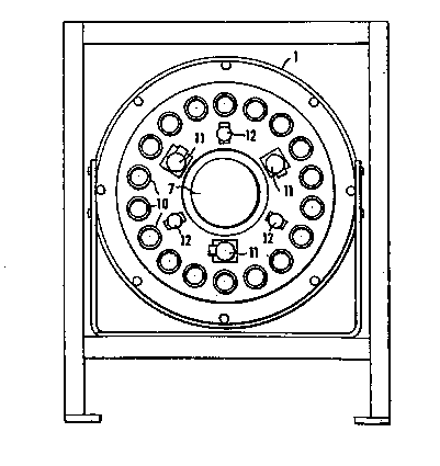
Figure 1 is a frontal view of a distributor constructed in
accordance with an embodiment of the present invention;
Figure 2 is a sectional view of the embodiment illustrated ~-
in Figure 1 during a conveyance;
-2-

2109174
Figure 3 i8 a sectional view of the embodiment illustrated
in Figure 1 during the evacuation by suction for the purpose of
a change of articles;
Figure 4 is a lateral view of the embodiment of Fi.gure 1;
Figures 5a and 5b are schematic representations of the
connections between machines and silos;
Figure 6 is a plan sectional view of another embodiment of
the present invention;
Figure 7 is an end view of the embodiment of Figure 6; and
Figure 8 is a schematic sectional plan view of another
embodiment of the present invention.
Detailed DescriDtion of Preferred EmbodimQnts:
Figure 1 illustrates a multi-way distributor. The
illustrated embodiment represents eighteen silo connections and
eighteen machine connections, although other numbers of
connections can be provided in different embodiments. As seen
in Figure 2, the rotary disks 2 and 3 are disposed in the housing
1 and are axially fixed by the sealing disks 9. The drives 7 and
8 are fastened to the rotary disks 2 and 3 and drive these by way
of the housing 1. The motors 17a, 17b coupled to the drives 7
and 8 are illustrated schematically in Figure 2 only and are
constructed to be self-locking. Schematically illustrated
planetary gear systems l9a, l9b are coupled between the motors
17a, 17b and the drives 7, 8. An exact rotating position is
adjusted electronically or pneumatically in a known manner by
approximation initiators 14. The hose couplings 5 and 6 are
fastened in the disks 2 and 3 by rotatable connecting pieces 10
-3-

210917~
ln order to counteract torsional forces during the rotating of
the disks 2 and 3. The connecting pieces 10 have bores 13. The
sealing disk 4 for the evacuation by suction is pressed axially
against the rotary disk 2 by lifting cylinders 11 and is held by
pressure spring guides 12. The sealing disk 4 for the evacuation
by suction can be axially displaced by the lifting cylinders 11.
Starting from a zero point, the rotary disks 2 and 3 can be
rotated in both directions, for example, by 90o, in order to
avoid a complete rotation in this manner and therefore
unnecessary torsional stress in the flexible tubes. In the
normal position, all hose connections from the silo to the
machine are open in a certain combination. In this case, for
example, a conveyance by suction may take place from silo S 1 to
machine M 1 and from silo S 9 to machine M 9 (Figure 5A). After
the end of a conveyance, for example, from silo S 1 to machine
M 1, the lifting cylinders 11 are activated and the sealing disk
4 for the evacuation by suction is axially displaced, whereby the
bores 13 for the evacuation by suction are opened up. By means
of this operation, the material flow from the silo is interrupted
and the line between the suction evacuation bore 13 and the
machine i8 evacuated by suction. If, for example, a material
conveyance pairing of silo S 1 to machine M 9 is desired (Figure
5b), rotary disk 2 is displaced by 90o clockwise and rotary disk
3 is displaced by 90o counterclockwise. Because of the small
dead space caused by the housing 1 and the evacuating of residual
material carried out by means of bores and the sealing disk 4 for
the evacuation by suction, virtually no mixing of materials can
occur.

~109~74
Figures 1 through 4 show an embodiment of the invention in
which the material stream couplings across the movable plates or
disks are switched through a change of the relative angular
positions of the plates in a polar coordinate system. By
contrast, an embodiment illustrated in Figures 6 and 7 controls
or regulates the distribution of the material streams by guiding
the movable plates or disks 2', 3' in two dimensions. Either one
or both of the plates 2', 3' can be moved in the x and y
direction via the drives 7~.
Figure 8 schematically illustrates another embodiment in
which the plates 2'', 3'' are moveable relative to one another
in one dimension only.
Although the invention has been described and illustrated
in detail, it is to be clearly understood that the same is by way
of illustration and example, and is not to be taken by way of
limitation. The spirit and scope of the present invention are
to be limited only by the terms of the appended claims.

Representative Drawing
A single figure which represents the drawing illustrating the invention.
Administrative Status

2024-08-01:As part of the Next Generation Patents (NGP) transition, the Canadian Patents Database (CPD) now contains a more detailed Event History, which replicates the Event Log of our new back-office solution.

Please note that "Inactive:" events refers to events no longer in use in our new back-office solution.

For a clearer understanding of the status of the application/patent presented on this page, the site Disclaimer , as well as the definitions for Patent , Event History , Maintenance Fee  and Payment History  should be consulted.

Event History

Description Date
Application Not Reinstated by Deadline 2001-10-25
Time Limit for Reversal Expired 2001-10-25
Deemed Abandoned - Failure to Respond to Maintenance Fee Notice 2000-10-25
Inactive: Approved for allowance (AFA) 2000-09-27
Inactive: IPC assigned 1999-07-14
Inactive: First IPC assigned 1999-07-14
Inactive: IPC removed 1999-07-14
Inactive: IPC assigned 1999-07-14
Amendment Received - Voluntary Amendment 1997-10-08
Letter Sent 1997-08-29
Inactive: Application prosecuted on TS as of Log entry date 1997-08-28
Inactive: Status info is complete as of Log entry date 1997-08-28
Request for Examination Requirements Determined Compliant 1997-07-18
All Requirements for Examination Determined Compliant 1997-07-18
Application Published (Open to Public Inspection) 1994-04-27

Abandonment History

Abandonment Date Reason Reinstatement Date
2000-10-25

Maintenance Fee

The last payment was received on 1999-09-15

Note : If the full payment has not been received on or before the date indicated, a further fee may be required which may be one of the following

  • the reinstatement fee;
  • the late payment fee; or
  • additional fee to reverse deemed expiry.

Patent fees are adjusted on the 1st of January every year. The amounts above are the current amounts if received by December 31 of the current year.
Please refer to the CIPO Patent Fees web page to see all current fee amounts.

Fee History

Fee Type Anniversary Year Due Date Paid Date
Request for examination - standard 1997-07-18
MF (application, 4th anniv.) - standard 04 1997-10-27 1997-09-22
MF (application, 5th anniv.) - standard 05 1998-10-26 1998-09-21
MF (application, 6th anniv.) - standard 06 1999-10-25 1999-09-15
Owners on Record

Note: Records showing the ownership history in alphabetical order.

Current Owners on Record
FILTERWERK MANN & HUMMEL GMBH
Past Owners on Record
GERHARD GROTH
OTTO BRANDAUER
Past Owners that do not appear in the "Owners on Record" listing will appear in other documentation within the application.
Documents

To view selected files, please enter reCAPTCHA code :


To view images, click a link in the Document Description column. To download the documents, select one or more checkboxes in the first column and then click the "Download Selected in PDF format (Zip Archive)" or the "Download Selected as Single PDF" button.

List of published and non-published patent-specific documents on the CPD .

If you have any difficulty accessing content, you can call the Client Service Centre at 1-866-997-1936 or send them an e-mail at CIPO Client Service Centre.


Document
Description 
Date
(yyyy-mm-dd) 
Number of pages   Size of Image (KB) 
Description 1995-06-08 5 305
Abstract 1995-06-08 1 15
Description 1997-10-07 5 184
Claims 1995-06-08 3 71
Drawings 1995-06-08 6 121
Representative drawing 1998-08-23 1 16
Acknowledgement of Request for Examination 1997-08-28 1 178
Courtesy - Abandonment Letter (Maintenance Fee) 2000-11-21 1 183
Fees 1996-09-17 1 44
Fees 1995-09-20 1 50