Note: Descriptions are shown in the official language in which they were submitted.
PCT/US92/0~1
~2~
ACCUMULATOR HEAD FOR EXTRUSION BLOW MOLDING MACHINE
TECHNICAL FIELD
The present invention relates to extrusion blow
molding machines for providing blow molded containers and
5 other hollow articles. More particularly, the invention
relates to an accumulator head for an extrusion blow
molding machine wherein plasticated material is received in
a tubular accumulator and is then extruded through an
outlet die to provide a tubular parison from which the
10 bottle or other hollow article is thereafter formed by blow
molding.
BACKGROUND ART
Containers and other hollow articles are freq~ently
formed by blow molding, which involves providing a tube of
15 heated and softened plastics material about which a two-
piece mold is enclosed, after which air or other gasses are
introduced under pressure into the tube to expand it
against the walls of the mold to thereby form the desired
hollow article. Such blow molding machines can be of
20 various types, the most common of which are extrusion-blow
molding machines and injection-blow molding machines.
In extrusion-blow molding machines, plastics material
is heated and softened in an extruder and is conveyed into
a die head from which a tubular parison is extruded. The
25 parison can either be continuous, whereby a plurality of
molds are sequentially enclosed about successive, axially
spaced portions of the parison, or individual parisons can
be intermittently extruded and subsequently blown. In the
latter instance, the die head includes a chamber, usually
30 called an accumulator, in which the extruded material is
accumulated to provide a predetermined volume of material,
after which the accumulated volume of material is extruded
',~
PCT/US92/0~81
2 ~
through an extrusion die at the outlet of the accumulator
to form a parison having the desired length, diameter, and
wall thic~ness distribution.
Most often, the extrusion head is so oriented as to
cause the parison to be extruded downwardly in a
substantially vertical direction. Additionally, the heated
and softened plastics material is normally provided by a
screw-type extruder that is disposed horizontally, and the
output from the extruder is discharged horizontally into
the e~trusion head. Because the extrusion head includes a
central cylindrical mandrel to control the flow of material
through the accumulator outlet or extrusion die, the
horizontally entering material must separate and flow
around the cylindrical mandrel and then recombine to permit
the material to flow in an annular flow path along the
mandrel and toward the extrusion die outlet. Oftentimes,
the material does not intimately join together as it flows
around the cylindrical mandrel to recombine, thereby
resulting in the formation of a joint or flow line that can
result in a longitudinal surface line or ridge on the
extruded parison. Such a line or ridge on the parison can
affect the appearance or quality of the blown article.
The present invention overcomes or at least lessens the
shortcomings described above.
The present invention provides an accumulator head in which
incoming extruded material is divided into a plurality of streams
that are then recombined to provide a uniform annular flow of
plasticated material to provide a circumferentially uniform extruded
parison.
DISCLOSURE OF INVENTION
Briefly stated, in accordance with one aspect of the
present invention, an accumulator head is provided for an
extrusion-blow molding machine for providing a uniform
extruded parison. The accumulator head includes a tubular
outer barrel having a barrel wall that includes a
, ~
WO93/01~0 PCT/US92/0~81
3 ~ 2-;i
cylindrical barrel inner surface, and a material inlet and
a material outlet.
An annular inner sleeve is slidably received within
the outer barrel for movement along the barrel inner
5 surface. The inner sleeve includes an external, material-
receiving slot adapted to communicate with the material
inlet of the outer barrel. At least two radially inwardly
directed flow apertures extend from the material-receiving
slot to the inner surface of the inner sleeve.
A tubular inner body member is slidably received
within the inner sleeve for movement along the inner sleeve
inner surface, the inner body member including a plurality
of helical channels, each channel being in communication
with the respective one of the flow apertures in the inner
15 sleeve. The channels extend along the outer surface of the
inner body member.
An actuator is provided for simultaneously moving the
inner sleeve and the inner body member toward the material
outlet to extrude material therethrough and thereby form a
20 parison.
BRI~F DESCRIPTION OF DRAWINGS
Figure 1 is a side elevational view of an extrusion-
blow molding machine having an accumulator head in
accordance with the present invention.
Figure 2 is a fragmentary side elevational view,
partially in section, showing the structure of an
accunulator head in accordance with the present invention
wi~h an accumulator sleeve and inner body member shown in
a retracted position.
Figure 3 is a view similar to Figure 2 showing the
accumulator inner sleeve and inner body in an extended
position after accumulated material has been expelled from
the Accumulator through the parison die outlet.
Figure 4 is a front view of the accumulator inner
35 sleeve looking in the direction of movement of the incoming
WO93/01~0 PCT/US92/0~1
210'~2~ 4
plasticated material that enters the sleeve from the
extruder.
Figure 5 is a side view of the accumulator inner
sleeve, rotated 90~ about its own axis relative to the
5 position shown in Figure 4.
Figure 6 is a side view of the accumulator inner body
member.
Figure 7 is another side view of the inner body
member, rotated 90~ about its own axis relative to the
10 position shown in Figure 6.
BEST MODE FOR CARRYING OUT THE INVENTION
Referring now to the drawings, and particularly to
Figure
1 thereof, there is shown an extrusion-blow molding machine
-15 10 including a generally rectangular base or frame 12.
Positioned on the top horizontal frame member 14 is an
extruder 16 in the form of a tubular barrel 18 having a
rotatable plastication screw (not shown) that includes one
or more helical flights for conveying and for softening
20 solid plastics material to provide a viscous, flowable mass
for extrusion.
The plastic material is introduced into a feed hopper
that communicates with an opening (not shown) in
extruder barrel 18. The screw is rotated by an hydraulic
25 motor 22 that receives pressurized hydraulic fluid from an
hydraulic pump 24 driven by an electric motor 26.
Hydraulic motor 22, hydraulic pump 24, and electric motor
26 are suitably supported on frame 12. Additionally, an
electrical system cabinet 28 is provided for housing
30 switches, relays, and the like used for controlling the
operation of the machine.
The outlet 30 of the horizontally disposed extruder
barrel 18 is connected with a material inlet 32 on a
substantially vertically disposed accumulator head 34,
35 which receives the plasticated material from extruder 16.
Positioned below accumulator head 34 is a blow mold 36 that
WO93/01~0 PCT/US92/0~81
210322.~
can be in the usual form known to those skilled in the art
and in the form of two horizontally opposed mold portions
38, 40, each of which has opposed, recessed areas that
define a mold cavity (not shown) when the molds are brought
5 together. The mold cavity conforms in shape with the
desired external surface conformation of the blow molded
article. A slidable cover or gate 42 is provided in front
of blow mold 36.
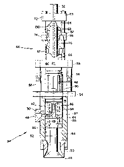
Accumulator head 34 is shown in greater detail in
10 Figures 2 and 3. As there shown, an accumulator outer
barrel 44 of tubular form is provided and is oriented with
its axis extending substantially vertically. A transverse
material inlet aperture 46 is provided through the wall of
outer barrel 44 to provide communication between the
15 interior of barrel 44 and outlet 30 of extruder 16.
Accumulator outer barrel 44 includes a material outlet
in the form of die outlet 48 through which a tubular
parison (not shown) is extruded. Die outlet 48 is defined
by a die outer ring 50 that is secured to an end of
20 accumulator outer barrel 44, and by an inner mandrel 52
that has an outer cylindrical surface spaced from the inner
surface of die outer ring 50 to define a parison outlet of
substantially annular form to provide a tubular parison.
The upper end of accumulator outer barrel 44 includes
25 a flange 54 that carries a plurality of axially extending
support rods 56 that extend upwardly from flange 54 and
connect with a lower end cap 58 of an hydraulic cylinder
60. A divider 62 is positioned within cylinder 60 to
divide the cylinder into two separate and distinct, axially
30 aligned cylinders, an upper, programming cylinder 64, and
a lower, purge cylinder 66.
PLG~Lamming cylinder 64 contains a programming piston
68 that is secured to mandrel 52 and is capable of movement
in a vertical direction within programming cylinder 64 in
35 response to hydraulic pressure applied to one of the
transverse faces of piston 68 to carry mandrel 52
vertically up or down to vary the size of the annular
WO93/01~0 PCT/US92/0~81
210~2S 6
opening at parison die outlet 48. For that purpose,
programming cylinder 64 includes a cylinder upper end cap
70 within which a programming cylinder downstroke inlet 72
is provided to communicate with the uppermost surface of
5 programming piston 68. A programming cylinder upstroke
inlet 74 is provided in cylinder divider 62 for providing
communication with the lowermost surface of programming
piston 68.
Purge cylinder 66 contains a purge piston 76 that is
10 capable of sliding movement within cylinder 66 in a
vertical direction for expelling material from accumulator
head 34, as will be hereinafter described in greater
detail. A purge cylinder head end inlet 78 in cylinder
divider 62 provides communication with the upper interior
15 end of purge cylinder 66. A purge cylinder rod end inlet
80 is provided in cylinder lower end cap 58. As shown,
purge piston 76 includes an annular rod member 82 that
surrounds and is slidably carried on mandrel 52.
Accumulator outer barrel 44 has an inner cylindrical
20 surface 84 that slidably receives an annular accumulator
inner sleeve member 86. Positioned within inner sleeve
member 86 is an inner body member 88, also of annular
configuration. Inner body member 88 includes a cylindrical
inner surface 90 that surrounds and engages the outer
25 surface of mandrel 52 to permit relative sliding movement
inner body member 88 along the outer surface of mandrel 52.
The outer surface 92 of inner body member 88 includes a
pair of helically disposed channels 94 for conveying
plasticated material, as will be hereinafter explained.
Accumulator inner sleeve member 86 and accumulator
inner body member 88 are each secured to the lower end of
an annular connector member 96 that extends through flange
54 and is connected with annular rod member 82. Connector
member 96 includes a plurality of external, longitudinally-
35 extending pressure relief grooves 98 to prevent the build-
up of excessive pressure within accumulator 34.
WO93/0lW0 PCT/US92/0~81
7 210922~i
Referring now to Figures 4 and 5, accumulator inner
sleeve 86 is of generally annular configuration and
includes a cylindrical inner bore 100 that extends from an
upper end wall 102 to a point 104 inwardly of a lower end
5 106, and that then flares downwardly and outwardly to
define a diverging wall 108. Outer surface 110 of inner
sleeve member 86 includes a longitll~inAlly extending
peripheral flow slot 112 that extends along approximately
one-half the axial length of inner sleeve member 86. The
10 upper end 114 of slot 112 is closed, and the lower end 116
communicates with a pair of side channels 118, 120, each of
which curves around from lower end 116 and upwardly along
about one-quarter of the outer periphery 110 of sleeve
member 86 to terminate in respective radially inwardly
15 extending flow apertures 122, 124 that pass through the
sidewall of sleeve 86 to provide communication with lnner
bore 100. Apertures 122, 124 are in opposed relationship,
and are at substantially the same axial height along the
axis of sleeve member 86 as slot upper end 114.
Inner body member 88 is shown in greater detail in
Figures 6 and 7 and includes an upper flange 126 that is
adapted to be connected with annular connector member 96.
Body member 88 is of generally tubular form and includes an
inner bore defining cylindrical inner surface 90, and
25 includes cylindrical outer surface 92 that extends from an
annular shoulder 128, defined by upper flange 126, toward
the lower end 130 of body member 88. Outer surface 92
includes a pair of helical flow channels 94 that each
commence at an axial position spaced downwardly from
30 annular shoulder 128 and continue to a point spaced
upwardly from lower end 130 of inner body member 88. The
respective flow channels 94 are defined and separated by
helical, outwardly extending ridges 132 that gradually
diminish in outer diameter in a direction toward lower end
35 130. In that regard, the taper of the outer surfaces of
helical ridges 132 defines an angle with the axis of inner
body 88 of about 1: The lowermost termination points of
WO93/OlW0 PCT/US92/0~81
210922~ 8
the respective flow channels 94 communicate with an annular
collector recess 134 on the outer surface of inner body 88.
Immediately below annular collector recess 134 is an outer
annular ridge 136 having an outer diameter less than the
5 outer diameter of inner body member 88 at a point adjacent
upper flange 126. Downwardly of outer annular ridge 136
inner body member 88 tapers inwardly to define a converging
section 138.
In operation, plasticated material issues from
10 extruder 16 through extruder outlet 30 and into accumulator
inlet aperture 46. As shown in Figures 2 and 3,
longitudinally extending peripheral flow slot 112 of inner
sleeve member 86 is oriented so that it faces inlet
aperture 46 so that material enters accumulator 34 and
15 flows into flow slot 112. Initially, accumulator inner
sleeve 86 and inner body 88, which are fastened together to
move as a unit, are in the extended position as shown in
Figure 3. After the plasticated material flows through
accumulator inlet aperture 46 and into flow slot 112 it
20 divides and flows into respective side channels 118 and 120
and passes around the outer periphery of inner sleeve
member 86 toward respective flow apertures 122, 124. The
material then passes through flow apertures 122, 124 and
enters the respective helical channels 94 in inner body
25 member 88. Channels 94 are so oriented that their
respective beginning points are positioned opposite
respective flow apertures 122, 124, so that the plasticated
material flows along respective channels 94 toward lower
end 130 of inner body member 88.
As the material flows in a helical and downward
direction along channels 94, because of the diminishing
outer diameter of helical ridges 132 some of the material
flows over the edges of ridges 132 to intermix with
material in the adjacent channels. The material continues
35 to intermix and flow along channels 94, whereupon the flow
streams enter annular recess 134 to combine into a unitary,
annular flow stream which then passes over annular ridge
WO93/01040 PCT/US92/0~81
9 210922.~
136 to enter the diverging area zone defined between
diverging wall 108 in inner sleeve member 86 and converging
section 138 of inner body member 88.
Because initially mandrel 52 is in an upward,
5 retracted position, to close the parison die outlet 42, the
plasticated material that enters the diverging area zone
collects within the lowermost end of accumulator outer
barrel 44 in the annular volume defined between accumulator
outer barrel 44 and mandrel 52. As the material continues
10 to flow and accumulate, the assembly of inner sleeve member
86 and inner body member 88 is gradually pushed upwardly by
the continuously accumulating material until it reaches a
predetermined vertical position from parison die outlet 42
that corresponds with a desired volume of accumulated
15 material. If the maximum volume of material is desired to
be accumulated, the assembly of inner sleeve 86 and inner
body 88 will have moved to the uppermost position within
accumulator inner sleeve 44 as illustrated in Figure 2. As
the assembly of inner sleeve 86 and inner body 88 is moved
20 upwardly within accumulator outer barrel 44, peripheral
flow slot 112 remains in continuous communication with
inlet aperture 46 to provide a continuous flow path from
extruder 16 to the interior of accumulator head 34.
When the desired volume of material has been
25 accumulated with accumulator outer barrel 44, programming
piston 68 is hydraulically actuated to move in a downward
direction to provide the desired degree of opening at
parison die outlet 42. Purge piston 76 is then actuated to
move in a downward direction to drive the assembly of inner
30 sleeve 86 and inner body 88 in a downward direction, as
viewed in Figures 2 and 3, to the position shown in Figure
3 in order to expel the plasticated material from
accumulator barrel 44 in the form of an annular parison.
When the parison has been extruded to its desired length,
35 the blow mold halves are enclosed around it and blowing air
can be introduced into a blowing air passageway 150 that
extends within mandrel 52 to the lowermost end thereof to
WO93/01~0 PCT/US92/0~81
~Yp~n~ son to fill the mold cavity defined by the
blow mold halves.
If desired, the wall thic~n~c~ of the extruded parison
can be varied as the parison is being extruded. For that
5 purpose, a suitable programming arrangement, the structure
and operation of which is familiar to those skilled in the
art, can be employed to control the magnitude and direction
of the hydraulic pressure acting on programming piston 68
to move it up or down as necessary to obtain a desired
10 parison wall thickness distribution.
As will be apparent, annular recess 134 in inner body
member 88 provides an annular material collection channel
from which the plastic material issues in an axial
direction around the lowermost end of inner body member 88
15 to provide a continuous, uninterrupted flow of plasticated
material without a linear flow or separation line of the
type that usually resulted from the prior art devices when
two different flows of the plasticated material were
rejoined.
20 INDUSTRIAL APPLICABILITY
The present invention is applicable to the blow
molding of hollow articles from heated plastics materials,
such as plastics bottles for pourable dry or liquid
products. It provides an improved accumulator structure
25 for accumulating viscous plastics material before extrusion
of the material to form a parison for blow molding. The
accumulator permits uniform flow of heated plastics
material from the accumulator outlet to avoid the flow
joinder lines that characterize the previously-employed
30 arrangements. It results in a blow molded article that has
a smooth, uniform outer surface, and one that does not have
possible weakness in the article wall caused by flow lines
that are imperfectly joined.
Although particular embodiments of the present
35 invention have been illustrated and described, it will be
apparent to those skilled in the art that various changes
WO93/01040 PCT/US92/0~1
ll 21~922à~
and modifications can be made without departing from the
spirit of the present invention. It is therefore intended
to encompass within the appended claims all such changes
and modifications that fall within the scope of the present
5 invention.