Language selection

Search

Patent 2109388 Summary

Third-party information liability

Some of the information on this Web page has been provided by external sources. The Government of Canada is not responsible for the accuracy, reliability or currency of the information supplied by external sources. Users wishing to rely upon this information should consult directly with the source of the information. Content provided by external sources is not subject to official languages, privacy and accessibility requirements.

Claims and Abstract availability

Any discrepancies in the text and image of the Claims and Abstract are due to differing posting times. Text of the Claims and Abstract are posted:

  • At the time the application is open to public inspection;
  • At the time of issue of the patent (grant).
(12) Patent: (11) CA 2109388
(54) English Title: TIMEPIECE INCLUDING A POWER CELL COMPARTMENT CLOSED BY A GASKET SEAL
(54) French Title: DISPOSITIF D'HORLOGERIE COMPRENANT UN COMPARTIMENT POUR PILE ELECTRIQUE FERME PAR UN JOINT D'ETANCHEITE
Status: Expired and beyond the Period of Reversal
Bibliographic Data
(51) International Patent Classification (IPC):
  • G04C 3/00 (2006.01)
  • G04B 37/11 (2006.01)
  • G04C 10/00 (2006.01)
  • G04F 1/00 (2006.01)
(72) Inventors :
  • CRETTENAND, JACQUES (Switzerland)
(73) Owners :
  • ETA SA FABRIQUES D'EBAUCHES
(71) Applicants :
  • ETA SA FABRIQUES D'EBAUCHES (Switzerland)
(74) Agent: GOWLING WLG (CANADA) LLPGOWLING WLG (CANADA) LLP
(74) Associate agent:
(45) Issued: 2004-07-20
(22) Filed Date: 1993-10-27
(41) Open to Public Inspection: 1994-05-12
Examination requested: 2000-08-24
Availability of licence: N/A
Dedicated to the Public: N/A
(25) Language of filing: English

Patent Cooperation Treaty (PCT): No

(30) Application Priority Data:
Application No. Country/Territory Date
03 486/92-0 (Switzerland) 1992-11-11

Abstracts

English Abstract


The invention concerns a timepiece of the type including:
a case (2); a power cell compartment (4) formed
by a housing (6) arranged in the interior of the case (2)
so as to receive an electrical energy source formed by
a power cell (P); and means for closing the housing (6),
such means including a movable cap (14) capable of being
mechanically latched onto the case (2) and a gasket seal
(16) shaped to be interposed between the cap (14) and the
case (2), such timepiece being characterized in that the
gasket seal (16) is a seal with a full lip extending over
the entire frontal surface (SF) of the power cell (P) and
assuring, in addition to the sealing of the housing (6),
an axial bearing of the power cell (P) towards the bottom
of the housing (6).


Claims

Note: Claims are shown in the official language in which they were submitted.

8
CLAIMS
1. A timepiece of the type comprising
- a watch case (2);
- a power cell compartment (4) formed by a housing (6) arranged in the
interior of said watch case (2) so as to receive an electrical energy source
formed by a power cell (P), and
- closing means for said housing (6), such means including a movable
cap (14) capable of being mechanically latched onto the watch case (2) and a
gasket seal (16) shaped to be interposed between the movable cap (14) and
said watch case (2),
said gasket seal (16) being a seal with a full lip extending over the entire
frontal surface (SF) of the power cell (P) and assuring, in addition to the
sealing of the housing (6), an axial bearing of the power cell (P) towards the
bottom of the housing (6)
characterized in that said gasket seal (16) comprises a peripheral lip (20)
and, adjacent said peripheral tip (20), a cylindrical bearing surface (50)
which
is arranged within a corresponding cylindrical bearing surface (48) for med at
the entrance of the cell housing (6) in order to radially maintain the gasket
seal
(16) while the peripheral lip (20) is maintained confined between first and
second tapered bearing surfaces (32, 34) formed respectively on the watch
case (2) and the movable cap (14).
2. A timepiece according to claim 1, characterized in that said movable
cap (14) includes an intermediate stopper (18) which is freely housed in such
movable cap (14) and which bears directly onto said peripheral lip (20) of the
gasket seal (16).
3. A timepiece according to claim 2, characterized in that said first
tapered bearing surface (32) opens out towards an entrance to said housing
(6), said second tapered bearing surface (34) which maintains the peripheral
lip (20) of the gasket seal (16) confined against said first tapered bearing
surface (32) being formed on the periphery of the intermediate stopper (18).
4. A timepiece according to claim 3, characterized in that said peripheral
lip (20) extends beyond said first and second tapered bearing surfaces (32,
34)
which maintain it and projects towards the exterior in the vicinity of a
peripheral
edge (28) of the movable cap (14).
5. A timepiece according to claim 4, characterized in that said gasket
seal (16) includes a circular cheek (40) in the form of a rib extending
towards

9
the power cell (P) and intended to come to rest bearing axially on the bottom
of
the latter, the intermediate stopper (18) including an inner corner (42)
compressing said gasket seal (16) in the line of said circular cheek (40).
6. A timepiece according to claim 5, characterized in that said gasket
seal (16) includes a central bellows (44) extending under the power cell (P)
at
the interior of the circular cheek (40).
7. A timepiece according to claim 1, characterized in that said cylindrical
bearing surface (48) formed on the watch case (2) includes a reetrant edge
(52) into which fits a correspondingly tapered edge of the gasket seal (16),
arranged opposite said peripheral lip (20).

Description

Note: Descriptions are shown in the official language in which they were submitted.


~ ~ C~'~ ~ ~ ~S
- 2 -
The present invention concerns a timepiece including
a power cell compartment closed by a gasket seal which
can be installed in a reliable and easy manner and can
resist very high pressure.
BACKGROUND OF THE INVENTION
Known timepieces include a power cell compartment
generally closed by a cap which is latched onto the case
by a bayonet mechanism and which is associated with a seal
interposed between the. cap and the case. Such seal, in
the known type of arrangement, is constituted by a toroidal
seal, generally known under the designation of "O-ring"
which does not give satisfaction for reasons of assembly.
Effectively, such type of seal during, assembly has
the tendency to be displaced relative to the cap and,
being from then on incorrectly positioned relative to the
case, does not in use assure the required sealing.
Thus, the present invention has as purpose to overcome
this drawback by providing a timepiece in which the power
cell compartment and the associated cap are provided with
a gasket seal, the installation of which can be easily
assured in a reliable and repetitive manner, while being
capable of assuring perfect sealing under conditions of
high pressure.
SUMMARY OF THE INVENTION
To this effect, the present invention has as objective
a timepiece of the type comprising:
- a watch case;
- a power cell compartment formed by a housing
arranged in the interior of said case so as to receive
an electrical energy source formed by a power cell, and
- closing means for said housing, such means includ-
ing a movable cap capable of being mechanically latched

onto the case and a gasket seal ,shaped to be interposed
between the cap and said case, characterized in that the
gasket seal is a seal with a full lip extending over the
entire frontal surface of the power cell and assuring,
in addition to the sealing of the housing, an axial bearing
of the power cell towards a bottom of the housing.
According to still another characteristic of the inv-
ention, said cap includes an intermediate stopper which
is freely housed in such cap and which is in direct bearing
on a peripheral lip of the gasket seal.
It will also be specified that the case according
to the invention includes a tapered bearing surface opening
out towards an entrance of said housing, the lip of the
gasket seal which rests on such bearing surface being maint-
ained confined by a second tapered bearing surface arranged
on the periphery of the stopper.
It will be further specified that according to another
embodiment the lip extends beyond the tapered bearing sur-
faces which maintain it and projects towards the exterior
in the vicinity of the peripheral edge of the cap.
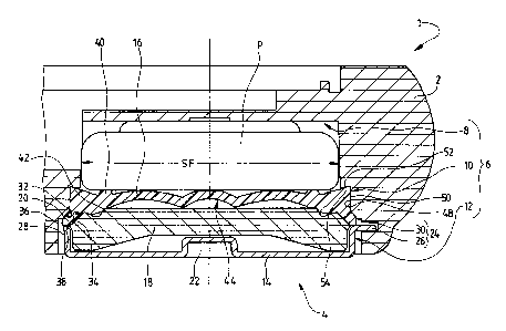
But other characteristics and advantages of the invent-
ion will appear upon reading the detailed description which
follows, made with reference to the single attached figure
which represents, in cross-section, a timepiece according
to the invention.
DESCRIPTION OF THE PREFERRED EMBODIMENT
As is seen on said figure, the timepiece according
to the invention which is here designated by the general
reference 1, includes a case 2 formed of an organic
material such as a thermoplastic material, for example,
of acrylonitrile butadiene styrene referenced under the
abbreviation ABS.

~.? ~J.~, ~3~~;
- 4 -
With such case 2, of which only those portions neces-
sary for understanding of the invention have been shown,
are generally associated a crystal, a dial as well as a
movement and hands, not shown.
On the interior of case 2 is arranged a cell compart-
ment 4 which is constituted by a stepped housing 6 formed
on the interior of case 2 in order to receive an electrical
energy source P, formed by a button cell of known type.
To this effect, electrical contact elements, also
not shown, are generally arranged within the cell compart-
ment 4 in order to assure electrical contact between th.e
positive and negative terminals of the cell, and the electr-
ical and electronic components of the timepiece according
to the invention.
The stepped housing 6 of the cell compartment 4 incl-
udes three characteristic portions: a bottom portion 8
which receives cell P as well as the associated electrical
contact elements, not shown, an intermediate portion 10
receiving more specifically a gasket seal which will be
described hereinafter, and an entrance portion 12 receiving
a cap 14 for closing the compartment 4.
Furthermore, the timepiece according to the invention
includes a gasket seal 16 which is advantageously formed
by a seal with a full lip extending, as is clearly seen
on the attached figure, over the entire frontal surface
SF of the cell P.
Such lip seal 16 which includes no discontinuity from
its most exterior peripheral edge towards the center is
constituted by an elastomeric material such as nitrile,
or vulcanized rubber.
The cell cap 14 includes an intermediate stopper 18

2.~~9388
likewise formed of an organic material such as a
thermoplastic, for example polyoxymethylene referenced
under the abbreviation POM and sold under the trademark
"Delrin".
The stopper 18 is distinct from the cap 14 and set
into the latter.
Such intermediate stopper 18 is freely housed in cap
14 with radial play and it is in direct bearing on a periph-
eral lip 20 formed on the gasket seal 16. The cell cap
14 which is formed by a swaged thin metallic sheet includes
in its central portion an actuating notch 22 in which can
be inserted a tool such as a coin in order to assure rotat-
ion of cap 14 and thus its opening and its closing. It
will here be noted that cap 14 turns alone independently
of stopper 18 which remains fixed in contact with seal
16.
To this effect, the timepiece according to the invent-
ion includes latching means 24 constituted by a bayonet
system of known conception. Such system is constituted
by several radial tongues 26 (a single one here being shown)
extending radially from. the peripheral edge 28 of cap 14
towards the exterior and engaging in a circular groove
30 which is formed in case 2 and which opens out radially
into the entrance portion 12 of housing 6.
Thus, it is noted that the entrance portion 12 of
housing 6 which is the stepped portion of such housing
exhibiting the greatest diameter basically receives cap
14 and its stopper 18 as well as the latching means 24
described hereinbefore.
As is seen on the attached figure, lip 20 of the gasket
seal 16 rests on a tapered bearing surface 32 formed in
case 2 between the entrance portion 12 of housing 6 and
the intermediate portion 10 of the latter. The tapered

2109388
- 6 -
bearing surface 32 opens out towards the entrance of hous-
ing 6 with a slope of about 45° angle. Lip 20 is thus
confined between such first tapered bearing surface 32
and a second tapered bearing surface 34 of substantially
the same angle as the first, in this case formed on stopper
18 at the periphery of the latter. It is noted in other
respects that lip 20 extends beyond the two tapered bearing
surfaces respectively 32 and 34 which maintain it and that
it projects towards the exterior in the entrance portion
12 of housing 6, in the vicinity of the peripheral edge
28 of cap 14. It will also be noted that the projecting
portion of lip 20 forming the most extreme outer portion
of tl~e gasket seal 16 shows two faces at 90 ° , respectively
36 and 38 reinforcing the sealing function of the lip when
it is subjected to high pressure. It is seen thus that
during immersion of the timepiece in a liquid, such latter
can come to penetrate into the entrance portion 12 of hous-
ing 6 to come into contact with faces 38 and 36 of the
outer peripheral edge of lip 20.
Seal 16 includes furthermore a circular cheek 40 having
the form of a rib which extends axially towards cell P
and which is intended to come to rest in axial bearing
on a bottom of the latter. The stopper 18 includes to
this effect an interior corner 42 formed in the vicinity
of the tapered bearing portion 34 and compressing the seal
16 in line with the cheek 40 in order to assure axial bear-
ing of the cell P onto its electrical contacts, not shown.
It is thus understood that in addition to assuring
sealing of the housing 6 the lip seal 16~of the timepiece
according to the invention assures the axial bearing of
the cell P towards the bottom of housing 6 and in particul-
ar towards its bottom portion 8.
Seal 16 additionally includes a central bellows 44
which extends entirely under cell 6 at the interior of
the circular cheek 40, such bellows exhibiting two charac-

2~.0~38~
_~_
teristic bulging regions, one central and the other exterior
coaxial to the first.
The gasket seal 16 is radially maintained in case
2 and more specifically in the intermediate portion 10
of housing 6 by means of an intermediate cylindrical bearing
surface 48 formed at the entrance of the portion of housing
8 receiving the cell. A corresponding cylindrical bearing
surface 50 is formed on the periphery of the seal 16 in
a manner adjacent and contiguous to lip 20, such bearing
surface 50 being housed within the cylindrical bearing
surface 48 of housing 6 in order to assure adjustment and
radial positioning of seal 16 in case 2.
One also notes that the cylindrical bearing surface
48 formed in case 2 includes a reentrant edge 52 in which
is engaged a corresponding tapered edge 54 formed on the
lip seal 16 in a manner to be opposite lip 20.

Representative Drawing
A single figure which represents the drawing illustrating the invention.
Administrative Status

2024-08-01:As part of the Next Generation Patents (NGP) transition, the Canadian Patents Database (CPD) now contains a more detailed Event History, which replicates the Event Log of our new back-office solution.

Please note that "Inactive:" events refers to events no longer in use in our new back-office solution.

For a clearer understanding of the status of the application/patent presented on this page, the site Disclaimer , as well as the definitions for Patent , Event History , Maintenance Fee  and Payment History  should be consulted.

Event History

Description Date
Time Limit for Reversal Expired 2007-10-29
Letter Sent 2006-10-27
Inactive: IPC from MCD 2006-03-11
Grant by Issuance 2004-07-20
Inactive: Cover page published 2004-07-19
Pre-grant 2004-05-06
Inactive: Final fee received 2004-05-06
Notice of Allowance is Issued 2003-11-28
Letter Sent 2003-11-28
Inactive: Approved for allowance (AFA) 2003-11-13
Amendment Received - Voluntary Amendment 2003-07-16
Inactive: S.30(2) Rules - Examiner requisition 2003-03-06
Inactive: Application prosecuted on TS as of Log entry date 2000-09-01
Letter Sent 2000-09-01
Inactive: Status info is complete as of Log entry date 2000-09-01
All Requirements for Examination Determined Compliant 2000-08-24
Request for Examination Requirements Determined Compliant 2000-08-24
Application Published (Open to Public Inspection) 1994-05-12

Abandonment History

There is no abandonment history.

Maintenance Fee

The last payment was received on 2003-09-29

Note : If the full payment has not been received on or before the date indicated, a further fee may be required which may be one of the following

  • the reinstatement fee;
  • the late payment fee; or
  • additional fee to reverse deemed expiry.

Please refer to the CIPO Patent Fees web page to see all current fee amounts.

Fee History

Fee Type Anniversary Year Due Date Paid Date
MF (application, 4th anniv.) - standard 04 1997-10-27 1997-10-10
MF (application, 5th anniv.) - standard 05 1998-10-27 1998-10-13
MF (application, 6th anniv.) - standard 06 1999-10-27 1999-09-24
Request for examination - standard 2000-08-24
MF (application, 7th anniv.) - standard 07 2000-10-27 2000-09-27
MF (application, 8th anniv.) - standard 08 2001-10-29 2001-10-02
MF (application, 9th anniv.) - standard 09 2002-10-28 2002-09-30
MF (application, 10th anniv.) - standard 10 2003-10-27 2003-09-29
Final fee - standard 2004-05-06
MF (patent, 11th anniv.) - standard 2004-10-27 2004-09-27
MF (patent, 12th anniv.) - standard 2005-10-27 2005-09-26
Owners on Record

Note: Records showing the ownership history in alphabetical order.

Current Owners on Record
ETA SA FABRIQUES D'EBAUCHES
Past Owners on Record
JACQUES CRETTENAND
Past Owners that do not appear in the "Owners on Record" listing will appear in other documentation within the application.
Documents

To view selected files, please enter reCAPTCHA code :


To view images, click a link in the Document Description column. To download the documents, select one or more checkboxes in the first column and then click the "Download Selected in PDF format (Zip Archive)" or the "Download Selected as Single PDF" button.

List of published and non-published patent-specific documents on the CPD .

If you have any difficulty accessing content, you can call the Client Service Centre at 1-866-997-1936 or send them an e-mail at CIPO Client Service Centre.


Document
Description 
Date
(yyyy-mm-dd) 
Number of pages   Size of Image (KB) 
Representative drawing 1998-07-21 1 22
Claims 2003-07-16 2 79
Representative drawing 2003-11-14 1 17
Abstract 1995-06-09 1 19
Drawings 1995-06-09 1 24
Description 1995-06-09 6 196
Cover Page 1995-06-09 1 71
Claims 1995-06-09 2 82
Cover Page 2004-06-15 1 49
Reminder - Request for Examination 2000-06-28 1 116
Acknowledgement of Request for Examination 2000-09-01 1 178
Commissioner's Notice - Application Found Allowable 2003-11-28 1 160
Maintenance Fee Notice 2006-12-18 1 173
Fees 1998-10-13 1 34
Fees 1997-10-10 1 34
Correspondence 2004-05-06 1 33
Fees 1996-10-11 1 35
Fees 1995-10-13 1 40