Language selection

Search

Patent 2109582 Summary

Third-party information liability

Some of the information on this Web page has been provided by external sources. The Government of Canada is not responsible for the accuracy, reliability or currency of the information supplied by external sources. Users wishing to rely upon this information should consult directly with the source of the information. Content provided by external sources is not subject to official languages, privacy and accessibility requirements.

Claims and Abstract availability

Any discrepancies in the text and image of the Claims and Abstract are due to differing posting times. Text of the Claims and Abstract are posted:

  • At the time the application is open to public inspection;
  • At the time of issue of the patent (grant).
(12) Patent: (11) CA 2109582
(54) English Title: A METHOD FOR JOINING SPIRALLY WOUND THERMOPLASTIC PIPES TOGETHER
(54) French Title: METHODE D'ASSEMBLAGE DE TUYAUX THERMOPLASTIQUES
Status: Term Expired - Post Grant Beyond Limit
Bibliographic Data
(51) International Patent Classification (IPC):
  • B29C 65/30 (2006.01)
  • B29C 53/58 (2006.01)
  • B29C 65/00 (2006.01)
  • B29C 65/18 (2006.01)
  • B29C 65/42 (2006.01)
  • B29C 65/50 (2006.01)
  • B29C 65/70 (2006.01)
  • F16L 47/02 (2006.01)
(72) Inventors :
  • BLOMQVIST, GUNNAR (Finland)
(73) Owners :
  • OY KWH PIPE AB
(71) Applicants :
(74) Agent: MCCARTHY TETRAULT LLP
(74) Associate agent:
(45) Issued: 1998-09-15
(86) PCT Filing Date: 1992-06-12
(87) Open to Public Inspection: 1992-12-23
Examination requested: 1996-03-28
Availability of licence: N/A
Dedicated to the Public: N/A
(25) Language of filing: English

Patent Cooperation Treaty (PCT): Yes
(86) PCT Filing Number: PCT/FI1992/000185
(87) International Publication Number: WO 1992022419
(85) National Entry: 1993-11-19

(30) Application Priority Data:
Application No. Country/Territory Date
912880 (Finland) 1991-06-14

Abstracts

English Abstract


The present invention relates to a method for joining spirally wound thermoplastic pipes (1, 2) of a hole profile together,
characterized by the following steps: working the end surfaces (3, 4) of the spirally wound thermoplastic pipes (1, 2) into a
smooth step-formed surface; setting two thermoplastic pipes (1, 2) end against end such that a smooth step-formed gap is formed
between the end surfaces (3,4); applying a stainless steel band (5) over the gap and heating the steel band (5) to ca. 100 °C,
applying an extruder (6) with a rotating extruder head (6) and a cooled slide and smoothing organ (8) cooperating therewith inside
the pipes (1, 2) to be joined together; heating the end surfaces (3, 4); extruding a weld seam of a melted thermoplastic (9) into the
gap between the two end surfaces (3, 4); as well as stopping the heating of the steel band (5) and removal of the steel band (5)
from the joining place after cooling.


French Abstract

La présente invention concerne un procédé d'assemblage de canalisations thermoplastiques de construction hélicoïdale (1, 2) comportant les étapes suivantes : découpage des extrémités des canalisations (1, 2) pour obtenir une face régulière avec épaulement(s) (3, 4); aboutement des canalisations (1, 2) de manière à laisser un espace entre les faces d'extrémité (3, 4); mise en place d'une bande d'acier inoxydable (5) sur le joint et chauffage de la bande d'acier à une température d'environ 100 oC; insertion dans les canalisations (1, 2) à assembler d'un dispositif d'extrusion (6) à tête rotative (6) avec caniveau et organe de lissage (8) refroidis; chauffage des faces d'extrémité (3, 4) à assembler; extrusion d'une matière thermoplastique fondue (9) dans l'espace entre les faces d'extrémité (3, 4) pour former un joint; arrêt du chauffage de la bande d'acier inoxydable (5) et retrait de la bande (5) après refroidissement du joint.

Claims

Note: Claims are shown in the official language in which they were submitted.

WE CLAIM:
1. A method for joining spirally wound thermoplastic pipes
(1,2) together, comprising the steps of:
providing a first thermoplastic pipe (1) and a second
thermoplastic pipe (2) wherein each thermoplastic pipe comprises
a spirally wound hollow profile,
positioning an end of the first thermoplastic pipe (1)
adjacent an end of the second thermoplastic pipe (2) such that
a gap having a step is formed between an end surface (3) of the
end of the first pipe (1) and an end surface (4) of the end of
the second pipe (2),
applying a stainless steel band (5) around the end of the
first pipe and the end of the second pipe such that the band is
positioned over the gap and heating the steel band,
placing an extruder (6) and a cooled slide and smoothing
organ (8) inside the thermoplastic pipes (1,2),
heating the end surfaces (3,4) with a heating means,
extruding melted thermoplastic (9) into the gap between the
two end surfaces with said extruder, and applying pressure to the
melted thermoplastic with the slide and smoothing organ,
stopping the heating of the steel band, cooling the extruded
thermoplastic, and removing the steel band (5) after cooling.
2. A method according to claim 1, wherein the steel band (5)
is heated electrically.
3. A method according to claim 2, wherein the steel band (5)
is provided with a temperature sensor, and wherein a regulating
circuit maintains the temperature of the steel band at a desired
level based upon readings from said temperature sensor.
4. A method according to any one of claims 1-3, wherein said
gap is about 10-20 mm wide.
5. A method according to claim 4, wherein the steel band (5)
is teflon coated.

6. A method according to claim 5, wherein the steel band is
surrounded with a felt cloth (10) and a rubber sleeve (11)
surrounds the felt cloth (10).
7. A method according to any one of claims 1-3, wherein the
heating means is a warm-air blower (12) and the end surfaces are
heated with warm air coming from the warm air blower before the
thermoplastic is extruded.
8. A method according to claim 1, wherein said step of heating
the steel band includes heating the steel band to about 100°C.

Description

Note: Descriptions are shown in the official language in which they were submitted.


~092/22419 210 9 3 8 ~ PCT/F192/00185
A METHOD FOR JOINING SPIRALLY WOUND THERMOPLASTIC PIPES
TO~l~
The invention relates to a method for Joining spirally
wound thermoplastic pipes of a hole profile together.
,
According to earlier methods, the join:ing-together of
spirally wound pipes of the above-mentioned type usually
occurred by ~eans of extruder welding fro~ the outer and
inner side of the pipe. Since pipes of very large
diameters, 2 m or more, are often concerned, this
previously known technique causes considerable technical
prob~ems, and it is simultane~usly very time-consuming. It
was very diffucult to reach a satisfactory final result by
means of the previously known technique.
:::
: The object of the pre ent invention is to eli m; n~te these
problems, which is achieved by means ~f a method, which is
characterized by the fol~owing steps:
~
working the end surfaces of the sprirally wound
he ~ plastic pipes into a smooth step-form~d surface,
-.settiny two thermoplastic pipes end against end such tha~
ZS à smooth s~ep-formed gap is formed between the end
sur~aces~ ~
applyins~ a stainless -~teel band over the gap and heating
of ~he steel band to ca. 10~~C,
30: ~
- applying an extruder with a rotating extruder head and a
cooled slide and smoothing organ cooperating therewith
: inside the pipes to be joined together,
- heati~g the end surfaces,
:

WO92/2~14 q ~ ~ PCT/F192/OD
- extruding a weld seam o~ a melted thermopiastic into the
gap between the two end surf aces, as well as
- 5topping the heating of the steel band and ~e-u~vlng the
5 steel band from the ~oining p~ ace after cooling.
The remai~ing characteristics of the inv~ntion will be
apparent from the ~nclosed claims 2-7.
The invention will next be described in more detail with
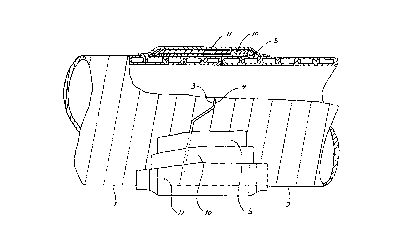
reference to the ~o~J~ anying drawing, wher~in
Fig. l shows the joining-together of two spirally wound
pipes according to the present invention, seen from the
outside in a radial direction, and
Fig. 2 shows the joining-together of Fig. l, seen in an
~ ~ aa~ial directionO
20 Th~ joining-tog~ther o~ spirally wound thermoplastic pipes
1, 2 made of a: hole profile occurs according to the
invention as f ol l ows . The ends of the two thermoplastic
plpes 1, 2 to ~e ~ oined together are worked such that an
end opening of the corr s~on~ hole profile is closed and
25 two smooth :s~ep-formed end surfaces 3, 4, which f~
~ ,.
~ together, are obt~in~, whereafter the tws pipes are placed
:
: end against end and ~-et such that a uniformly wide s~ep
fvrmed gap fonms b~tw~en the end surfaces 3 and 4. The gap
width is to be fitted according to the radial dimension of~ ~ 30 :the hole profilP, of which the spirally woun,d pipe l, 2,is
comprised. In ~ ~nn~ction with the most usual pipe
~e~;ons, the gap:~width ~aries in the range of lO-40 mm.
A stainless steel ~and 5 is applied over the gap between
~ .
the two thermoplastic pipes l, 2 and is heated to ca. lO0
~~. In order to avoid that the melt~d thermoplastic
material will adhére to the steel band S, it is preferably
teflon coated. ~n extruder 6 w~th a rotating extruder head

, ~092/2~19 2 1 0 9 ~ 8 2 PCT/F192/00185
7 and a cooled slide and smoothing organ d cooperating
~herewith are applied inside the pipes l, 2 to be joined
together. The end surfaces 3, ~ are heated e.g. with warm
air coming from a warm-air blower 12. A weld seam of melted
S thermoplastic 9 is extruded lnto the gap between the two
end surfaces 3, 4, whereby the slide and smuothing'organ 8
brings about the fact that the melted thermoplastic 9
completely fills the gap and a weld pressure is obtained.
In this way, a weld seam with a smooth inner surface is
formed. After the extrusion of the whole gap is completed,
the h2atin0 of the steel band 5 is stopped a~d the extruded
thermoplastic seam is cooled, whereafter the steel band 5
is removed from the Joining place. A very smoooth seam may
then be observed, which is nearly invisible to the naked
eye.
Ac~ording to a preferr~d~ embodiment, the heating of the
: steel ban~ 5 occu~s electri~ally, preferably by short-
~ircuiting.
For s~tting the t mperature of the steel ~and 5 to ~he
: :d~sir~d: le~el, it m~ay preferably be provided with a
temperature sensor ~oupled to a regulating c~rcuit, which
is~arranged-to:regulate the electricity supply to the steel
~band.~
:
: The:joining-place,;~:after the steel band 5 has been~applied,
has preferably to be surrounded with an insulation layer,
: as well as a felt cloth lO, which is in turn surrounded
:30 with: a rubber sleeve ll, which p~vel~ts moisture and
, wetness from comi n~ into contact with the steel- band S,
:whic~ may detrimentally affect the heating cycIe.
~:

Representative Drawing
A single figure which represents the drawing illustrating the invention.
Administrative Status

2024-08-01:As part of the Next Generation Patents (NGP) transition, the Canadian Patents Database (CPD) now contains a more detailed Event History, which replicates the Event Log of our new back-office solution.

Please note that "Inactive:" events refers to events no longer in use in our new back-office solution.

For a clearer understanding of the status of the application/patent presented on this page, the site Disclaimer , as well as the definitions for Patent , Event History , Maintenance Fee  and Payment History  should be consulted.

Event History

Description Date
Inactive: Expired (new Act pat) 2012-06-12
Inactive: IPC from MCD 2006-03-11
Grant by Issuance 1998-09-15
Pre-grant 1998-04-14
Inactive: Final fee received 1998-04-14
Notice of Allowance is Issued 1998-03-03
Letter Sent 1998-03-03
Inactive: Status info is complete as of Log entry date 1998-02-25
Inactive: Application prosecuted on TS as of Log entry date 1998-02-25
Inactive: IPC removed 1998-02-09
Inactive: First IPC assigned 1998-02-09
Inactive: IPC assigned 1998-02-09
Inactive: Approved for allowance (AFA) 1998-02-06
All Requirements for Examination Determined Compliant 1996-03-28
Request for Examination Requirements Determined Compliant 1996-03-28
Application Published (Open to Public Inspection) 1992-12-23

Abandonment History

There is no abandonment history.

Maintenance Fee

The last payment was received on 

Note : If the full payment has not been received on or before the date indicated, a further fee may be required which may be one of the following

  • the reinstatement fee;
  • the late payment fee; or
  • additional fee to reverse deemed expiry.

Please refer to the CIPO Patent Fees web page to see all current fee amounts.

Owners on Record

Note: Records showing the ownership history in alphabetical order.

Current Owners on Record
OY KWH PIPE AB
Past Owners on Record
GUNNAR BLOMQVIST
Past Owners that do not appear in the "Owners on Record" listing will appear in other documentation within the application.
Documents

To view selected files, please enter reCAPTCHA code :


To view images, click a link in the Document Description column. To download the documents, select one or more checkboxes in the first column and then click the "Download Selected in PDF format (Zip Archive)" or the "Download Selected as Single PDF" button.

List of published and non-published patent-specific documents on the CPD .

If you have any difficulty accessing content, you can call the Client Service Centre at 1-866-997-1936 or send them an e-mail at CIPO Client Service Centre.


Document
Description 
Date
(yyyy-mm-dd) 
Number of pages   Size of Image (KB) 
Cover Page 1998-08-25 1 57
Abstract 1995-08-05 1 80
Cover Page 1995-08-05 1 36
Drawings 1995-08-05 1 48
Claims 1995-08-05 2 90
Description 1995-08-05 3 198
Claims 1998-01-07 2 58
Representative drawing 1998-08-25 1 8
Commissioner's Notice - Application Found Allowable 1998-03-03 1 165
Fees 2003-05-30 1 24
Fees 2002-05-22 1 33
Correspondence 1998-04-14 1 33
Fees 1998-06-08 1 43
Fees 2001-05-24 1 44
Fees 1997-06-04 1 42
Fees 1999-05-25 1 41
Fees 2000-06-01 1 37
Fees 2004-05-20 1 26
Fees 2005-06-08 1 26
Fees 2006-05-15 1 25
Fees 2007-05-09 1 25
Fees 2008-05-14 1 27
Fees 2009-05-27 1 34
Fees 2010-05-27 1 37
Fees 2011-06-01 1 37
Fees 1996-05-22 1 52
Fees 1993-11-19 1 40
International preliminary examination report 1993-11-19 9 284
Prosecution correspondence 1996-03-28 1 31
Courtesy - Office Letter 1996-04-22 1 41
Prosecution correspondence 1996-03-28 1 38