Language selection

Search

Patent 2109583 Summary

Third-party information liability

Some of the information on this Web page has been provided by external sources. The Government of Canada is not responsible for the accuracy, reliability or currency of the information supplied by external sources. Users wishing to rely upon this information should consult directly with the source of the information. Content provided by external sources is not subject to official languages, privacy and accessibility requirements.

Claims and Abstract availability

Any discrepancies in the text and image of the Claims and Abstract are due to differing posting times. Text of the Claims and Abstract are posted:

  • At the time the application is open to public inspection;
  • At the time of issue of the patent (grant).
(12) Patent: (11) CA 2109583
(54) English Title: A DEVICE FOR CUTTING PLYWOOD VENEER
(54) French Title: DISPOSITIF POUR COUPER DU PLACAGE DE CONTREPLAQUE
Status: Expired and beyond the Period of Reversal
Bibliographic Data
(51) International Patent Classification (IPC):
  • B27L 05/08 (2006.01)
  • B26D 01/62 (2006.01)
  • B26D 11/00 (2006.01)
  • B27C 01/10 (2006.01)
  • B27G 01/00 (2006.01)
(72) Inventors :
  • SINTONEN, KARI (Finland)
(73) Owners :
  • RAUTE WOOD PROCESSING MACHINERY OY
(71) Applicants :
  • RAUTE WOOD PROCESSING MACHINERY OY (Finland)
(74) Agent: MCCARTHY TETRAULT LLP
(74) Associate agent:
(45) Issued: 2004-02-03
(86) PCT Filing Date: 1992-03-27
(87) Open to Public Inspection: 1993-01-07
Examination requested: 1998-11-17
Availability of licence: N/A
Dedicated to the Public: N/A
(25) Language of filing: English

Patent Cooperation Treaty (PCT): Yes
(86) PCT Filing Number: PCT/FI1992/000091
(87) International Publication Number: FI1992000091
(85) National Entry: 1993-11-19

(30) Application Priority Data:
Application No. Country/Territory Date
913111 (Finland) 1991-06-26

Abstracts

English Abstract


The invention concerns a veneer cutter for cutting off the faulty spots, and
for cutting the veneer into sheets at certain
intervals. The cutter is furnished with rotatable blade, which consists of two
independently controllable sections.


Claims

Note: Claims are shown in the official language in which they were submitted.

4
Claims:
1. A device for cutting a veneer web into sheets
of certain width and for removing faulty spots
by means of a cutting blade structure (2), the
cutting blade structure comprising an elongated
shaft (1) having two opposite free ends for sup-
porting the shaft, and two cutting blade ele-
ments (2', 2'') rotatably supported on the shaft
between the free ends of the shaft, said cutting
blade elements each having a cutting blare ex-
tending alone the length of the shaft, each of
the cutting blades having at least one cutting
cutting blade elements (2', 2'') being rotatable
on the shaft independent of the rotation of the
other cutting blade element, said cutting blade
elements forming a contiguous cutting blade ex-
tending across the shafts when in unison with
each other.
2. The device in accordance with claim
characterized in that each of the cutting blade
elements (2', 2'') extends to half-way across
the veneer web to be cut.
3. The device in accordance with claim 1 or 2,
characterized in that each of the cutting blade
elements (2', 2'') have two opposite cutting
edges on a same distance from the axis of rota-
tion of the shaft (1).
4. The device in accordance with any of claims 1
to 3, characterized in that the cutting blade
(2) is arranged to cut the veneer web against a

5
supporting roller while at the same time behind
abutting on a supporting organ.
5. The device in accordance with claim 4, cha-
racterized in that the shaft (1) is under ten-
sile stress.
6. The device in accordance with any of claims 1
to 3, characterized in that the cutting blade
(2) is mounted onto a shaft (1) that is solid
enough to provide the cutting blade with suffi-
cient support for the execution of a veneer cut-
ting operation.

Description

Note: Descriptions are shown in the official language in which they were submitted.


i
CA 02109583 2002-10-02
A device for cutting plywood veneer
The object of the invention is a device for cutting ply-
wood veneer.
Background of Invention
The device is intended for cutting the veneer web issuing
io forth from a plywood lathe. The cutting is executed
either so that the faulty spots are cut off or the veneer
web is cut into sheets of certain width at set intervals.
The device is especially intended for a veneer cutting
application in which the veneer web cut off a log is slit
into two parts in the longitudinal direction, i.e. in the
direction of motion of the veneer web in so far as the
web has faulty spots. The slitting is normally executed
essentially along the middle of the web. Following the
implementation of this method, the faults are removed
ao independently from either part of the veneer web, whereas
the sound part of the web is cut to set widths along the
entire web without slitting it.
While the said method does save web, because faulty spots
as seldom extend very far across the web, it also imposes
great demands on the cutting apparatus. In applications
of this method it is known for more than one slitter to
be used; that is to say, two narrow slitters are used for
cutting off the faulty spots in the two halves of the web
3o and one full-size slitter is used for cross cutting ccxnp-
lete web sections.
Summary of the Invention
35 The invention that is the subject cf this application
brings about an essential improvement to the said problem
in that the device in accordance with the invention makes
it possible to execute both the cutting off of faulty

i
CA 02109583 2002-10-02
2
spots in the web halves as well as the cutting into set
widths of complete web sections. The device in accordance
with the invention is based on what may be called the
technique of a rotary-blade nutter which embodies a
s cutting blade reaching across the web to be cut, the said
cutting blade lending itself to be rotated in a con-
trolled manner into cutting contact with a selected cut-
ting point on the veneer web. The rotary motion flf the
said cutting blade has been selected to be such that it
~o complies with the forward motion of the veneer web where-
upon the cutting blade does not cause the veneer web to
be arrested on being cut.
Usually this type of a cutting blade works in unison with
i5 a roller supporting the veneer web or with a correspon-
ding opposing organ against which the cutting blade is
forced in order for the cutting action to be executed.
The cutting blade can be made to sufficiently massive for
the cutting operation to occur successfully. The said
2o massiveness of the cutting blade may be achieved, for
instance, by making the shaft sufficiently solid. Alter-
natively, the cutting apparatus may embody an abutting
organ on the side opposite to the cutting blade, the said
abutting organ providing the cutting blade with ~su~port
2s for the cutting operation to be executed. The stiffness
of a structurally light cutting blade can be increased by
subjecting the shaft to tensile stress when in use.
In accordance with the invention, the said cutting blade
3o element is divided into two consecutive sections along
its shaft, the rotational position of the said elements
being such that they can be controlled independently.
Brief Description of the Drawings
The invention is described by means of the appended dra-
wings, wherein:

i I
CA 02109583 2002-10-02
3
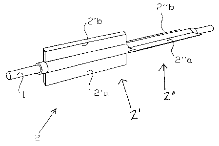
Fig. 1 is one view of the inventive cutting blade
arrangement of the present invention showing the inde-
pendent operation of the cutting blades;
s Fig. 2 is another view of the inventive cutting blade
arrangement of the present invention with the cutting
blades in unison.
Detailed description of the preferred embodiments
io
The drawing shows the cutting blade arrangement in accor-
dance with the invention, the said arrangement embodying
a shaft 1 reaching across the entire veneer web that is
to be cut and the two cutting blade elements 2' and 2 "
is supported by it. The cutting blade elements may be ro-
tated independently on the shaft 1 and they are provided
with their own rotating apparatus. When the slit veneer
web passes underneath the cutting blade structure 2, and
it contains random faults on one half or the other or
2o simultaneously on both halves, the cutting blade elements
2' and 2 " execute cutting operations on the web halves
independently on one another in order to remove faulty
spots from their respective halves.
2s Once the peeling of the veneer web has proceeded onto the
sound part of the peeled log, the slitting of the veneer
web coming to the slitter is discontinued and the control
for the cutting blade elements 2' and 2 " are combined to
obey the same command, this command usually being to cut
3o the veneer web into sheets of certain width. When execut-
ing this function, the cutting blade elements 2' and 2 "
are, of course, angularly in unison with one another and
form a contiguous cutting blade reaching across the ve-
neer web. The said joint-function model may include situ-
3s ations in which the veneer web contains faulty spots that
need to be removed. When this is the case, the faulty
spots are cut off in strips extending across the entire

i i
CA 02109583 2002-10-02
4
veneer web by the cutting blade elements 2' and 2 " work-
ing in unison.
In deviation from the above execution model, where the
s cutting blade elements 2' and 2 " are composed of two
cutting blades 2'a, 2'b, and correspondingly 2 " a , 2 " b,
the cutting blade elements may consist more cutting
blades; e.g. four cutting blades positioned at even an-
gles on a shaft. Even one cutting blade per cutting blade
to element 2' and 2 " forms a functioning solution.

Representative Drawing
A single figure which represents the drawing illustrating the invention.
Administrative Status

2024-08-01:As part of the Next Generation Patents (NGP) transition, the Canadian Patents Database (CPD) now contains a more detailed Event History, which replicates the Event Log of our new back-office solution.

Please note that "Inactive:" events refers to events no longer in use in our new back-office solution.

For a clearer understanding of the status of the application/patent presented on this page, the site Disclaimer , as well as the definitions for Patent , Event History , Maintenance Fee  and Payment History  should be consulted.

Event History

Description Date
Time Limit for Reversal Expired 2011-03-28
Letter Sent 2010-03-29
Inactive: Correspondence - Formalities 2006-03-14
Inactive: IPC from MCD 2006-03-11
Grant by Issuance 2004-02-03
Inactive: Cover page published 2004-02-02
Pre-grant 2003-11-21
Inactive: Final fee received 2003-11-21
Notice of Allowance is Issued 2003-06-16
Letter Sent 2003-06-16
Inactive: Approved for allowance (AFA) 2003-06-04
Amendment Received - Voluntary Amendment 2003-03-05
Inactive: S.30(2) Rules - Examiner requisition 2002-12-10
Inactive: Adhoc Request Documented 2002-12-10
Amendment Received - Voluntary Amendment 2002-10-02
Inactive: S.30(2) Rules - Examiner requisition 2002-08-08
Inactive: RFE acknowledged - Prior art enquiry 1998-12-14
Inactive: Status info is complete as of Log entry date 1998-12-14
Inactive: Application prosecuted on TS as of Log entry date 1998-12-14
Request for Examination Requirements Determined Compliant 1998-11-17
All Requirements for Examination Determined Compliant 1998-11-17
Application Published (Open to Public Inspection) 1993-01-07

Abandonment History

There is no abandonment history.

Maintenance Fee

The last payment was received on 2003-03-27

Note : If the full payment has not been received on or before the date indicated, a further fee may be required which may be one of the following

  • the reinstatement fee;
  • the late payment fee; or
  • additional fee to reverse deemed expiry.

Patent fees are adjusted on the 1st of January every year. The amounts above are the current amounts if received by December 31 of the current year.
Please refer to the CIPO Patent Fees web page to see all current fee amounts.

Owners on Record

Note: Records showing the ownership history in alphabetical order.

Current Owners on Record
RAUTE WOOD PROCESSING MACHINERY OY
Past Owners on Record
KARI SINTONEN
Past Owners that do not appear in the "Owners on Record" listing will appear in other documentation within the application.
Documents

To view selected files, please enter reCAPTCHA code :


To view images, click a link in the Document Description column (Temporarily unavailable). To download the documents, select one or more checkboxes in the first column and then click the "Download Selected in PDF format (Zip Archive)" or the "Download Selected as Single PDF" button.

List of published and non-published patent-specific documents on the CPD .

If you have any difficulty accessing content, you can call the Client Service Centre at 1-866-997-1936 or send them an e-mail at CIPO Client Service Centre.

({010=All Documents, 020=As Filed, 030=As Open to Public Inspection, 040=At Issuance, 050=Examination, 060=Incoming Correspondence, 070=Miscellaneous, 080=Outgoing Correspondence, 090=Payment})


Document
Description 
Date
(yyyy-mm-dd) 
Number of pages   Size of Image (KB) 
Representative drawing 1998-12-13 1 5
Claims 2003-03-04 2 52
Representative drawing 2003-06-12 1 7
Claims 1995-09-08 1 42
Description 1995-09-08 3 153
Abstract 1995-09-08 1 37
Drawings 1995-09-08 1 17
Claims 2002-10-01 2 49
Drawings 2002-10-01 1 14
Description 2002-10-01 4 151
Reminder - Request for Examination 1998-11-29 1 116
Acknowledgement of Request for Examination 1998-12-13 1 172
Commissioner's Notice - Application Found Allowable 2003-06-15 1 160
Maintenance Fee Notice 2010-05-09 1 170
PCT 1993-11-18 10 323
Fees 2003-03-26 1 35
Correspondence 2003-11-20 1 29
Fees 1999-02-21 1 41
Fees 2000-01-27 1 38
Fees 1998-03-25 1 39
Fees 2001-03-07 1 36
Fees 2002-03-07 1 37
Fees 2004-02-01 1 26
Fees 2005-01-09 1 26
Correspondence 2006-03-13 1 25
Fees 2006-03-13 1 25
Fees 2007-03-13 1 24
Fees 2008-02-05 1 25
Fees 2009-01-22 1 35
Fees 1997-03-25 1 48
Fees 1996-03-05 1 47
Fees 1995-02-23 1 47
Fees 1993-11-18 1 40