Note: Descriptions are shown in the official language in which they were submitted.
. - -I 2109g71
~A METALLIC CAN SEAMING PROCESS~
The object of the present invention patent is a metallic can
manufacturing process and refers particularly to the means
of seaming the top and the bottom by which, due to a subs-
tancial reduction of the`dimensions of the hooks and other
fixing folds, a considerable and advantageous reduction of
the diameters of the cut-outs of the material employed for
the manufacture of the top and end of a can is obtained, as
well as, consequently, a significative reduction of the
height of the can body and this without change of the
holding capacity of the can. This is a process from which
substantial savings of metal sheet result, both in quantity
as well as by employing a thinner and harder sheet metal, i.
e., of 0,16mm thickness and by using DR8 heat treatment, the
price of which is 21.2 to 28.3% lower than that of the
conventionally used metal sheet, i.e., of 0.22 to 0,24mm
thickness and the normal temper required
As is known to those with knowledge of the matter, the
currently used conventional cans designed to serve as
packing for the most diverse products, particularly for
food products and the so-called sanitary cans, are normally
obtained by using tinplate of 0.22 to 0.24mm thickness with
the normal temper required for the top and the end of a-can,
features which would also allow the employment of this metal
sheet for micro-seaming, however, without the advantages of
large savings of 21.2 to 28.3% obtained a~ a result of the
use of a metal sheet of 0.16mm thickness and DR8 temper, as
outlined by this new process.
,
The subject new metallic can manufacturing process will
provide substantial savings, both by the substantial
reduction of diameters of the cut-outs for the top and the
end of a can, and this as a consequence of the reduction of
the dimensions of the hooks and other fixing folds, as well
as by the reduction of height provided to the can body
without changing its holding capacity, savings which become
- 2 - ~109871
more significant due to the employment of a thinner and
harder metal sheet, i.e. of 0.16mm thickness with DR8 temper,
as compared to the conventionally used metal sheet of 0.22 to
0.24mm thickness and the normal temper required for the top
and the end of a can.
This new process is possible for metallic can with an electri-
cally welded (3 piece cans) or deep drawn body (2 piece cans),
i.e., those bodies with no lap or two thicknesses where the
joint is obtained by folds soldered with tin or lead or
thermoplasts, a condition which renders this new process
infeasible.
The new metallic can manufacturing process as stated before is
represented in the attached drawings which show, for comparison
purposes, both the cut-out discs of the top and end, as well as
the fixed parts and the can body, with their respective
dimensions, as follows:
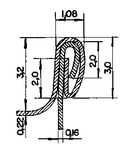
Fig. 1 is a sectional view, showing the seam obtained by
the conventional process, i.e., by employing a metal
sheet of 0.22mm thickness with relatively larger
seaming dimensions;
Fig. 2 is a sectional view, showing a micro-seam obtained
by the new process, i.e., by employing a metal sheet
of lesser thickness, i.e., 0.16mm and a harder one,
i.e., with DR8 temper, of which the seaming
dimensions are considerably reduced in comparison
with the conventional process;
Fig. 3 is a side view of a r.eady or seamed can with
conventional seam, thé height of its body being
considerably greater as compared to the can obtained
by the new seaming process;
Fig. 4 is a side view of a ready or seamed can, the seam
of whicn has been o~tained by the new process, the
height of its body showing to be considerably lower,
without cha~ging its volumetric capacity;
. ~ 3 ~ ~l ~9~7 1
Fig. S is a top view of the disc designed for the top and
end of a can, cut with the normally used diameter
employed with conventional seaming process;
Fig. 6 is a top view of a disc designed for the top and
end of a can, ~cut with a considerably smaller
diameter, used for the micro-seaming and in
accordance to the object of the new process;
Fig. 7 is a top view of an already stamped top and end of
a can, according to the dimensions used for
conventional seaming process;
Fig. 8 is a top view of an already stamped top and end of
a can, according to the dimensions used for the new
seaming process;
Fig. 9 is a sectional view of an already stamped top and
end of a can, showing the profile and curling
dimensions used for conventional seaming process;
Fig. 10 is a sectional view of an already stamped top and
end of a can, showing the profile and reduction of
curling dimensions for the new seaming process;
Fig. 11 is a side view of a cylindrical can body with
the height dimension designed for conventional
seaming process;
Fig. 12 is a side view of a cylindrical can body with the
considerably reduced heiqht, destinated for the
new micro-seaming process;
Fig. 13 is a side view of a flanged can body and its
dimensions normally used for conventional seaming
process;
Fig. 14 side view of a flanged can body showing sensibly
reduced dimensions according to the micro-
seaming process;
.. ... . , . . ,. .. . .. . , . _. .
, ~ 4 ~ ~ 109871
Fig- 15 is a diagram of seamer head chuck and rolls used
for seaming the cans;
Fig. 16 shows a profile and dimensions of a first seam roll
for micro-seam;
Fig. 17 shows aprofile and dimensions of a second seam roll
for micro-seam;
Fig. 18 is a side view of the cover or can end and the can
body before the first seaming operation;
Fig. 19 is a side view of the micro-seam after the first
seam roll operation;
Fig. 20 is a side view of the micro-seam after the second
seam roll operation;
Fig. 21 shows a profile and dimensions of a first seam roll
for conventional seam;
Fig. 22 shows a profile and dimensions of a second seam roll
for conventional seam;
Fig. 23 is a side view of the conventional seam after the
first seam roll operation; and
Fig. 24 is a side view of the conventional seam after the
second seam roll operation.
Describing in more detail the new can manufacturing process
consists in using seaming equipment well known in the art.
Seaming operations are currently effected by using a type
of machine of which the essential components are comprised
of at least (Fig. 15); one or more stations for the closing
machine, having a base plate 8, a seaming chuck 1, at least
one first operation roll 4, and one second operation roll 5.
The base plate; or can holding chuck, of the machine, supports
the can body 6. The snug fitting seaming chuck holds the can
cover (can end) 7 in place on the can body and acts as a
back-up for the seaming roll pressure.
The current micro-seaming uses seaming equipment exactly
the same as the tradi~ional seaming equipment described above,
except for the redesigning and redimensioning of the first
and second operation rolls (Figs 16 and 17).
f~09871
~he redesigning and redimensioning of the first and second
operation rolls vary according to the thickness and hardness
of the metallic material as well as the diameter of the can.
This applies both to cans produced by micro-seaming and cans
produced by conventional seaming. Therefore, the designs and
dimensions of the first and second operation rolls shown in
Figs. 16 and 17 are valid for micro-seaming can ends ( to
bodies of cans) with 73mm diameter produced with 0.16mm
thick material and DR8 temper. Comparatively the Figs. 21
and 22 show the designs and dimensions of the first and
second operation rolls for conventionally seaming can ends
~to bodies of cans) with 73mm diameter produced with 0.22
thick material and T61 hardness.
The above example is one illustration of micro-seaming. It
is unde~tood that other dimensions can be used for micro-
seaming and the present application is not limited to this
one example.
Consequently, for can ends having diameters greater or
smaller than 73mm, the measurements shown in Figs. 16, 17,
21 and 22 (units are calibrated in mm) should be revised
accordingly with reference to the above illustrated example.
This applies both to conventional seaming and micro-seaming.
All the stages of formation of micro-seam are illustrated
in Figs. 18, 19, 20 and 2. In the first operation, Figs. 18
and 19, the micro-curl of the end is interlocked (sometimes
referred to as engaged) with the micro-flange 3 of the can
body of a first operation roll 4 having a specially
contoured groove to be pressed against the seaming chuck 1.
After the first seam operation is completed, the first
operation roll is retracted and no longer contacts the can
cover (can end). The second operation roll 5 (Fig. 20) has
a different groove profile from that of the first operation
roll. This groove is flatter than the first operation
groove and is designed to press the preformed hooks
together; to iron out wrinkles in the cover hook and to
obtain micro-seam tightness. A good and uniform seaming is
obtained with this new can manufacturing process and with
, . ... ..... ..
- 6 ~ 210987 ~
Sp~cial measurements in the cover hook, body hook, length
of the micro-seam and other folds (see Fig. 2).
The designing of the curves and dimensioning of the first
and second operation rolls for a conventional seam are
shown in Figs. 21 and~22. All the stages of formation of a
conventional seam are illustrated in Figs. 23 and 24. In
the first operation, Fig. 23, the curling of the can end 10
is interlocked with the flange 11 of the can body of a first
operation roll 12 having a specially contoured groove to be
pressed against the seaming chuck 1. After the first seam
operation is completed, the first operation roll 12 is
retracted and no longer contacts the can cover (can end).
The second operation roll 13 (Fig. 24) has a different
groove profile from that of the first operation roll. This
groove is flatter than the first operation groove and is
designed to press the preformed hooks together to obtain a
seam tightness with special measurements in the cover hook,
body hook, length of seam and other folds (see Fig. 1).
The micro-seam improvements enables one to obtain cans with
substantial materials savings, due to the use of a thinner
metal sheet, i.e., of 0.16mm thickness which is relatively
harder, i.e., with DR8 temper, thus replacing the conventio-
nally used metal sheet for the known seaming process, where
what is normally employed is a metal sheet of 0.22 to 0.24mm,
which is relatively softer, and this without affecting the
volumetric capacity of the cans thus obtained.
This new can manufacturing process allows many advantageous
material savings, these savings result from the considerable
reduction of the diameters of the discs which form the top
and end of a can, as shown in Figs. 5 and 6, as well as a
reduction of the hooks dimensions and others seaming
dimensions as shown on Figs. 1 and 2 and Figs. 9 and 10 in
addition more material savings result from a reducdtion of
the heigth of the cylindrical body of the can, as shown on
Figs. 3 and 4 and on Figs. 11 through 14 of the attached
drawings. These reductions are obtained without affecting
the volumetric capacity of the cans thus obtained through
the new micro-seaming process.
~ 7 ~
~or a perfect evaluation of the actua~ ~ Q~t7ages resulting
from this new process it is worthwile to note that, in
addition to this substan~ial materials savings, allowed by
the use of a double reduced metal shee~, i.e., with DR8
temper and 0.16mm thickness in manufacturing of the tops
and ends of cans, the~use of this lower price metal sheet
is not possible for the conventional type of seaming. The
high hardness of the material and its thinness would cause
folds on the hooks to develop enormous deformations which
would be transmitted into a general seaming deformation
which, in addition to an extremely bad appearance of the
can, leading to its technical condemnation for not providing
a perfect seal and, consequently, an ideal hermetic seam,
which represent the fundamental requirements of a good
seaming and quality of these containers.