Language selection

Search

Patent 2110035 Summary

Third-party information liability

Some of the information on this Web page has been provided by external sources. The Government of Canada is not responsible for the accuracy, reliability or currency of the information supplied by external sources. Users wishing to rely upon this information should consult directly with the source of the information. Content provided by external sources is not subject to official languages, privacy and accessibility requirements.

Claims and Abstract availability

Any discrepancies in the text and image of the Claims and Abstract are due to differing posting times. Text of the Claims and Abstract are posted:

  • At the time the application is open to public inspection;
  • At the time of issue of the patent (grant).
(12) Patent Application: (11) CA 2110035
(54) English Title: SAFETY SYSTEM FOR PASSAGE CLOSURE MEMBERS
(54) French Title: SYSTEME DE SECURITE POUR ELEMENTS DE FERMETURE DE VOIES D'ACCES
Status: Deemed Abandoned and Beyond the Period of Reinstatement - Pending Response to Notice of Disregarded Communication
Bibliographic Data
(51) International Patent Classification (IPC):
  • E05F 15/73 (2015.01)
  • E05F 15/00 (2015.01)
(72) Inventors :
  • SOMMER, FRANK-UWE (Germany)
(73) Owners :
  • FRANK-UWE SOMMER
(71) Applicants :
(74) Agent: SWABEY OGILVY RENAULT
(74) Associate agent:
(45) Issued:
(86) PCT Filing Date: 1992-05-23
(87) Open to Public Inspection: 1992-12-10
Availability of licence: N/A
Dedicated to the Public: N/A
(25) Language of filing: English

Patent Cooperation Treaty (PCT): Yes
(86) PCT Filing Number: PCT/EP1992/001164
(87) International Publication Number: EP1992001164
(85) National Entry: 1993-11-25

(30) Application Priority Data:
Application No. Country/Territory Date
P 41 18 782.2 (Germany) 1991-06-07

Abstracts

English Abstract


ABSTRACT
A safety system for a passage closure
member, such as a gate, door, window, sliding roof
or the like, has a drive whose maximal admissible
strain value is adjustable and a control device by
means of which the drive can be switched off. When
the drive is switched off because the maximal
admissible strain value has been attained, a signal
S2 at the moment in time T2 is transmitted to the
control device. In the area of the pressing and/or
closing edge of the closure member is arranged a
sensor that transmits a signal S1 at the moment in
time T1 when an obstacle occurs. The control device
calculates, when the maximal admissible strain value
is attained, the differential value between
the moments in time .DELTA. Treal = T2-T1. The control
device compares the value .DELTA. Treal with a
predetermined value Tprede., and when .DELTA. Treal is higher
than .DELTA. Tpredet., the direction of movement of the
closure member is changed.


Claims

Note: Claims are shown in the official language in which they were submitted.

The embodiments of the invention in which an exclusive
property or privilege is claimed are defined as follows:
1. A safety device for a passage closure, for example a
gate, door, window, sliding roof or the like, with a drive, the
maximum permissible load value of which can be set, and with a
control device by means of which the drive can be switched off,
wherein switch-off occurs when the maximally permissible load
value has been reached and a signal S2 is sent to the control
device at the time T2,
characterized in that
a sensor (18) is disposed in the area of the compression
and/or closing edge of the passage closure (14) which, when
encountering an obstacle, emits a signal S1 to the control device
at the time T1, that when reaching the maximally permissible load
value the control device forms the difference value of the time
delta Ttats. = T2 - T1, that the control device compares the value
delta Ttats. with a preselected value Tvorgeg., and that if delta
Ttats. > delta Tvorgeg., the direction of movement of the passage
closure (14) is changed.
2. A safety device in accordance with claim 1,
characterized in that
the sensor (18) is disposed in the area of the main closing
edge (27) of the passage closure (14).
3. A safety device in accordance with claim 1 to 2,
characterized in that
the sensor is a pressure-sensitive body.
4. A safety device in accordance with one of claims 1 to
3,
characterized in that
the sensor (18) has the shape of a resiliently deformable
body extending along the main closing edge (27).

5. A safety device in accordance with one of claims 1 to
4,
characterized in that
the sensor (18) is a body made of rubber or plastic filled
with gas or a liquid, which is connected via a line to a converter
of mechanical pulses into electrical pulses.
6. A safety device in accordance with claim 5,
characterized in that
the converter is connected to the control device (10).
7. A safety device in accordance with one of claims 1 to
6,
characterized in that
the control device (10) is a separate device, in which the
length of the time period can be set.
8. A safety device in accordance with one of claims 1 to
7,
characterized in that
the control device is an integral part of the drive device.
9. A safety device in accordance with one of claims 1 to
8,
characterized in that
the sensor (18) is embodied as a damping body, the
compression section of which is preferably greater than 1 cm,
measured in the direction of movement of the door (14).

Description

Note: Descriptions are shown in the official language in which they were submitted.


2110~3~
Safety System for Passage Closure Members
The invention relates to a safety system in accordance with
the preamble of claim 1.
Power-operated devices, such as gates, doors or windows,
cooperate with an electro-mechanical drive, for example, which,
with garage doors, consists of a guide rail mounted on the garage
ceiling, in which a carriage which is connected with the door by
means of hinged bars is guided movable in the longitudinal
direction by means of a drive motor and via an interlocked
element. In this case the interlocked element extends straight
and parallel to the guide rail and is resiliently and stationary
suspended at both ends by means of springs. The drive is
furthermore equipped with a blockage and obstacle circuit, such as
described in German Patent Publication DE 35 46 282 C2, for --
example. A garage door drive of this type is very responsive and
operates safely, but it has the disadvantage that the drive cannot
distinguish between the door resting on the ground or being in
contact with an obstacle.
Furthermore, a method for switching off or reversing an
electric motor for the drive of a movable passage closure has been
disclosed in German Patent Publication DE 35 14 223 C2, in which
the increase of the current used by the motor is monitored and,
when a preselected set value is exceeded, the motor is shut off or
reversed into the opposite direction. This method can be used
when the passage closure is a device which is relatively small and
of light weight, such as windows, sliding roofs, or the like.
This method cannot necessarily be employed with large devices, for
example garage doors which encounter obstacles during closing,
particularly when these obstacles are bodies, located in the area
of the compression or closing edge, which can easily be destroyed.
Based on the above prior art, it is the object of the
invention to provide a safety device which, on the one hand, can
determine whether the passage closure closes or has closed in

-` 2~1Q~3~
accordance with the operating conditions or, on the other hand,
can determine whether the passage closure is in contact with an
obstacle. The safety device here is intended to be such that when
the passage closure comes into pressure contact with an obstacle,
the latter is released. It is a further object of the invention
to embody the safety device in such a way that the user is always
informed whether the safety device and/or the drive device operate
correctly.
This object is attained with the safety device in
accordance with the species by means of the characterizing
features of claim 1.
It becomes clear that the invention has been at least
realized when the safety device comprises a time measuring device,
which is switched on by the signal S1 at the time T1 and measures
the time T = Tl - T2 within which the operational load on the
drive device is exceeded and emits the signal S2 within the time
period T2. As a rule, these time periods are in the range of
milliseconds. If the passage closure assumes the extended
position, i.e. it rests on the ground, the operational load is
exceeded within a very short time after the signal S1 has been
emitted, so that the drive device is shut off and the movement of
the passage closure is interrupted. If there is an obstacle, for
example a person, in the movement path of the door, the person
acts as a partially yielding obstacle, so that the preselected
maximum operational load of the drive device is exceeded only
after a longer time period following the emission of the signal
Sl. This results in the safety device reversing the drive device,
so that the passage closure moves in the opposite direction.
Further and practical embodiments of the invention ensue
from the dependent claim.
A particularly practical embodiment provides that the
sensor is disposed in the area of the main closing edge of the
.... . .
. .
. . . . . . .
,: . . :i . ,.
-
, . ~, . - ~ , ~ : : .
,: - . . : :: :
~;~ , , i .

211003~
passage closure. In this case it is practical for the sensor to
have the shape of a resiliently deformable body extending along
the main closing edge. It is particularly practical within the
scope of this concept of the invention, if the sensor is a body
made of rubber or plastic, filled with gas or a liquid, and is
connected via a line to a converter of mechanical pulses into
electrical pulses.
The advantage of the proposed safety device consists in
that it is possible to equip conventional gates, doors or the like
with it. It is a separate part wherein the length of the time
period can be set. Finally, a practical embodiment of the
invention provides that the sensor is in the form of a damping -
body, the compression sect on of which preferably is more than 1
cm, measured in the direction of movement of the door.
An exemplary embodiment of the invention is illustrated
schematically in the drawings and will be explained in what
follows.
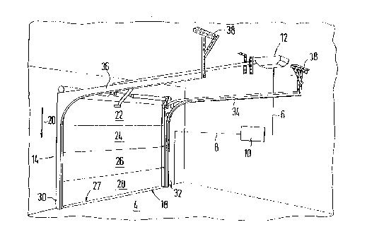
A garage door 14 in the shape of a sectional door is
illustrated in the drawings. The garage door 14 consists of a
plurality of plates 22, 24, 26, 28, guided in vertically oriented -
rails 30 and 32, which extend parallel to each other and adjoin
rails 34 and 36, also extending parallel to each other, but
disposed horizontally. The rails 34 and 36 are mounted on the
ceiling of the garage with fastening means 38. The main closing
edge 27 of the door 14, which can be moved back and forth in the
direction of the two-headed arrow 20, supports a sensor 18, which
is connected with the safety device 10 via a line 8. The safety
device 10 itself is connected with a drive device 12 of the door
via a line 6.
The safety device 10 is used to control the movement
sequence of the door 14, which cooperates with the drive device 12
with selectable operation loads, as well as with means through
--3--

a3~
which the drive means 12 are switched off within a specified
period of time in case a preselected operational load has been
exceeded. The safety device 10 which, for example, can be
fastened on a wall of the garage, can be operationally connected
with the sensor 18 and the drive device 12. The sensor 18 is
designed in such a way that it can be placed in operational
contact with obstacles crossing the movement path of the door 14,
that in such a case it emits a signal to the safety device 10 and
in this way causes the direction of movement of the door 14 to be
changed if its movement has not been interrupted within a specific
period of time after the emission of the signal. The operational
position of the door 14 is illustrated in the drawings. In the
position of rest, the plates 20 to 28 are supported by the guide
rails 34 and 36. If now the safety device is activated, the
plates 20 to 28 first move in a horizontal direction and then in
the vertical direction until they have assumed the position
illustrated in the drawings. In this case the speed of movement
of the plates depends on their position. Now, if there is an
obstacle between the ground 4 and the lowest plate 28, the sensor
18, disposed in the area of the main closing edge 27 of the door
14, is brought into operational contact with the obstacle. This
has the result that the pressure changes inside the sensor, which
has the shape of a resiliently deformable body extending along the
main closing edge 27 and is filled with gas or a liquid. The
pressure wave is converted into electrical pulses in a converter
of mechanical pulses. From there, the signal reaches the safety
devic~ 10 via the line 8, which results in the time measuring unit
being switched on, which measures the time within which the set
operational load of the drive device 12 is exceeded. With
deformable obstacles, the operational load is exceeded later than
with non-deformable obstacles, so that the drive device is
reversed and the plates of the door move upward in the vertical

2ll~a3~
direction. The sensitivity of the sensors can preferably be
increased by designing them of a larger size. In this case the
sensor is at the same time embodied as a damping body, the
compression section of which can be of several centimeters'
length, measured in the direction of movement of the plates.
The advantages which can be attained by means of the
invention consist particularly in that it is possible to achieve
with rather simple means that the movement path of the door is not
only interrupted, but also reversed, so that a situation in which
the obstacle is crunched cannot arise. In addition, the safety
device (control device) is designed such that it is connected to a
warning device which signals when the sensor is out of action. In
this case, the signal of the drive device which indicates that the
operational load of the drive device has beqn exceeded and that
the sensor is out of action reaches the control device first. The
sequence of the incoming signals, namely the one from the sensor
and the one from the drive device, also provides the information
whether the control device operates correctly. If this is not the
case, the door can be operated by means of a dead-man switch.
..

Representative Drawing
A single figure which represents the drawing illustrating the invention.
Administrative Status

2024-08-01:As part of the Next Generation Patents (NGP) transition, the Canadian Patents Database (CPD) now contains a more detailed Event History, which replicates the Event Log of our new back-office solution.

Please note that "Inactive:" events refers to events no longer in use in our new back-office solution.

For a clearer understanding of the status of the application/patent presented on this page, the site Disclaimer , as well as the definitions for Patent , Event History , Maintenance Fee  and Payment History  should be consulted.

Event History

Description Date
Inactive: IPC deactivated 2016-03-12
Inactive: IPC assigned 2016-02-10
Inactive: First IPC assigned 2016-02-10
Inactive: IPC assigned 2016-02-10
Inactive: IPC expired 2015-01-01
Application Not Reinstated by Deadline 2000-05-23
Time Limit for Reversal Expired 2000-05-23
Inactive: Abandon-RFE+Late fee unpaid-Correspondence sent 1999-05-25
Deemed Abandoned - Failure to Respond to Maintenance Fee Notice 1999-05-25
Application Published (Open to Public Inspection) 1992-12-10

Abandonment History

Abandonment Date Reason Reinstatement Date
1999-05-25

Maintenance Fee

The last payment was received on 1998-05-19

Note : If the full payment has not been received on or before the date indicated, a further fee may be required which may be one of the following

  • the reinstatement fee;
  • the late payment fee; or
  • additional fee to reverse deemed expiry.

Patent fees are adjusted on the 1st of January every year. The amounts above are the current amounts if received by December 31 of the current year.
Please refer to the CIPO Patent Fees web page to see all current fee amounts.

Fee History

Fee Type Anniversary Year Due Date Paid Date
MF (application, 6th anniv.) - small 06 1998-05-25 1998-05-19
Owners on Record

Note: Records showing the ownership history in alphabetical order.

Current Owners on Record
FRANK-UWE SOMMER
Past Owners on Record
None
Past Owners that do not appear in the "Owners on Record" listing will appear in other documentation within the application.
Documents

To view selected files, please enter reCAPTCHA code :


To view images, click a link in the Document Description column. To download the documents, select one or more checkboxes in the first column and then click the "Download Selected in PDF format (Zip Archive)" or the "Download Selected as Single PDF" button.

List of published and non-published patent-specific documents on the CPD .

If you have any difficulty accessing content, you can call the Client Service Centre at 1-866-997-1936 or send them an e-mail at CIPO Client Service Centre.


Document
Description 
Date
(yyyy-mm-dd) 
Number of pages   Size of Image (KB) 
Abstract 1992-12-09 1 26
Drawings 1992-12-09 1 25
Claims 1992-12-09 2 69
Descriptions 1992-12-09 5 223
Representative drawing 1999-10-06 1 14
Reminder - Request for Examination 1999-01-25 1 116
Courtesy - Abandonment Letter (Maintenance Fee) 1999-06-21 1 186
Courtesy - Abandonment Letter (Request for Examination) 1999-07-05 1 173
Fees 1997-04-14 1 66
Fees 1996-05-07 1 57
Fees 1993-11-24 1 40
Fees 1995-04-19 1 56
International preliminary examination report 1993-11-24 30 598