Some of the information on this Web page has been provided by external sources. The Government of Canada is not responsible for the accuracy, reliability or currency of the information supplied by external sources. Users wishing to rely upon this information should consult directly with the source of the information. Content provided by external sources is not subject to official languages, privacy and accessibility requirements.
Any discrepancies in the text and image of the Claims and Abstract are due to differing posting times. Text of the Claims and Abstract are posted:
| (12) Patent: | (11) CA 2110082 |
|---|---|
| (54) English Title: | WINDOW OPERATOR |
| (54) French Title: | DISPOSITIF DE MANOEUVRE DE FENETRE |
| Status: | Expired and beyond the Period of Reversal |
| (51) International Patent Classification (IPC): |
|
|---|---|
| (72) Inventors : |
|
| (73) Owners : |
|
| (71) Applicants : | |
| (74) Agent: | FINLAYSON & SINGLEHURST |
| (74) Associate agent: | |
| (45) Issued: | 1998-11-24 |
| (22) Filed Date: | 1993-11-26 |
| (41) Open to Public Inspection: | 1995-01-21 |
| Examination requested: | 1995-05-09 |
| Availability of licence: | N/A |
| Dedicated to the Public: | N/A |
| (25) Language of filing: | English |
| Patent Cooperation Treaty (PCT): | No |
|---|
| (30) Application Priority Data: | ||||||
|---|---|---|---|---|---|---|
|
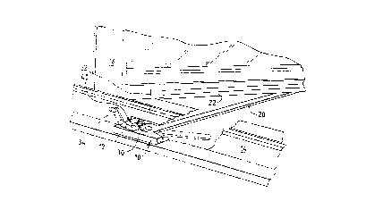
An operator for controlling movement of a window sash relative to a
window frame, including a drive gear pivotable about a central substantially
perpendicular to one side of the window frame and drivably linked to move the sash,
a connector defining first and second pivot axes intersecting at a point and rotatable
around the intersection point, a worm pivotable about an axis substantially perpendicular
to the central axis and drivably engaging a portion of the drive gear by a
helical thread having variable height peaks lying in an annular orientation substantially
conforming to the annular orientation of the drive gear portion, and a drive
input shaft rotatable about a shaft axis intersecting the worm axis at an angle. The
worm, connector and drive shaft are secured whereby the connector is pivotable
relative to the worm about the first pivot axis and the connector is pivotable relative
to the drive shaft about the second pivot axis. The worm includes a forked end
received in an annular slot defined about the connector and the shaft includes aforked end received in a second annular slot defined about the connector, with both
of the slots being centered on the intersection point and intersecting one another at
substantially right angles.
Cette invention concerne une commande de manoeuvre d'un châssis par rapport à un cadre de fenêtre, qui comprend un secteur denté pivotant autour d'un axe sensiblement perpendiculaire à l'appui de fenêtre pour déplacer le châssis au moyen d'une bielle dont il est solidaire, un connecteur définissant un premier et un second axes de pivotement sécants et tournant autour du point d'intersection desdits axes, une vis sans fin à filetage hélicoïdal et filets de hauteurs variées tournant autour d'un axe sensiblement perpendiculaire à l'axe du secteur denté et en prise avec la denture du celui-ci, le profil des filets de la vis épousant sensiblement le profil des entredents du secteur denté, un arbre d'entraînement tournant autour d'un axe qui coupe l'axe de rotation de la vis sans fin selon un angle d'inclinaison donné. La vis sans fin, le connecteur et l'arbre d'entraînement sont assemblés de façon que le connecteur puisse pivoter par rapport à la vis sans fin autour d'un premier axe de pivotement et par rapport à l'arbre d'entraînement autour d'un second axe de pivotement. La vis sans fin se termine à un bout par une chape qui se loge dans une rainure annulaire du connecteur; l'arbre d'entraînement se termine également par une chape qui se loge dans une autre rainure annulaire du connecteur. Les deux rainures annulaire ont pour centre le point d'intersection susmentionné et elles se coupent sensiblement à angle droit.
Note: Claims are shown in the official language in which they were submitted.
Note: Descriptions are shown in the official language in which they were submitted.
2024-08-01:As part of the Next Generation Patents (NGP) transition, the Canadian Patents Database (CPD) now contains a more detailed Event History, which replicates the Event Log of our new back-office solution.
Please note that "Inactive:" events refers to events no longer in use in our new back-office solution.
For a clearer understanding of the status of the application/patent presented on this page, the site Disclaimer , as well as the definitions for Patent , Event History , Maintenance Fee and Payment History should be consulted.
| Description | Date |
|---|---|
| Time Limit for Reversal Expired | 2012-11-26 |
| Letter Sent | 2011-11-28 |
| Grant by Issuance | 1998-11-24 |
| Inactive: Delete abandonment | 1998-09-10 |
| Deemed Abandoned - Conditions for Grant Determined Not Compliant | 1998-06-15 |
| Inactive: Final fee received | 1998-06-12 |
| Pre-grant | 1998-06-12 |
| Notice of Allowance is Issued | 1997-12-15 |
| Notice of Allowance is Issued | 1997-12-15 |
| Letter Sent | 1997-12-15 |
| Inactive: Status info is complete as of Log entry date | 1997-12-09 |
| Inactive: Application prosecuted on TS as of Log entry date | 1997-12-09 |
| Inactive: IPC removed | 1997-12-08 |
| Inactive: First IPC assigned | 1997-12-08 |
| Inactive: IPC assigned | 1997-12-08 |
| Inactive: Approved for allowance (AFA) | 1997-11-17 |
| Request for Examination Requirements Determined Compliant | 1995-05-09 |
| All Requirements for Examination Determined Compliant | 1995-05-09 |
| Application Published (Open to Public Inspection) | 1995-01-21 |
| Abandonment Date | Reason | Reinstatement Date |
|---|---|---|
| 1998-06-15 |
The last payment was received on
Note : If the full payment has not been received on or before the date indicated, a further fee may be required which may be one of the following
Please refer to the CIPO Patent Fees web page to see all current fee amounts.
| Fee Type | Anniversary Year | Due Date | Paid Date |
|---|---|---|---|
| MF (application, 4th anniv.) - standard | 04 | 1997-11-26 | 1997-11-12 |
| Final fee - standard | 1998-06-12 | ||
| MF (patent, 5th anniv.) - standard | 1998-11-26 | 1998-11-16 | |
| MF (patent, 6th anniv.) - standard | 1999-11-26 | 1999-11-03 | |
| MF (patent, 7th anniv.) - standard | 2000-11-27 | 2000-11-02 | |
| MF (patent, 8th anniv.) - standard | 2001-11-26 | 2001-11-01 | |
| MF (patent, 9th anniv.) - standard | 2002-11-26 | 2002-10-31 | |
| MF (patent, 10th anniv.) - standard | 2003-11-26 | 2003-11-03 | |
| MF (patent, 11th anniv.) - standard | 2004-11-26 | 2004-11-18 | |
| MF (patent, 12th anniv.) - standard | 2005-11-28 | 2005-10-06 | |
| MF (patent, 13th anniv.) - standard | 2006-11-27 | 2006-10-25 | |
| MF (patent, 14th anniv.) - standard | 2007-11-26 | 2007-11-13 | |
| MF (patent, 15th anniv.) - standard | 2008-11-26 | 2008-11-06 | |
| MF (patent, 16th anniv.) - standard | 2009-11-26 | 2009-10-30 | |
| MF (patent, 17th anniv.) - standard | 2010-11-26 | 2010-11-01 | |
| MF (application, 2nd anniv.) - standard | 02 | 1995-11-27 |
Note: Records showing the ownership history in alphabetical order.
| Current Owners on Record |
|---|
| TRUTH HARDWARE CORPORATION |
| Past Owners on Record |
|---|
| STEPHEN M. PILTINGSRUD |

