Language selection

Search

Patent 2110136 Summary

Third-party information liability

Some of the information on this Web page has been provided by external sources. The Government of Canada is not responsible for the accuracy, reliability or currency of the information supplied by external sources. Users wishing to rely upon this information should consult directly with the source of the information. Content provided by external sources is not subject to official languages, privacy and accessibility requirements.

Claims and Abstract availability

Any discrepancies in the text and image of the Claims and Abstract are due to differing posting times. Text of the Claims and Abstract are posted:

  • At the time the application is open to public inspection;
  • At the time of issue of the patent (grant).
(12) Patent Application: (11) CA 2110136
(54) English Title: CANTILEVERED SUPPORT SYSTEM FOR MOUNTING EXTRA SEATS AND/OR PARCEL CARRIERS TO A BICYCLE FRAME
(54) French Title: SUPPORT EN PORTE-A-FAUX POUR LE MONTAGE DE SIEGES SUPPLEMENTAIRES OU DE PORTE-BAGAGE SUR UN CADRE DE BICYCLETTE
Status: Deemed Abandoned and Beyond the Period of Reinstatement - Pending Response to Notice of Disregarded Communication
Bibliographic Data
Abstracts

English Abstract


A two member support system that attaches with only two bolts and two straps
to most bicycle frames. The members run parallel to the left and right side of the
top of the bicycle frame and cantilever to the front over the front wheel and to the
rear over the rear wheel. This support system creates three areas, front, center and
rear, in which varying configurations of extra seats and/or parcel carriers can be
mounted.


Claims

Note: Claims are shown in the official language in which they were submitted.

THE EMBODIMENTS OF THE INVENTION, IN WHICH AN
EXCLUSIVE PROPERTY OR PRIVILEGE IS CLAIMED, ARE
DEFINED AS FOLLOWS:
1. A "CANTILEVERED SUPPORT SYSTEM FOR MOUNTING EXTRA
SEATS AND/OR PARCEL CARRIERS TO A BICYCLE FRAME",
comprising two support members running parallel to the top left and right sides
of the bicycle frame and cantilevered to the front over the front wheel and to
the rear over the rear wheel.
2. A "CANTILEVERED SUPPORT SYSTEM FOR MOUNTING EXTRA
SEATS AND/OR PARCEL CARRIERS TO A BICYCLE FRAME", as
claimed in Claim 1, that provides three areas, front, center and rear, in which
varying configurations of extra seats and/or parcel carriers can be mounted.

Description

Note: Descriptions are shown in the official language in which they were submitted.


110136
CANTILEVERED SUPPORT SYSTEM FOR MOUNTING EXTRA
SEATS AND/OR PARCEL CARRIERS TO A BICYCLE FRAME
The present invention relates to a support system that easily attaches to most
bicycle frames and provides a base for mounting additional seats and/or parcel
carriers.
There are several problems with known ways of attaching additional seats
and/or parcel carriers to a bicycle frame. Front parcel carriers which attach to the
front forks of a bicycle move with the steering assembly and this movement
reles with the steering and balance. The method for ~tt~hin~ a parcel carrier
or extra seat to one size of bicycle frame will often not work for a smaller or larger
frame. Most add on parcel carriers or seats are not as strong as the frame they are
0 mounted on.
The present invention is a simple two member support system that attaches
easily, with only two bolts and straps, to varying sizes and styles of bicycle
frames. When a front parcel carrier is mounted on this support system, the carrier
remains detached from the steering assembly and thus does not interfere with
steering balance. This support system is as strong as the bicycle frame it is
attached to.
The invention, as exemplified by a pler~lled embodiment, is described with
reference to the drawings in which:
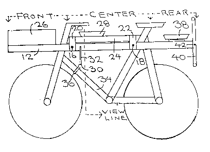
Figure 1 is a side view of the support system mounted to a bicycle frame. A
20 parcel carrier and two extra seats have been mounted.
Figure 2 is a top view of the support system with the parcel carrier and extra
seats removed.
Figure 3 is a rear view of the center zone seat and foot rests taken from the
view line shown in Figure 1.
Figure 4 is a rear view of the rear seat showing hand grips and foot rests.

~ Z~ 0136
Ref~rrin~ to the drawings, the embodiment of the invention shown, support
members 12 and 14 are held tightly against the left and right side of the bicycle
frame by bolts 16 and 18. To facilitate att~chin~ the support members to varyingstyles and sizes of bicycles, there should be several adjacent holes, in each
member for the bolts. To prevent the support members from slipping dowllw~rds
under load conditions, straps 20 and 22 pass over the top of the bicycle frame'scrossbar 24 and are fastened to support members 12 and 14 with bolts 16 and 18.
There are three zones for mounting extra seats and/or parcel carriers. The frontzone is suitable for a parcel carrier 26 but is not suitable for an extra seat. The
0 center zone is suitable for an extra seat for a child who is old enough to balance
and to hold on to the handlebars. A standard bicycle seat 28 can be attached to the
support members 12 and 14 with hose clamps. The foot rest 30 is held to bicycle
frame member 34 with a u-bolt 36 and cable 32 which is secured taut to the
support members 12 and 14.
The rear zone is suitable for mounting either a parcel carrier or several types of
seats. For a small child a regular car seat with restraint system can be mountedfacing the front of the bicycle. For a larger child, who is able to balance and hold
on by themselves, a standard bicycle seat 38 can be mounted, facing backwards, to
support members 12 and 14 using hose clamps. The hand grips and footrest
20 assembly 40 is bolted between support members 12 and 14 with bolt 42.

Representative Drawing
A single figure which represents the drawing illustrating the invention.
Administrative Status

2024-08-01:As part of the Next Generation Patents (NGP) transition, the Canadian Patents Database (CPD) now contains a more detailed Event History, which replicates the Event Log of our new back-office solution.

Please note that "Inactive:" events refers to events no longer in use in our new back-office solution.

For a clearer understanding of the status of the application/patent presented on this page, the site Disclaimer , as well as the definitions for Patent , Event History , Maintenance Fee  and Payment History  should be consulted.

Event History

Description Date
Inactive: IPC deactivated 2021-11-13
Inactive: IPC assigned 2020-08-21
Inactive: IPC expired 2020-01-01
Application Not Reinstated by Deadline 1996-05-26
Time Limit for Reversal Expired 1996-05-26
Inactive: Adhoc Request Documented 1995-11-27
Deemed Abandoned - Failure to Respond to Maintenance Fee Notice 1995-11-27
Application Published (Open to Public Inspection) 1995-05-27

Abandonment History

Abandonment Date Reason Reinstatement Date
1995-11-27
Owners on Record

Note: Records showing the ownership history in alphabetical order.

Current Owners on Record
DAVID WANKE
Past Owners on Record
None
Past Owners that do not appear in the "Owners on Record" listing will appear in other documentation within the application.
Documents

To view selected files, please enter reCAPTCHA code :


To view images, click a link in the Document Description column. To download the documents, select one or more checkboxes in the first column and then click the "Download Selected in PDF format (Zip Archive)" or the "Download Selected as Single PDF" button.

List of published and non-published patent-specific documents on the CPD .

If you have any difficulty accessing content, you can call the Client Service Centre at 1-866-997-1936 or send them an e-mail at CIPO Client Service Centre.


Document
Description 
Date
(yyyy-mm-dd) 
Number of pages   Size of Image (KB) 
Abstract 1995-05-27 1 12
Description 1995-05-27 2 83
Cover Page 1995-07-14 1 16
Drawings 1995-05-27 1 28
Claims 1995-05-27 1 21
Representative drawing 1998-06-30 1 12