Note: Descriptions are shown in the official language in which they were submitted.
2110171
`_
S~ lCATION
TITLE OF THE IN~E~TION
COMPOSITION FOR HIGH PRESSUR~ GASTING SLIP. HIGH l'RESSURE
CASTIN~ SLIP AND METHO~ OF PREPA~IN~ T~ COMPO~ITIO~ AN~
SLIP
DETAILED DESCRIPTIO~' OF THE INYE~TION
Fleld o~ the In~ention
The present invention relates to a composition f'or high
pressure casting slip, a high pressure castlng slip pre-
pared bY the compositlon and a method o~ preparing the
co~positlon and sltp.
Prior Art
In Japanese Patent Lald-open Publlc&tion ~. 4-48604,
there ~s disclosed a method of molding ~ ceramic article by
slip-castlng, wherein a suspension of castlng slip under
pressure is poured into a porou~ mold so that a dif~erence
in pressure between the interlor and exterlor of the mold
causes water of the slip to discharge through the porous
walls o~ the mold and that ~olid m~tter i~ ~he slip is
deposited on the lnternal walls of the mo~d and formed in a
desired shape. The ~olding ~ethod is use~ul to form a
ceramic article of complicated shape, and the cost of
equipment ~or the ~olding method ls inexpensive. For this
_ 2110171
reason, hereto~re, the motdln~ method has been adapted to
~orm a mold body for tableware. flower vases, household
potterys ~n~ the llke. In the molding method. the casting
sllp l.s prepared by first starting powder in the form of
one or plural powder raw materlals selected ~rom the group
consisting of fledspathic m~terial, silicate materi~l,
alumina material. porcelain sto~e, roseki ~nd the llke and
second starting powder in the form o~ one or p~ural powder
raw materi~ls selected ~rom the group consist~ng of Galrome
silica ~and, kaolin, ~lbushi clay, burned clay and the
llke. The ~lrst starting powder is u~ed to form the frame
of the mold body. ~nd the second starting powder is used to
~orm the ~rame of the mold body and adapted as a plas~c
a~ent.
The f~rst ~nd ~econd startlrlg powder ls cas~ with w~er
lnto a ball mill and ground in a wet condition. Simultane-
ousl~, the starting powder i~ mixed unl~ormly ln the ball
mlll. To enh~nce the e~fi.clency oE grinding and.mlxing ln
a wet condltion, it ls required to apply ~n appropriate
viscosity to the mlxture in ~he ball mill. If the viscosi-
ty of the mlxture is high in exce~s. 1~ wlll become impos-
sible to grind and mix the starting powder. If the viscos-
ltY o~ the mixture ls low in exces~, the grinding efficien-
cy ~ill noticeably decrease. In ~he grinding and mixing
proces6, it i6 pre~erable that an amount of water in the
mixture i ~, ln general, in a range of 45 to 55% by weight .
2110171
To e~ect optimal fluidity of the ~lip during the casting
process, it is preferable that the water content of the slip
is in a range o~ 30 to 40% ~y weight. In the c~se that the
slip with such a water content is used for ~he slip cast-
ing, the water content of the finished mold body becomes
about 20% by weight.
PROBLEM TG BE SOLYED
In application o~ the ~lip casting in 1ndustry, lt ls
required to make Ihe wor~n~ t~e of sliP casting as short
~s possible. Accordlngly, it is requlred to shorten the
time for preparatlon of the slip and ~or slip castlng.
However, in case the efficiency of wet grlndlng and mixing
of the starting powder in the ball mill was enh~nced, the
water content of prepared 91ip would become 46-55% by
weight, ~nd the time for removlng the water ~rom the sllp
and for slip cas~ing would be prolonged to obt~in the
finished mold body with the water content of a~out 2~% by
weight.
To overcome the foregoing problem, it is desirable that
the sllp prepared by wet ~ixing ln the ball mlll is heated
to vaporize the water theref'rom ~or ad~usting the water
content of the slip in the range o~ 30-40 % by wefght for
effecting optimal ~luldlty of the slip during the ca~ting
process. This is effectlve to shorten the tlme for remo~-
ing the water from the slip during the casting process. In
- 2110171
such ~ case, however, an additional tims is re~uired for
heating the slip, and the degree of vapori~ation of the
water in the 611p may not be un~ormly controlled, result-
lng ln irregular coagulation of fine pow~er partlcles ln
the slip. I~ the sllp was used for the slip casting,
su~icient s~rength of the mold body would not be obtained.
As one of other methods for shortening the ca~tin~
time, it has been proposed to carry out the sllp casting
under a hlgh pressure as dlsclosed ln the Laid-open Publi-
cation. HoweYer, even lf only the casting pressur~ was
increased, the casting time would not be adequately short-
ened.
It is, there~ore, ~n obJect o~ the present lnventlon to
provide "slip" the water content of which can be easily
~dju~ted to a mini~um value for e~ecting optimum fluidity
o~ the slip during the c~sting process thereby to remove
the water from the "81ip" under high castlng pressure in a
short time for shortening the casting time.
MEANS FOR SOLVING THE PROBLEM
The present in-.rention i s co~lcerned wit~ a composltlon
for high pressure castlng slip. ~ hlgh pressure casting
911p and a method o~ preparing the composit~on and slip.
The ~omposition ~or high Pressure casting slip according to
the present lnventlon essentlally consists of first ~t~rt-
2110171
-
ing powder forming the ~rame of a mold body and second
starting powder forming the ~rame of the mold body and
actin~ as a Plastlc agent, wherein both the startin~ powder
is uniformly mixed in a dry conditlon.
In the composition ~or high pressure c~stlng slip, it
ls pre~erable that the average particle diameter of the
second starting powder is equal to or smaller than that of
the flrst starting powder, and it is also pre~erable that
the whole second starting powder or a portlon of the same
is in the ~orm of secondary parti~les formed by coagula~ion
of primary p~rticles andJor that the respectlve ~vera~e
pArticle diameter of the starting powder is in a range of
1-5 ~m. In the composltion for casting slip, it t s fur-
ther pre~erable thEIt the ilrs~ ~tarting powder ~s ln the
form of one or plural powder raw materials selec~ed from
the group consisting of fledsp~thic material, silicate
material, alu~ina material, porcelain stone and roseki, in
the form of one or plural mineral composi te powder raw
materials selected ~rom the group consistin~ of quartz,
orthoclase, alblte, anorthite, sericite and corundum or in
the ~orm o~ one or plural chemical composite powder raw
mRterials selected from ~he ~roup consisting of Al203;
SiO2; Al203 and SiO2; K~O, Al203 and SiO2: Na20, Al203 and
S102; and CaO, Al203 and SiOz. It is also pre-~erable that
the second starting powder is in the ~orm of one or plural
powder raw materials selec~ed from the ~roup consisting of
2110171
Galrome clay, kaolin, Klbushi clay and burned clay or in
the ~orm o~ one or plural mineral co~posLte powder raw
materi~ls selected from the group conslsting of kaolinlte,
met~halloysite, pyrophylllte, montmorillonite, halloysite
and dlckite. In additlon, the ~ledspathic material in-
cludes rocks essentially con~lsting of orthoclase, albite
or anorthite, saba stone and the l.ike. The alumina materi-
al includes bauxite, cor~ndum bauxite and the llke.
According to the preserlt lnventlon, the high pressure
cas~ing slip ls prepared by the fore~oing composition
dispersed in an a~ount of water in such a manner that ~he
water content of the slip becomes 25-40% by weight.
Accordin~ to the present inventlon, the method of
preparing the composition for hlgh pressure casting slip is
characterlzed in that the second startlng powder is pre-
pared by drylng and grlndln~ the second powder raw material
or the mlneral composite powder raw mater$al and that the
second starting powder ls m~xed wlth the rirst starting
powder in a dry condi~1On to o~tain the composltlon ~or
high pressure cast~ng 611p. In the preparation method, the
second po~der raw material or the mlnera~ composite powder
raw material is dried and ground at 120-400 C. Alterna-
tlvely, the second powder raw material or the mlneral
composlte powder raw materl~l ls ground a~ter dried ~t 120-
400 C. In the preparation method, it ls pre~erable that
2110171
the ~irst st~rt$ng powder i6 prepared by dry grlnding the
~irst powder raw material, the mlneral composite powd~r raw
materlal or the che~ical composi.te powder raw material or
that the ~irst powder raw materlal, the mlneral composite
powder raw material or the chem~cal composite powder raw
material and the second powder raw materinl or the mlneral
composite powder raw material are ground at the sa~e time
in a dry condltlon. Alternatively, it ls desirable that
the flrst starting powder is prepared by wet grinding the
~lrst powder raw materi~l, the mlneral composite powder raw
materlal or the chemical composite powder raw material.
Accordln~ to the present invention, the method o~
prepAring the 911p i8 characterized in that the composltion
prep~red by the ~oregoin~ method ls added with a predeter-
mined amount o~ water to obtain the sllp of a predetermined
water ~ontent or that the composition Prepared by the
foregolng method is mlxed with diluted slip of the same
composltlon to obtaln the sliP of a prede-termir~ed water
content.
USEFUL RESULTS OF THE INVENTIO.~
~ or prepar~ion ~f high pressure casting slip. lt has
been under~tood that powder raw material can be efficiently
and uni~ormly mlxed by wet grinding in a grlnding machine
such a ball mill.. It has been, however, ~ound that per-
f~rmance of a ~rinding machine and a mixing machlne w~s
- _ 2110171
enhanced in recent ye~rs to eff~clently grlnd the r~w
materials of the first and secorld starting powder, the
m~neral composition, the chemical composition or the like
in a dry condltlon and to uniformly mix the ground powder
in a simple manner. The present invention wns ~ade by
recognition o~ *he above fact.
Accordingly, the co~position for high pressure casting
slip can be easlly prepared by grinding o~ at least the
second powder raw m~terial and the mineral composite powder
raw material in a dry condition and mixin~ the second
startlng powder wlth the first ~tartlng powder ln a dry
condition. In prep~ration of the high pressure casting
sllp uslng the comp~lticn, an a~ount o~ water added to the
co~position can be approprlately ad~usted in ~ short time.
Thus, it is able to prep~re the ~lip with a mlnlmum water
content cap~ble of ef~ecting op~imal fluidlty for the slip
casting. Namely, the water content oP the slip can ~e
easily adJusted ln a range of 2D-40% by weight in ~ short
time. As a result, it is able to minimize the amo~nt of
water to be absorbed in the slip casting for produclng ~
mold body wlth water content of about 20% by weight. This
is effective to shortent the slip casting time.
In comparison with slip the water ccntent o~ which is
minimized by vaporization of water for cffecting optimal
flu~dlty for sl~p castlng, it is able to significantly
- 2110171
shorten the preparation tlme of the slip and to unlform the
content o~ the slip ~or enhancing strength of the mold body.
In the compo~it~on ~or high pressure casting slip
accordlng to the present lnvention, the average particle
diameter o~ the second starting powder is de~er~ined to be
equal to or less than that o~ the rlrst starting powder,
and a portlon of the second starting powder or the whole
second starting powder ls ln the form of secondary parti-
cles formed by coagulation of' primary partlcles of the
powder. In the sllp prepared bY the CompGSltion, the
particle diameter of the second starting powder ls ad~usted
to be larger th~n the prlmary particle~ of the same. This
ls effective to restrain clog of the porous walls of the
mold durlng the sllp castlng ~nd to ensure water permeabil-
ity o~ ~olid matter deposited on the interna' walls of the
mold. As a result, lt is able to discharge the water from
the slip in a short time ~or producing the mold body with
the predetermlned water content. This is useful to shorten
the working time for slip castin~.
The eomposition for casting slip can be easily prepared
by drying and grlndlng the second powder raw material or
the mlneral composite powder raw material at a temperature
of 120-140 C or grlnding the second powder raw material or
the mineral composite powder raw material af~er drying at a
tempera~ure of 120-140 C. The prlmary yarticles of the
2110171
second starting powder are in the form of fine particles
the surfaces of which are covered with a water membrane of
a predetermined thickness. When the second powder raw
material or the mineral composite powder raw material is
heated, the water on the particle surfaces is removed to
decrease the thickness of the water membrane so that the
primary particles of the powder raw material are coagulated
into secondary particles the diameter of which is enlarged.
If the heating temperature of the powder raw material is
less than 120C, the amount of water removed from the
particle surfaces will decrease. In this case, the second
starting powder is returned to the previous condition
before heating when dispersed in water, and the particles
of the second starting powder in the slip are returned to
the same condition as the primary particles. If the
heating temperature of the powder raw material is more than
400C, the amount of water removed from the particle
surfaces will increase. In this case, the plasticity of
the second starting powder will be deteriorated to damage
the property of the second starting powder.
BRIEF DESCRIPTION OF THE DRAWINGS
The present invention will be explained in more detail
with reference to the appended drawings, in which:
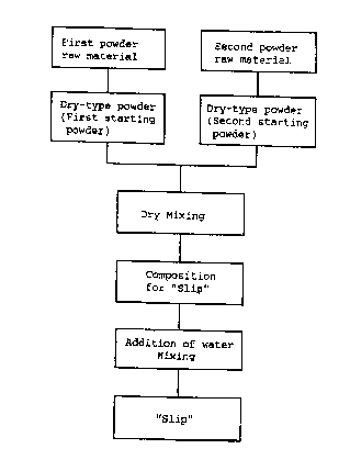
Fig. 1 is a view showing a preparation process of
"slip" according to the present invention,
Fig. 2 is a vertical sectional view of a grinding
machine suitable for grinding a second powder raw material;
-- 10 --
2110171
-
Fig. 3 is a vertical sectional view schematically
illustrating a high pressure slip casting device suitable
for molding the "slip" according to the present invention;
Fig. 4 is a graph showing a relationship between
the water content of the "slip" and the slip casting time;
Fig. 5 is a view illustrating variation of the slip
casting characteristic of the "slip" in relation to the
heating temperature of the second powder raw material;
Fig. 6 is a graph showing a relationship between
the drying temperature of the second powder raw material
and the slip casting time; and
Fig. 7 is a graph showing a relationship between
the casting pressure and the slip casting time.
DETAILED DESCRIPTION OF THE INVENTION
Process for preparation of "slip"
A process for preparation of "slip" according to
the present invention is illustrated in Fig. 1. As shown
in Fig. 1, one or plural powder raw materials selected
from the group consisting of feldspathic material, silicate
- lOa -
2110171
m~terial, alu~in~ m~terlal, porcelaln stone and roseki is
used for preparation of ~irst startin~ powder, and one or
plural powder ra~ meterials ~elected from the group con-
sisting Or Gairome clay. kaolin, Klbushi clay and burned
clay i9 used for preparation of second s~arting powder. In
the present inventlon, the raw materlal for the ~irst
starting powder may be replaced wit~ one or plural mineral
composite powder raw materi~Ls ~elected from the group
consigting of quartz, orthoclase, albite, ~northlte, seri-
cite and corundum or one or plural chemical compos~e
powder raw materlals seiected from the group consisting of
Al203; SiV2; Al203 and SiO2; K20, A1~03 and SlO2i Na20,
Al203 and SiO2: and C~0, A1203 and SiO2. The raw material
of the second startin~ powder may be replaced with one or
plural mlneral composlte powder raw materials selec*ed from
the group consisting o~ k~olinite. metahalloysite, pyro-
phyllite, mont~orillonite, hall~ysite and d~ckite.
The ~irst powder raw material is ground in a dry condl-
tion using a roller mlll, a ~et mlll, a medium ~irrlng
mill or the like to produce ~irst starting powder in the
~orm o~ fine powder of 1-8 ~m ln AYerage particle dlame-
ter. Since the second powder r~w material contains water,
it is dried by heat wind and ground ln a dry condition
using ~ grindlng machlne to produce second startlng powder
In the form o~ ~ine powder of 1-5 ~m in a~erage p~rticle
dI~meter. In thls case, the par~icle di~meter of the
21101~1
second st~rting powder ls determined to be equal to or
smaller than that o~ the ~irst starting powder. In addi-
tion, it ls pre~erable that the heat drying temperature o~
the second starting powder is ad~usted in a range o~ lZO-
400 'C. In Fig. 2 there ls illustrated a grindin~ machine
suitable ~or grinding the æecond star~ing powder.
If the heating temperature of' the second sturting
powder is determined to be lower than 120 C, ~n amount uf
water removed ~rom the sur~ace of partlcles will decrease.
~hen dispersed into water, the second startln~ powder ls
returned to the previous condition before the heating
process, and the particle diameter of the second startlng
powder ln sllp" becomes the same as that of the primarY
particle ~hereof before the heating process. IY the heat-
ing temperature of the second starting powder exceeds
400 C. an amount of water removed ~rom the surface of
particles will gradually incr~ase. This deteriorates
plasticity of the second starting powder.
The ~irst and second startlng powder prepared by the
~oregoln~ processes Is cast at a predetermined ratio into a
dry-type mixing machine and uni~orml~ mixed ln ~ dry condi-
tion to prepare a composition for "slip". In this case, it
is preferable that a mixing machine equipped wit.h a hlgh
speed lmpeller is Adapted as the dry-ty~e mlxlng machlne.
For example, the co~po~ition for "sllp'` is prepared by
-
2110171
mlxlng the ~irst startLng pcwder of 95-60% by weight with
the second staring powder of 5-40S by weight.
For preparation o~ "slip" accordlng to the present
invention, the composltion ~s adde~ with a predetermlned
amou~lt o~ water or diluted slip the water content o~ which
is more than that of ~he "slip" used for casting. In
necessity, the composition is added with peptization agent,
coagulation agent or the like and is unl~ormly mlxed thère-
with. In thls case, it ls preferable that ~he amount of
water added to the compositlon ls determined in accordance
wlth the a~ount o~ the second startlng powder to be as
small ~s poss~blc ln ~ range for effectlng opti~al ~luldlty
of the sliP fo~ hi~h pressure casting. Preferably, the
w~ter content of the sllp is determined to be ~5-40 X by
weight. The prep~red slip is used as a raw mater1~1 for
hlgh pressure casting to ~or~ a ceramlc mold body ln a hlgh
pressure casting machine, for example, shown in F'ig. 3.
Grlndin~ Machine
As showrl in Fl~. 3. a conYentinai rvller mill lOa is
adapted to heat and grind the second starting powder con-
sisting of clay in a dry ccndition. The ro~ler mill LOa
h~ a houslng ~ody 11 formed with a grinding chamber lla,
an annular rotary table lZ mounted on the bottom of grind-
lnF chamber lla and a roller 13 mounted ror rotation within
the grlnding chamber lla to be drlven on the rotary tablc
1~
- 2110171
12. In the housin~ body lOa, the ~econd starting powder is
cast onto the r~t~ry table 12 through an upper inlet open-
ing llb o~ the housing body, dried by heat wind supplled
~rom a lower openlng llc of the housing body and ground by
the roller 13. The ground powder is blown uP by an ascend-
ing current in the housin~ body 11 and .~upplied into a
classificatlon chamber ll.d. Thu~, only fi~e powder ~f less
than a predetermlned partlcle diameter is discharged from
the classiflcation chamber l~d throu~h an outlet opening
lle of the houslng body 11, while coarse po~der o~ more
than the predetermined part~cle dlameter is returned onto
the rotary ~able 12 in the grinding chamber lla. Arranged
a~o~e the roller mill lOa is a raw material suppl~ device
lOb for castinF the second startin~ powder into the housing
body 11. The raw mater$al supply device lOb includes a
hopper 14, a screw feeder ~5, a heater 16 and a belt COIl-
veyor 17. The heater 1.6 and belt conveYer 17 are arran~ed
within a drylng ~urn~ce of the tunnel ty~e ~not shown). In
the raw material supply device 10~, the secolld star~in~
powder stored in hopper 14 is transported by the screw
feeder 15 and supplied onto the belt COIlVeyer 17. The
second starting powder on belt conveyer 17 is dried by the
he~ter 16 at 120-140 'C durln~ *ravel in the drYing fur-
nace. Thus. the second starting powder dried in a prede-
ter~ined condltlon is cast lnto the housing body 11. In
operatIon o~ the raW material supply device lOb, the hous-
Lng body ~1 may be supplied with the air at a normal tem-
2110171
-
perature through the lower openlng l~c.
High pressure casting device
In Fig. 3, there i9 schematically i~1ustrated ~ high
pressure casting device 20 which is adapted to form a
ceramic body using the "sllp" accordlng to the present
inventlon. The cAstlng devlce 21 ls malnly composed of a
casting mold Z1, a storage tank 22, a decompresslon pump 23
and a compressor 24. The casting mold 21 i9 COmp~9ed 01 a
palr of upper and lower dies 21a, 21b ~hich are made oY
porous material and ~oated wl~h a sealln~ agent. The dles
21a, 21b are mounted on a base structure 25 to be opened
Rnd closed by a clampllng m~chlne 26. The castin~ mold 21
is connected to the decompre~si.~n pump ~ and co~pressor ~4
to be made in a neFatlYe or po~l tl ve pre~sure condltlon by
selective operation thereo~.
The storage ~ank ~2 is provlded with an agitator ~2b
which ls arranged to unlformly stlr the slip 17 ~tored in
the storage tank 22. The housing b~dy 22a of stvrage tank
22 is connected ~t its bottom to the interior o~ c~sting
mold 21 and at its upper portion to the decompression pump
23 and compressor 24. The slip in ~he hGuslng body 22a is
applied at it~ upper portlon wlth a high pressure iD opera-
tion of the compressor ~4 and is depressurized by operation
of the pump 23 to remove bubbles ~here-rrom. In additlon,
the connectlng conduI~s of the pump 2~ and co~pressor 24 to
the casting mold 21 and storage tank 22 are respecti~elY
_ 21I0171
provided wlth ch~ngeover v~lves 28a, 28b which are operated
to selectively connect the pump 2~ to the c~sting mold 2L
or stor~ge tank 22 and to selectively connect the compres-
sor 24 to the casting mold 21 or storage tank 22.
In the casting device 20, the sllp 27 under high pre~-
sure (10-40 kg/cm2) in the storagc tank 22 is supplied in~o
the casting mold 21, while the lnterior of castin~ mold 21
is depressurized. In such a condition, the ca~tlng mold 21
absorbs water ~ro~ the sllp bY a di~erence in pressure
between the storage tank 22 and casting mold ~1, whereby
soll~ m~tter of the slip builds up as a deposit on the
internal wall of casting mold 21 to ~orm a mold bodY the
water content o~ whlch ls about 20~ by we~ght. Therea~ter,
the pressure in casting mold 21 is m~de positive, and the
castlng mold 21 ls opened to remove the ~old body there-
from. The mold body is dried in neces~ity and is ~ired
after ~teps of flnishing and glazing to provide a ceramic
article.
Experiment 1
In the high pressure ca~tlng devlce shown in Fig. 3,
casting experlments have been conducted ln various condl-
tions usin~ "slip" (Embodimen~s 1-16) prepared by the
compositlon according to the present inventlon ~nd "sllp"
(Comparative sample6 1-9) prepared ln a conventional man-
ner. The "slip" used in the respective em~odlments was
16
2110171
prepared by a composition prepared by dry mixing of first
starting powder consistlng of dry ground ~eldspar, silica
stone and alumlna and second starting powder consisting o~
dry ground clay. In this case. the respective average
partlcle diameter o~ the powder was determined ln a range
of 1.5-4.0 ~m, the amount of the second starting powder
relatlve to the whole amount of the composition was deter-
mined in a range of 5-40X by weight, and the water content
of the "slip" was determined in a rarlge of 25-40% by
weight. The "sllp" used in the comparati~e samples was
prepared by wet grlndlng and wet mixin~ o~ the same raw
materials ae those ln the e~bodi~ents. The average parti-
cle diameter o~ the raw materlal and the component and
water content o~ the "slip" are substantlally the same as
those o~ the "slip" used in the embodiments. Pro~lded that
the water content Or the ~lip used ln the comparstlve
samples was ad~usted by heating the "slip".
In the experiments, the slip castlng was carried out
under a castlng pressure of 30 k~/cm~ to form a clrcular
mold body of lOOmm in diameter, 20mm in thicknes~ and 20X
by weight in water content. The strength of the mold body
was measured by a three-point bendlng test. and ~he.sllp
castlng time was measured. The results of the experiments
are indicated in the following Table 1, wherein the avera~e
particle diameter D50 represents a partlcle dlameter at a
point of 50% by weight in particle size distribution of
-- 2110171
method .
Table 1
Average S~cond Water Ca8ting Strength
Test p~rticle startin9 content t~me of Hold b~dy
No, d50 ~1 ) ~ wt96 ) ( min ) ( kg/cm2 )
Emb. 1 1.5 5 284.0 32
2 1.520 339.4 35
3 1 . 5 20 39 1 1 . 1 37
4 1.540 3514.1 41
1.540 3915,8 43
6 2.5 5 Z72.3 33
7 2.5~0 3~4.0 35
- 8 2.510 374.5 35
2 . 5 40 32 7 . 8 37
2 . 5 4û 37 9 . o 40
11 3.0 5 251.~ 30
12 3 . 0 ~ 3~ 2 . 3 34
13 3 . 0 10 32 3 . 2 36
14 3 . 0 4Q 37 7. 5 4Z
4 . 0 10 24 1 . 8 35
lB 4.010 272.0 32
Com . 1 1. 6 5 30 6 . 2 Z6
2 1 . 6 20 39 1 6 . 1 3~
3 l . Q 40 39 2 2 . 8 34
.~ 5 29~.8 24
2 . 5 10 33 6 . 2 25
-
21 iO171
-continued
Test part cle stPr. ng content t~e Strength
No. d50~m) ~wt%) (m.n) (kg/c~
. ~.5 40 ~7 13.8 28
73.0 5 32 3.5 23
83.0 10 3Z 5.Q 26
93.0 40 37 11.5 27
In the ~oregoing embodiments, the slip castin~ time was
shortened since the "slip'r was prepared by the composition
in a dry condition for adJustlng the water content o~ the
slip to a mlnlmum a~ount for pro~-ldinF fluidlty required in
the slip ca~tlng. In the e~bodiments, it has been ~ouned
that the strength o~ the mold body was increased in con-
trast with the comparative samples the water content oi
wh~ch was adJusted by vaporization caused by heatin~. In
the comparative samp~es, v~porization of the water bec~mes
irregular ln t~le Gurface and interior of the 611P~ resu tlng
in varlatlon in a coagulated condition of ~ine particles o~
the powder. ~ue to varlation of the ~.ne partlcles, the
~llp casting time of the comparative samples was gre~tlY
dl~erent fro~ that o~ the embodi~ents, as shown in Table
1. Slnce the water content o~ the slip in the co~parati~e
samples was ad~usted by heating. a lo~g time was spent ~or
preparatlon of the sllp. For this point o~ ~iew, the
workinF tlme ~or the s~ip cast~n~ in the comp~rati~e ~m-
19
2110171
working ti~e ~or the slip casting in the comparative ~am-
ple~ may not be shortened.
Althou~h ln the foregoing embodlments an amount of
water was added to the composition for preparation o~ the
"slip", diluted slip may be substituted ~or the water ~or
adJusting the water content o~ the sllp.
Experlment 2
In the high pre~sure slip casting device shown ~n Flg.
3, slip casting experiments were carried out using "s~ip"
(Embodiments 1-9) prepared by the composition according to
the present invention, "slip" (Comparative samples 3 and 5)
prepared ln 8 conventio~al manncr And "91ip" (Compar~tive
samples 1, 2, 4 and 6) prepared by a compositio~ dlf~eren~
~rom the compositlon according to the present lnvention.
The "slip" used in the respective embodiments was prepared
~y a co~position prepared by dry ~ixlng of flrst starting
powder conslstlng o~ dry ground ~eldsp~r, silica st~ne and
alumina and second starting pow~er consistlng of dry ground
clay. In this case, the raw materlal of the second start-
ing powder was preliminarily hested and dried at 120-300
'C. In the comparative samples 1, 2, 4 and 6, the raw
materlal o~ the second starting powder was heated and dried
at a temperature o~t o~ 120-300 C. In the respectlve
slip, the a~erage particle diameter of the powder was
determined in a range of 1.5-4.0 ~m, the a~ount o~ the
2110171
second starting powder relative to the whole amount o~ the
composition was determined in a range of 5-40% by wei~ht,
and the water content of the slip was determine~ ln a range
of 25-40% by weight. The slip used in the comparatlve
samples 3 and ~ was prepared by wet grinding and mixlng o~
both the raw materlals. The average partlcle diameter o~
both the powder ~nd the component and water content o~ the
slip were determined to be substantiAlly the same a~ those
in the embodiment~. Provlded that the water content of the
sllp used in the comparative sampleB w~s adjusted by heat-
l ng the ~lip.
In the experiments, the 61ip casting was carried out
~nder a casting pressure o~ 20 kg/cm2 to for~ a circular
mold body of 130mm ln dlameter, 30mm in thickness and 20S
by weight in water content. The c~sting time ln the slip
castin~ was me~sured, and the results of the measurement
are llsted ln the followlng Table 2. Addltlonally, the
slip ca6ting time was measured ln relation to the respec-
tive water content of the slip prepared by the dry type
composltlon ~the heatlng temperature of the second startlng
powder: 120 C) and the sllp prepared by the wet type comp~-
sltion, and the result of the measurement is shown in Fig.
4. In this case. the conditi~n for preparatlon of the
sllp, the characteristic of the slip and the conditlon ~or
slip casting were determined as described below:
S}lp cc7mposltion: Ieldspar 30 wtX, ~ilica ~and lOwtD~."
alumlnlu~ Oxide ZO wtX, G~irome clay 40wt%
2110171
Partlcle diameter of slip: 3 ~m
Slip castlng pressure: 40 kg/cm2
Table 2
~eat Secondng water C~ting
Test dryinppowder content time
No. temP ~CC~(wt%) (wt~) ~m1n)
Emb. 1 1~0 5 29 2.4
2 200 5 30 1.4
3 300 5 30 2.3
4 120 10 29 - 2.5
200 ~0 30 1.5
6 300 10 30 2.5
7 120 40 29 2.8
8 200 40 30 1.7
9 300 40 30 2.7
Com. 1 110 5 29 3.2
2 600 5 30 4.3
3 ~on dry10 32 3.6
4 110 10 29 3.4
~ Non dry40 32 3.~
6 600 40 30 4.8
In the roregolng embodiments 1-9 where the sllp was
prepared by the composition accordin~ to the present inven-
tion, the slip casting tlme w~s shortened ~ince the water
content of the slip could be e~sily ad~usted to a ~inlmum
22
2110171
content oi the slip could be eas~ly adJusted to a minimum
amount for providing fluidlty required for the slip cast-
in~. In the embodiments, the raw materlal of the second
starting powder was heated and drie~ at a proper te~pera-
ture ~or preparatlon of the composition. As a result, the
characteristic o~ the slip ln the ca~ting process was
greatly influenced bY heatlng and drying of the ~lip, and
the slip casting time was greatly shortened in contrast
wlth the comp~rative samples for the ~ollowing re~sons.
In the case that the raw materlal o~ the second start-
ing powder was heated and dried at a te~perature of.120-300
'C, the ~lne particles o~ the sec~nd ~tartlng powder are
coagulated 90 that primary particles A shown in Fi~. 5(a)
becomes secondary Particles B of suitable si~e shown in
Fig. s(b). The secondary particles ~ ~re uniformly mlxed
with fine particles C of the flrst st~rting powder in the
sllp and retained in an appropriate particle size. Thus,
in comparlson with the.slip where the second starting powder
is present in the rorm of the prlmary partlcles, the lo~d-
ing o~ the mold for slip casting is restrained to enhance
water permeabillty o~ the solid matter deposited on the
m~ld. Thls ls e~ectlve to shorten the slip casting time.
In the case that the second starting powder was heated
and dr~e~ at a temperat~re out of the foregoln~ range, the
above-described result may not be obtained. If the heat
2110171
drying temperature ls less than 12U C, the ~econdary
particles ~ormed by heatlng and dryln~ becomes the ~rimary
partlcles when dlspersed in water during preparation of the
slip. 'l'hls reduces the e~fect ~or sh~rtening the slip
cas~lng tl~e. If the heat drylng temperature i9 more th~n
300 C, the characteristic o~ the clay is damaged to dete-
riorate the plastlcity of the slip, resu~ting in decrease
o~ the strength of the mold body.
Experiment 3
~ ed on t~e ~oregoin~ recognition, an experlment was
conducted to clari~y a relationshlp between the temperature
for heating and drylng and the slip casting time of the raw
material o~ the second startlng powder ~n the ~orm of clay.
In this experiment, the same condition as the Experiment 2
was adapted except ~or the temperature for heating and
drying and the slip castlng conditlon. The result o~ the
experiment ls shown in Figs, 6 and 7. In Fig. 6. there is
lllustr~ted a relatlonshlp between the temperature for
he~ting and drying and the slip caYting ti~e under the
casting pre6sure of 10 kg/cm2, 40 kg~cm2. In Fig. 7, there
is illustrated a relationship between the castlng pressure
and the slip casting time under various temperature for
heating and drying. In the graph o~ Flg. 6, ~he slip
casting time related to O C represents the casting tlme of
the sl~p prepared in a wet conditlon without heating and
drylng the raw materlal of the second starting powder.
24
2110171
As clearly understood irom the respective graphs of
Figs. 6 and 7, the slip castlng time is signi~icantly
shortened in the case that the second starting powder was
heated and drled at a ~emperature o~ 120-140 C in compari-
son wlth the case where the s~lp was prepared in the con-
ventional ~anner or the second starting powder was heated
nnd dried at a temperature out of 120-1~0 C. In this
case, it ~s apparent thst the slip casting time ~ecomes
shortest when the heat drying temperature of the second
starting powder is determined to be about 200 C.
Experiment 4
Based on the foreg~lng recognition, an experlrnent was
conducted to demonstrate a relationshiP among the heating
temperature of the 9econ~ starting powder, the average
particle diameter of the second starting powder, the water
content o~ the slip, the slip castln~ time and the molding
property. In this experiment, a mold body o~ 130mm in
diameter, 30mm in th~ckness and 20 wt% ~n water con-tent was
formed under slip casting pressure of 20 kg~cm2. The
results of the experlment are shown in T~ble~ 3-5.
- 2110171
Table 3
Test diamëter o~ diameter OfHe~t Water Casting rJloldin~
1st powder 2nd powder drying content time ~ L-~Y
No. ~m) U4n) tes~. ~ ~c~ ) (min ~ (go~d/whole)
Em~. 1 3.2 1.0 120 28 3.3 20/20
2 2.1 2.2 200 31 1.4 20/20
3 3,2 2.2 200 29 1.2 20/20
4 4.~ 2.2 200 27 o.~ 19/20
3 . 2 2 . 4 30026 2 . 7 20/20
6 3.2 3.3 300 25 2.S 20~20
7 3.2 ~.o 300 25 2.2 19/20
Com. 1 3.2 0.3 110 4~ 22.5 20/20
2 3.2 0.8 110 42 17.6 ~7/20
3 3.2 6.0 600 24 8.8 5i20
In Table 3, the ratio of the second starting powder to
the ~lrst startlng powder ls 5/59 by weight, the molding
property represents the number o~ good pieces in.the whole
mold bodles, and the particle dia~eter o~ the respecti~e
powder ls d50 : um.
26
2110171
Table 4
Particie dlameter of Heat Water Casting Molding
Te~t 1st powder 2nd powder drying _onte~t ti~e prG~e~Ly
No. ~ m~ te~p.~c~ (wt~) (min) (good~whoLe)
Emb. 8 3.2 1.2 120 32 3.6 20~20
g 2.1 2.2 200 33 1.8 20/20
3.2 2.2 200 31 1.4 20/2
11 4.5 2.2 200 29 1.0 1~/20
lZ 3.2 2.4 300 28 2.3 20~20
13 3.2 3.3 300 27 1.7 20/20
14 3.2 5.0 300 25 1.6 20/20
Com. 4 3.2 0.8 110 43 25.8 18/20
3.2 6.0 ~00 28 10.2 7f20
In Table 4, the ratlo o~ the second st~rtlng pouder to
the ~irst ~tartlng powder is 10/90 by welght, the moldlng
property represents the number o~ good pieces ln the whole
mold bodles, and the partlcle dlameter of the respectl~e
powder is d50 : ~m-
27
2110171
Tabl e 5
T t diameter of diameter of He~t Water Casting Molding
es 1st powder 2nd powderdrying content time property
No. ~m) ~m) ternp. ~ c~ (wt%~ (mln) ~good/whole~
Emb. 15 3.Z 1.0 120 40 4.9 20/20
lB 3.2 2.2 200 35 3.4 20/20
17 3.2 3.3 300 29 3.8 20/20
Com. B 3.2 0.8 110 51 46.1 19~20
7 3.2 6.0 600 31 13.1 11~20
In Ta~le 5, the ratio of the second startlng po-Yder-to
the first startin~ powder ls 40J60 by weight, the molding
property represents the number oY good pieces in the whole
mold bodies, and the particle diameter of the respective
powder ls d50 : ~m.
As is understood from Tables 3 to 5, the slip cas~ing
t~me was shortened and the ~olding ~roperty was improved in
~he case that the aYerage dlameter oi secondary partlcles
o~ the second starting powder w~s deter~ined ln a range o~
1.0-5.0 ~m and that the water content of the slip was
determined to be 20-40% by weight. In the case that the
avera~e partlcle diameter of the second starting powder wa~
determ~ned to be less than 1.0 ~m, the viscoslty of the
s1ip became high. It was, there~ore, requlred to increase
the water content o~ the slip for e~fecting optimal ~luldl-
ty o~ the sllp durin~ the slip casting process. Ii the
28
21I01 71
slip was u~ed, the mold would be cloged in a short time to
deteriorate the water permeability of solid matter deposlt-
ed on the mold. As a re~ult, it is unabl.e to shorten the
sllp casting time. Although the slip casting time ~s
shortened in the case that the average particle diameter of
the second starting powder is determined to be more than
5.0 ~m, devi~tlon in a mlxed condition wiil occur in the
mold body due to large partlcles o~ the powder, nnd the
moldin~ property wlll be deteriorated, resulting in an
increase of the damage rate in flring.
The second startlng powder can be prepared by heat
drying the second powder raw material at a temperature of
lZo-140 C and grindlng the same or Erinding the second
powder raw material after heat drying. The slip c~n be
prepared by uslng the second starti~g powder ~escrlbed
above. In the cnse th~t the heatln~ temperature of the
second powder raw material is de~ermined to be lower than
120 C, secondary particles may not be ~ormed since water
~llm adhered to the particles of the second starting powder
becomes thick. ~t i9, therefore~ difficult to prepare the
second starting powder in sverage particle diameter more
that 1.0 ~m. In the c~se that the heating temperature o~
the second powder ra~ ~terial is determlned to be higher
than 120 C, the particles of the second starting powder
are v~ried in their properties to ~radually eliminate
plastlcity of the powder, resulting in deterioration of the
29
2110171
molding property.
-- 30 --