Language selection

Search

Patent 2110270 Summary

Third-party information liability

Some of the information on this Web page has been provided by external sources. The Government of Canada is not responsible for the accuracy, reliability or currency of the information supplied by external sources. Users wishing to rely upon this information should consult directly with the source of the information. Content provided by external sources is not subject to official languages, privacy and accessibility requirements.

Claims and Abstract availability

Any discrepancies in the text and image of the Claims and Abstract are due to differing posting times. Text of the Claims and Abstract are posted:

  • At the time the application is open to public inspection;
  • At the time of issue of the patent (grant).
(12) Patent Application: (11) CA 2110270
(54) English Title: FRAMED PRINTOUT CORE FOR DIE AND CASTING
(54) French Title: NOYAU A IMPRIME SUR CHASSIS POUR COQUILLE ET MOULAGE
Status: Deemed Abandoned and Beyond the Period of Reinstatement - Pending Response to Notice of Disregarded Communication
Bibliographic Data
(51) International Patent Classification (IPC):
  • B22C 9/10 (2006.01)
  • B22C 9/24 (2006.01)
  • B22D 17/24 (2006.01)
(72) Inventors :
  • BADENHOPE, ROBERT I. (United States of America)
(73) Owners :
  • DOEHLER-JARVIS LIMITED PARTNERSHIP
(71) Applicants :
(74) Agent: SMART & BIGGAR LP
(74) Associate agent:
(45) Issued:
(86) PCT Filing Date: 1993-03-30
(87) Open to Public Inspection: 1993-10-14
Examination requested: 1998-09-28
Availability of licence: N/A
Dedicated to the Public: N/A
(25) Language of filing: English

Patent Cooperation Treaty (PCT): Yes
(86) PCT Filing Number: PCT/US1993/002988
(87) International Publication Number: WO 1993019871
(85) National Entry: 1993-11-29

(30) Application Priority Data:
Application No. Country/Territory Date
862,607 (United States of America) 1992-04-01

Abstracts

English Abstract

2110270 9319871 PCTABS00027
A framed printout (16) is connected to an expendable core (10)
for a high-pressure die casting die (20, 22, 24, 26) which printout
is spaced outside and surrounds the cavity (21) in the die. The
casting and its cavity in the die has at least one open side into
which the core is positioned, such as to form a jacket around a
cavity in a casting. The die has in its parting surface (30, 32)
a pocket (23, 25) for seating the frame of the printout and its
connections to the core, which pocket is spaced from and is
outside the casting cavity in the die.


Claims

Note: Claims are shown in the official language in which they were submitted.

WO 92/19871 PCT/US92/02988
- 9 -
AMENDED CLAIMS
[received by the International Bureau on 2 August 1993 (02.08.93);
original claims 1-7 replaced by amended claims 1-7 (2 pages)]
1. An expendable core for an openable cavity in a casting
die, said core having an integral printout portion, said printout
portion comprising a frame spaced away outside and completely
surrounding said core and having integral bridge connections
between said surrounding frame and said core.
2. In a die casting die having movable and stationary
parting surfaces and having a cavity therein with an open side
at said parting surfaces, said movable parting surface having a
printout pocket spaced away outside and surrounding an open
end of said cavity, and an expendable core in said cavity, the
improvement comprising: a printout frame completely surrounding
said die cavity and being seated in said printout pocket, said
printout frame being connected by a plurality of bridges to said
core.
3. An expendable core for a casting, said core having an
elongated hollow part, said core comprising:
A) a plurality of printout bridge connections from
one open side of said hollow part, and
B) a printout frame completely surrounding and
spaced away from said hollow part and being
integrally attached thereto by said printout
bridge connections, whereby said frame
strengthens said core to resist better the
pressures of hot metal and to form a more
accurate casting.
4. A mold having: a parting surface, a cavity for a
casting, and an expendable core according to claim 3 mounted
in said cavity, said parting surface also having a pocket for
said printout bridge connections and said printout frame, said
pocket being spaced from said cavity.

WO 92/19871 PCT/US92/02988
- 10 -
5. A high-pressure die casting die having a movable die
part cooperating with a stationary die part, said die parts
comprising:
1) a die casting cavity,
2) a printout pocket separate and spaced away from
and surrounding said cavity,
3) an expendable core extending inside said cavity,
and
4) a printout frame completely surrounding and
spaced away from and outside an end of said
core, said frame being connected to said core
by a plurality of bridging members, and said
frame seats in said printout pocket for locating
said core in said cavity.
6. A method of forming a casting in a die according to
claim 5, comprising injecting a molten metal into said die having
said expendable core, letting said molten metal solidify in said
die, removing said casting from said die, and separating said
core from said casting.
7. A method of forming a casting in a die according to
claim 2, comprising injecting a molten metal into said die having
said expendable core, letting said molten metal solidify in said
die, removing said casting from said die, and separating said
core from said casting.

Description

Note: Descriptions are shown in the official language in which they were submitted.


W093/19871 2L1~2 ~;~ PCl/US93/029X8
FRAMED PRINTOUT CORE FOR DIE AND CASTING
~ACKGROl)NO OF Tl~E INVENTION
The forming of printout pockets in the c~vity o~ die~
5 I'~r positionillg, core~ in the ~ies i8 well known, including printouts
as shown in al~plicant's as~ignee's Koch et al U . S . Patents No.
4,913,217 jRSIICd April 3, 19~)U; No. 4,942,917 i~sued July 24,
I990; and No. 9,981,168 i86llcd Janunry 1, 1991.
,,
~5
SUBSTITUTE SHEET

WO 93/19871 P~/VS93/02988
- 2 - 2 i ~2~0 ` -
~UMMARY OF T}IE INVENTION
, ,
The expendal)le core of thi~ inventlon is for die casting
die~ for producing c~sting~ with at least one open end or slde
udjacent the parting surface of a die for the casting. This core
i~ located in the cavity of t~le die that forms the ca~tlng und is . .
i~old in poaition therein by u printout portion integrally connected ~-
to the corc, ~)ut extending outwardly and spaced uway from the ::
l~criphery of lhe csvity for lhe ca~ting in tl1e die. Thi~ pr~ntout
portion ot tl~c core frame~ ol~ surrounds the casting cavity in
t~le die and scat3 in a printout pocket formed in the parting
surface of thc die al~o spsccd uway from the periphery of the
custing c~v}ty. The c10~ure of the die holds the printout irl its
pocket snd correspondingly the core posit~oned in the die C~Yity.
Printout conncction~ are ~orMcd Qlso integral with the ~ore
bctween the core per ~c and tl)c frame of the printout remote
Il om the COI'C . :~
. ;
SUBSTITUTE SHEET

WO 93/19871 PCI/US93/02988
_ 3 _ 2111~ 2 7 ~
()BJECTS ANI) AJ)VAN'I~AGE~
I t is an object of this invention to produce ~n efficient,
5 ~ffective, economic and siml~le expendable core for a die casting
lie .
Another object iB to produce an expendable core for a
die castîng die that does not require a sepur8te mean~ for holding
10 the core in l)osition in the die, and t~u~ 18 an improvement over
tl~e above citcd Koch et al ll . S . patents .
..
Another object of lhc core and framed printout therefor
is to forlll eu~;ily a dle ca~tin~ having a cavity whose WAIl~ are
15 ~illl)stuntially llntapercd, thul is of ~ tuper of on~-half a dcgree
Ol les~.
Another object is to produce a cù~ting in a high-
~ressure die casting dic witll an expendable core in which the
20 custing h~s substantially uniform wall thickness, which walls ~re
thiin and thus have a dcnse surface requiring little, if any,
n~achining .
Still another object i~ to produce a core which enables
25 the productioll of the high-pressure die c~xting of reduced weight
ulld le~s porosity.
A slill furtllcr objcct is to provldc an expendable core
for an opc~ ded casting dic, whic)l core has good mechunical
3~ sll~ength, is l~igid, and malniuins lhe locstlon of the core in the
~ic ca~ting di~i, in 8pitc of the fact that the pr~ntout for holding
tlle core is sl)uced from the cavity in the die~
3s
SUBSTITUTE SHEET - ~`

WO 93/19871 P~US93/02988
_ 4 _ 2 ~1~4 7~
13RIEF DESCl~IPTION OF T~IE VIEWS
Tl~ above mentiol-ed and other festures, objects ~nd
5 udvantages, und a manner ot attaining them are describsd more
specifically l~elow by reference to an embodiment of this invention
shown in tllc accompanying drawings wherein: :
l:lG. 1 is a perspectlve view of one
I0 cmbodiment of a core of thi~ invention;
.
I;IG. 2 is a vicw looking into the movable
die when opcn with the core and its surrounding framed printout
sllown in Fi~. 1 in position at tl)~ parting surface of the movuble ~:
15 (~ie, whicl~ ovable die al~o l:ontains pocket~ for tlle frame of the
~rintout portion and its conl-cctions to the core;
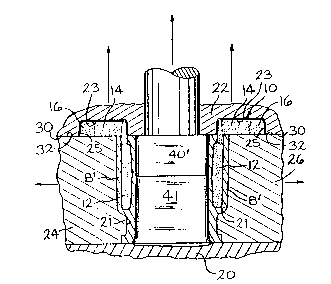
I;IG. 3 is a section in the direction of the
l~rrows 111-111 through Ih~ cl~vity portions of the closed dic casting
20 ~lies for fol~miIlg a casting huv~ng a cavity formed by the core
shown in l'i6s. 1 and 2;
I:IG. 4 is a section taken ulong lines IV-IY
vf the core shown in Fig~. I and 2 showing a different s~t of dies
25 having a casting centrul cavity witl~ wall~ of low taper an(l o~ a
more uni~orm th~ckness than shown in Fig. 3.
3 5 :
~3UBSTITUl~ SHEET

WO 93/19871 PCI/US93/02988
~ 5 ~ 2 110 27 ~
l)ETAILEI) DI~SCRIPTION OI~ TlIE VIEWS
l~eferring first to Flg. 1, there is shown in perspective
D view of ollc cmbodiment of un expendable framed core 10 for
forming an elongated cnvity in a casllng. The core per ~e
comprises a 11ollow portion 12 for forming a cavity in a casting,
the upper ed~es of whicll portion 12 are lntegr~lly connected and
bridged by printout connections 14 to a surroundin~ rectangular
printout frumc 16.
Rcfcrring now to l'igs. 2 through 4, the specific COl'e
10 is shown Ivcated in the pockets 23 and 25 and/or cav~ty 21
of the movablc die ~2 of closed die casting dies. Only the
custing or n~olding portions of euch of the~e dies are shown, tlle
rest of the die~ being broken awuy. The portions shown are tlle ~~:
parting 8urîaces 30 and 32 in tl~c movable and stationary die~ 20
und 22, whi(:l~ parting surfaccs contuin the pockets and c~vities
for the core ulld it~ prilltout portion shown in Figs. I und 2,
plus t~le castil)g formed thercin, numely the ca~ting B or B'.
'I`l~c die parts shown ill Figs. 2 through 4 comprise u : .
stutionary die 20 with 8 movul~le die 22 which carries the two
opposing slidcs 2~ and 26; the last three movable dies move in
the direction of the arrows shown in Fig~. 3 and 4. In Fig. 2,
ol~ly the movahle die 22 i~ ~hown snrrounding and seating the
plintout6 14 ulld 16 of tlle Cole 10.
ig9. 2, 3 und 4, tllCl'C are also 6hown the steel
mundrels or (:ores 40, 4D' und 41 fol forming the hollow inside
of the castin6s B and B'. Steel mandrels 40 and 40' are fustened
in the movul)l~: die 22. In Fig. 4, thc steel cores 40' and 41 are
~ttached to tl-c movable und stationury die6 22 and 20, respectively,
und only extclld halfwuy thro-lgh thc hollow in the cast~ng B' from
euch open end thereof, Thus a half or les~ d~gree of taper may : .
bc formed on llle insidc wall of tlle casting B' so thut this wall is ~:
8UBSrITUTE SHEE~

WO 93/19871 PCl/US93/02988
- 6 - 2 1 1 ~ 2 ~
relatively tl)ill und of ~u~stunliully uniform thlckne~s. This leduces
tlle amount of machinil-g tllot l~s to be done in the hollo~v portion.
Accordingly, this feature reduccs tl~e thickness of the c~sting walls,
improvc~ thc density of the casting, reduce~ porosity of the casting,
5 reduce~ the weight of thc ca~ting, and produces a casting witll more
uniform wall thickness. Furthermore, a framed printout enables
cores to be formed in core boxe~ without h~ving to have under-
cutting movable p~rts in the core box.
Although the embodiment of this invention is directed
to a core for a hollow ca~ting, it should be clearly und~rstood
that other forms of hollow ca~tings can be msde with expendable
cores with framed printouts, which ca~tings are open on at lea~t
one side, namely thst of the parting surfaces between tlle die~
15 a8 shown in Fig. 2, and h~ve other shaped expendable cores
with frsmed printouts. -~
While there are de~cribed above the principles of thi~
invention ir. connection with the specific spp~ratus, ~t i8 to be
20 clearly understood that thi~ description i8 made only by way of
example and not a~ a limitation to the scope of thia invention.
SUBSTITUTE SHEET

Representative Drawing
A single figure which represents the drawing illustrating the invention.
Administrative Status

2024-08-01:As part of the Next Generation Patents (NGP) transition, the Canadian Patents Database (CPD) now contains a more detailed Event History, which replicates the Event Log of our new back-office solution.

Please note that "Inactive:" events refers to events no longer in use in our new back-office solution.

For a clearer understanding of the status of the application/patent presented on this page, the site Disclaimer , as well as the definitions for Patent , Event History , Maintenance Fee  and Payment History  should be consulted.

Event History

Description Date
Application Not Reinstated by Deadline 2000-03-30
Time Limit for Reversal Expired 2000-03-30
Deemed Abandoned - Failure to Respond to Maintenance Fee Notice 1999-03-30
Inactive: Status info is complete as of Log entry date 1998-10-14
Inactive: Application prosecuted on TS as of Log entry date 1998-10-14
Inactive: RFE acknowledged - Prior art enquiry 1998-10-14
Request for Examination Requirements Determined Compliant 1998-09-28
All Requirements for Examination Determined Compliant 1998-09-28
Application Published (Open to Public Inspection) 1993-10-14

Abandonment History

Abandonment Date Reason Reinstatement Date
1999-03-30

Maintenance Fee

The last payment was received on 

Note : If the full payment has not been received on or before the date indicated, a further fee may be required which may be one of the following

  • the reinstatement fee;
  • the late payment fee; or
  • additional fee to reverse deemed expiry.

Please refer to the CIPO Patent Fees web page to see all current fee amounts.

Fee History

Fee Type Anniversary Year Due Date Paid Date
MF (application, 5th anniv.) - standard 05 1998-03-30 1998-02-23
Request for examination - standard 1998-09-28
MF (application, 2nd anniv.) - standard 02 1995-03-30
Owners on Record

Note: Records showing the ownership history in alphabetical order.

Current Owners on Record
DOEHLER-JARVIS LIMITED PARTNERSHIP
Past Owners on Record
ROBERT I. BADENHOPE
Past Owners that do not appear in the "Owners on Record" listing will appear in other documentation within the application.
Documents

To view selected files, please enter reCAPTCHA code :


To view images, click a link in the Document Description column. To download the documents, select one or more checkboxes in the first column and then click the "Download Selected in PDF format (Zip Archive)" or the "Download Selected as Single PDF" button.

List of published and non-published patent-specific documents on the CPD .

If you have any difficulty accessing content, you can call the Client Service Centre at 1-866-997-1936 or send them an e-mail at CIPO Client Service Centre.


Document
Description 
Date
(yyyy-mm-dd) 
Number of pages   Size of Image (KB) 
Claims 1998-11-06 2 65
Claims 1995-08-20 2 92
Abstract 1995-08-20 1 55
Cover Page 1995-08-20 1 22
Drawings 1995-08-20 4 117
Description 1995-08-20 6 206
Representative drawing 1998-12-15 1 16
Acknowledgement of Request for Examination 1998-10-14 1 172
Courtesy - Abandonment Letter (Maintenance Fee) 1999-04-27 1 187
Fees 1998-02-23 1 36
PCT 1993-11-29 18 453
Fees 1997-02-24 1 24
Fees 1996-02-20 1 27
Fees 1995-03-06 1 25