Note: Descriptions are shown in the official language in which they were submitted.
21 10394
-
Recyclinq Process for Riqid Polyurethane Foam
Specification
The invention relates to a process for the recycling of
rigid polyurethane foam and the production of molded pieces of
pretreated rigid foam by comminuting the starting product to c 10
mm, mixing it with a binder (polyurethane adhesive) and pressing
it at temperatures between 100 and 200C and a pressure of up to
20 N/mm2. The invention relates also to an installation for
processing the rigid polyurethane foam, comprising a mill, a
.
slzlng screen, a mlxlng devlce, and a press.
In a known process of this type (Japanese Application 57-
34926 and French Application 20 29 622), material for packaging
and insulation purposes is produced from the particles of a rigid
polyurethane foam and a binder These particles are comminuted
suitably to below 20 or 10 mm, mixed with the binder, and are
then compressed in a heated press, and the boards thus obtained
are used as a thermally insulating material. These boards are,
however, not elastic and break-resistant enough to use as boards
per se, but at most can be used as a substitute for rock wool or
similar mats. East German Patent 144 885 introduces a process
for producing molded pieces of polyurethane foam waste wherein
comminuted polyurethane foam waste with a particle size between
0.5 mm and 10 mm diameter are moistened with a rubber solution.
This starting material is used to produce boards, coatings, and
2 1 1 0394
other molded pieces. It is also known (from German Patent 24 39
672) that flexible floor covering boards are produced by
plastifying shredded synthetic leather waste and other comminuted
materials of thermoplastic synthetic material in an extruder and
to produce from the material processed in this manner, by way of
a press device, a web that is then cut into individual boards.
In another known process, non-slipping coating material is
produced from a mixture of integral foam granulate, flakes, and
soft polyurethane foam in a heated press at approximately 190 to
200C (East German Patent 114 927). The soft polyurethane foam
flakes hereby function as a binder.
Finally, German Patent 38 44 664 reveals that the material
is first compressed with low pressure in a two-step process from
suitably comminuted polyurethane foam and a binder, and that this
material is then finished by compression in a second step with a
higher pressure (4 N/mm2). The boards manufactured in this
manner supposedly are superior to particle boards in terms of
elasticity and breaking resistance. A disadvantage, however, is
that this process essentially presupposed clean production waste.
It was also found that comminution to 20 mm and below, i.e. to
approximately 10 mm, is insufficient for performing the process
without any problems. It is particularly disadvantageous that
the process requires discontinuous steps, since the press must be
stopped for some time after reaching the end of the compression
path before the pressure can be released and the material is
unmolded. The output of an installation working according to
21 1 0394
thls descrlbed process ls thus llmlted.
The lnventlon ls therefore based on the task of
creatlng a process and an lnstallatlon wlth whlch PU foam
recycllng materlal wlth contamlnatlons can be processed ln a
safe and largely contlnuous manner.
The lnventlon provldes a method of recycllng rlgld
polyurethane foam and produclng molded pleces of pretreated
rlgld foam, comprlslng the steps of commlnutlng a startlng
product to greater than zero but less than about 10 mm, drylng
the startlng product to approxlmately 2 to 4% resldual
molsture, mlxlng a blnder wlth the startlng product, fllllng
multl-part molds wlth the mlxed startlng product and blnder,
locklng and presslng the molds together by generatlng
compresslon pressure, compresslng the molds at greater than
amblent but less than or equal to approxlmately 20N/mm2 whlle
malntalnlng ventllatlon passages, heatlng the molds externally
untll the molds reach temperatures between approxlmately 80
and 180C., keeplng the molds closed for a predetermlned
holdlng tlme, and releaslng molded pleces from the molds.
The lnventlon also provldes a method of recycllng
rlgld polyurethane foam and produclng molded pleces of
pretreated rlgld foam, comprlslng the steps of commlnutlng a
startlng product to less than about 4 mm but greater than 0
mm, drylng the startlng product to approxlmately 2 to 4%
resldual molsture, fllllng startlng product ln multl-part
molds deflnlng molded pleces, compresslng the molds ln a
compresslon phase wlth approxlmately 2.5 to 5N/mm2 of
pressure, malntalnlng the pressure for a predetermlned holdlng
tlme, heatlng the multl-part molds durlng the set holdlng tlme
-- 3
27026-31
A
` 2110394
to a temperature not less than 800 and not greater than
180C., and removlng molded pleces from the molds.
The lnventlon further provldes a apparatus for
processlng rlgld polyurethane foam, comprlslng a commlnutlng
unlt for recelvlng and pulverlzlng a startlng product, an
lntermedlate bunker for recelvlng and holdlng a pulverlzed
startlng product, a drylng devlce comblned wlth the
lntermedlate bunker for drylng the pulverlzed startlng
product, a mlxlng devlce for recelvlng a drled startlng
product and for mlxlng the drled startlng product wlth a
blnder, and a molded part productlon devlce for moldlng a
mlxed startlng product lnto a molded plece.
The lnventlon stlll further provldes an apparatus
for processlng rlgld polyurethane foam, comprlslng a
commlnutlng unlt, a presortlng bunker for recelvlng a startlng
product from the commlnutlng unlt, a meterlng screw connected
to the bunker through whlch a sorted startlng product ls
removed, a meterlng pump for recelvlng the sorted startlng
product and for addlng a blnder to the sorted startlng
product, a mlxlng devlce for recelvlng the mlxed startlng
product from the meterlng pump, a drylng devlce comblned wlth
the mlxlng devlce, and a press for recelvlng the drled
startlng product and for formlng molded pleces.
The process of the lnventlon flrst provldes drylng
ln order to prevent tenslle forces due to the evaporatlon of
the water durlng the presslng process and to slmultaneously
ensure even heat conductlon wlthin the molded plece. Should
the molsture content of the startlng product be below 2 to 4~,
- 3a -
A 27026-3l
21 1 0394
a sultable molstenlng would be requlred, slnce only ln thls
case can a thorough heatlng of the pressed plece be ensured.
At the sa~e time, there ls a tendency for lsocyanate to react
wlth alr humldlty or molsture, whlch ensures the hardenlng
process. Then the sultably pretreated startlng product ls
fllled lnto a multl-part mold that ltself acts as a press,
slnce the molded parts can be pressed
- 3b -
A 27026-3l
21 1 0394
-
against each other and then can be locked, so that the pressure
generated by the pressing together of the two molded parts is
maintained. This entire process is first performed without
heating, but with the mold itself being warm. The molded
material reaches its final temperature only when the mold is
heated externally, so that a substantial continuity of the
process of the invention is made possible. The individual molds
filled with the molding material, for example, can be transported
through a furnace so that a certain continuity is achieved and
ensured. After a suitable holding time following the conclusion
of the heating, the molds can then be removed from the heating
zone, they can be opened, and the molded pieces can then be
unmolded. The molded pieces created in this manner are suitable
for a large variety of applications; it is possible, for example,
to produce cable drums or the individual molded parts needed for
the manufacture of cable drums, which can then be assembled into
cable drums. Such cable drums are subject to significant stress
and are able to absorb this stress without problems, since the
molded parts manufactured in this manner have high stability and
elasticity values. Boards should also be considered molded
pieces.
An advantageous binding capability is achieved if the
starting product is comminuted to ~ 2 to 4 mm while maint~;n;ng a
dust portion of approximately 30~, if it has 8 to 40 g/sec of
isocyanate in the form of a spray mist added, and if it is then
processed into molded pieces. It was found that with such a
21 1 0394
-
mixture, a favorable particle distribution is achieved that
ensures accordingly good stability values. In contrast, higher
dust content results in a loss of stability of the hot molded
piece that has not yet been unmolded and is significantly
brittle. Higher contents of larger particles have the inherent
risk that breaks can occur at the surface of the molded piece,
again resulting in potential problems. Since the starting
product first must be compressed without simultaneous heating, it
is advantageous if the compression pressure within the mold is
continuously brought to max. 20 N/mm2, whereby this high specific
pressure is exploited exclusively for reaching the press path and
for locking. It does, however, ensure that the pressure
necessary inside the mold for joining together the molded piece
is made certain. A favorably acting binder is added to the
mixture in the form of the isocyanate. Suitable for this are
li~uid, solvent-free diphenylmethane-4,4'-diisocyanates with
isomers and higher functional homologs. The amount depends on
the volume of the mixture. This isocyanate or isocyanate mixture
is stored at a temperature of 25 to 30C, at least at room
temperature, and is sprayed on in a suitable manner. The molds
are then also unlocked under pressure.
To ensure that the material is then heated to a sufficiently
high temperature, it has been provided that the molded material
is heated in the mold, e.g. when passing through a furnace, to
i 130C. The mold is heated by being passed through a tunnel
furnace that is divided into at least two zones in order to
21 1 039~
-
shorten the passage times. The mold is first heated as fast as
possible to the desired temperature, whereby a fast heat transfer
requires that the furnace temperature is clearly above the
desired value for the mold. The furnace temperature should be
above the desired value, especially if a third zone is provided
inside the tunnel furnace. Once the mold has the required
temperature, the holding time must also be considered. In this
context it can be assumed that, depending on the heat capacity of
the mold, a limited time at the end of the holding time also can
be spent outside the heated zone. The holding time is preferably
10 - 20 min.
The application of this process unexpectedly makes it
possible to solve a large disposal problem by mixing aggregates
such as PVC granulate or even cable trash or cellulose in the
form of paper or cardboard, with a content up to 80~, to the
starting product during comminution. In spite of the metal
components, the compressibility and stability of the end products
is not significantly affected in a negative manner.
Incorporation of the waste materials is possible, whereby
cellulose, preferably in the form of paper, is added to the rigid
foam, mixed with it, and is then processed further.
Surprisingly, this material (cellulose) is incorporated
completely into the mixture without requiring a change in the
procedure.
In cases where a suitable tunnel furnace or similar heating
device suitable for continuous heating of the molded pieces or
2 1 1 0394
molds is not available, it is advantageous if the starting
product is dried to a residual moisture content of 2 to 4~ or
more, if it is then compressed in a compression phase with 2.5 to
5 N/mm2, and if the pressure is then maintained for a predefined
holding time during which the two-part tool is heated to 80 to
180C, whereupon the molded pieces are unmolded. Although such a
process has the disadvantage that, due to the imperative holding
time in the actual press, only a discontinuous process can be
performed, it is nevertheless ensured that a good processing and
safe ventilation of the molded pieces is achieved. It is
advantageous in this case if the compression phase and holding
time are calculated according to the formula t(min) = s(mm)/2 or
more, whereby s is the greatest thickness of the molded piece.
It also must be taken into account that the compression time is a
factor in the dimensional stability and distortion of the molded
piece: if the time is too short, the tendency to distort becomes
greater. The given compression of 2.5 to 5 N/mm2 as a specific
pressure is usually sufficient, especially if the surface of the
molded piece can be loaded uniformly, something which is possible
in the process according to the invention by heating the tool
[and] correspondingly subjecting the tool to pressure. According
to the invention, typical compression ratios hereby are in the
range from 1:6 to 1:12 to which the starting product is
compressed. Depending on the material it may be practical to
choose the pressure so that the press path is reached gradually
but more clearly before the total time has passed. Then the
21 1 0394
-
compression is locked down mechanically or hydraulically by way
of the reached press path, i.e. until the end of the holding
time. To ensure a release of the molded piece from the form or
the tool, the invention provides that the tool is equipped with a
roughened surface and is sprayed with a suitable releasing agent
prior to being inserted into the mold.
To shorten the individual cycle times, it is provided that a
catalyst is added after the mixing, or simultaneously. It is
useful that the mixture is filled simultaneously and in a
predefinable and tuned cycle into several molds that are
integrated into turntables, that the molds are then subjected to
pressure, and after a waiting time of one to several minutes the
molded part can then be unmolded, and the mold can be cleaned.
The compression and heating process can be significantly
shortened by the corresponding mixing process, the previous
comminution to below 5 mm, and the addition of catalysts,
preferably suitable accelerators. Hereby the moisture in the
mixed products has a positive effect, so that it is also
conceivable to specifically increase the mentioned drying limit
of up to 4~. Hereby it is also possible to add material that was
not pretreated, i.e. more or less undried material, since the
catalyst then can act faster and more uniformly. In this
process, it is also advantageous that an improved quality is
achieved with the added catalyst, i.e. molded parts or boards
that are characterized by high elasticity, as well as breaking
resistance. It is also advantageous that the output can be
21 1 0394
-
significantly increased through the possibility of using several
turntables arranged parallel to each other. The mold is
subjected to a pressure of 3 - 10 N/mm2. A binder and catalyst
are added after being preheated. In the installation for
performing the process of the invention, the mixing device is
preceded by a drying device, or the mixing device is equipped
with a dryer. The press is furthermore constructed as a two- or
multi-part mold whose parts can be locked against each other, and
where the molds are constructed so as to be transportable through
and heatable in a tunnel furnace and equipped with ventilation
slots or bores. With such an installation it is possible to
operate almost continuously, although the individual steps
naturally must be performed separately. But especially since the
time-consuming drying is possible without any replacement of the
mold containers, if the tunnel furnace is constructed
correspondingly, the advantageous, uniform flow of the overall
process is ensured, especially since the degree of dryness can
also be changed. The process can even be realized with a
residual moisture of 10~. The ventilation prevents tearing and
blistering, etc., as well as damage that could influence the
stability of the final product.
According to a useful design of the installation, the molds
are arranged on a turntable that also extends through the tunnel
furnace and that exhibit spacers and self-braking rollers. This
makes it possible to guide the containers in the tunnel furnace
in very short intervals and to keep them, so that they are passed
21 1 03q4
-
uniformly through the tunnel furnace while they are kept spaced
on the r~m~;n;ng carousel according to the necessary partial
steps without necessarily requiring suitable holding devices.
This makes it possible to operate the entire installation with
little personnel, which is advantageous especially in view of
today's high operating costs.
This modified process is performed on an installation where
the mixing device is preceded or followed by an adjustable dryer,
or where the mixing device is equipped with an integrated dryer
and where the press consists of a bottom part with contour
elements and attachment, as well as an upper part that can be
inserted into the bottom part and that has contour elements,
whereby the respective contour elements are heatable and where
the upper part is equipped with ventilation openings. This first
enables a suitable preparation of the charged material by
suitable adjustment of the moisture content to 2 to 4~, whereupon
the material prepared accordingly is then fed to the press and is
here simultaneously heated and compressed by the correspondingly
heated contour elements. In this way the compression or
recycling process can be made more uniform and safe so that, as
already mentioned, starting products containing decontaminations
also can be used without problems. It is even possible that the
content of aluminum foil cuttings, for example, or comminuted
aluminum chips is increased, or that even such a content is
provided, which influences the capability of the pre-product for
heat conductance and thus shorter process times. These foreign
21 1 0394
-
parts, together with the moisture, result in an advantageous
uniformity of the overall compression process, as well as the
processing itself.
Further optimization is achieved with an installation that
provides, in addition to the known components, that the mixing
device is associated with several flanges with branching
conveyors, that the branching conveyors have admixture valves for
the catalyst, and that the branching conveyors are followed by
turntables with integrated molds, a filling station, a press
station, and a transfer station. This makes it possible to
produce, with a cutting mill and a m; Xl ng device, a large number
of molded parts almost continuously, whereby the mixing device
simultaneously charges several branching conveyors via
corresponding flanges and the mixed product is fed to the
turntables, and thus to the molds during the addition of the
catalyst. These turntables hold, among other things, the press
station where the molds, and thus the filled-in polyurethane
foam, binder, catalyst, and other substance mixtures, can be
effectively molded and can also be kept in this mold. Because of
the relatively short path on or in the turntables, the heating
power that must be applied is relatively low, especially since,
due to a preheater and a reheater, a heating of the press station
is not necessary. By separating the individual pressing and
heating processes, the corresponding aggregates can be realized
in a much more simplified form.
2 1 1 0394
-
If it is useful, due to the product used, that an extended
reheating station is provided, it is possible, according to the
invention, that the turntables be equipped with a bypass into
which a tunnel furnace with small ~;men.qions or in small
~;m~nqions has been integrated. The individual molds pass
through the bypass and the tunnel furnace, they are heated or
kept hot there correspondingly, and they are opened and emptied
at the end of the tunnel furnace. It is then possible to
perform, after a suitable cleaning of the molds, a corresponding
preheating still in the tunnel furnace by utilizing the waste
heat, so that the individual molds, upon reaching the filling
station, again have the desired temperature for holding the mixed
product and for the further transport following the closing of
the molds.
The uniformity in the output of molded parts or boards that
was already described before is ensured by designing all
turntables so as to transfer from the side of the transfer
station to a common conveyor belt, whereby the predefined cycle
sequence ensures a tight juxtaposition and transport of the
individual molded parts or boards.
The invention is particularly characterized in that it
proposes a process and an installation with which a great variety
of mixtures of rigid PU foam and similar materials can be
recycled, whereby the resulting material is used to form molded
parts and boards of various thicknesses (5 to 30 mm and more)
which can be used for a variety of applications. It is hereby
21 10394
-
advantageous that a specific adjustment of the moisture content,
catalyst, mixing-in conditions, e.g. of paper, and other factors,
such as temperature and pressure, work together to make available
a process that enables a safe process control, so that molded
parts that can be reproduced flawlessly can be produced. These
molded parts have a smooth surface, and a high stability and
elasticity, so that they can be used advantageously for a variety
of applications. It is optimal if an installation whose
characteristics ensure a safe performance of the process is
associated with the process. An almost continuous operation is
ensured.
Other details and advantages of the object of the invention
are found in the following description of the pertinent drawing
that shows preferred embodiments with the necessary details and
parts.
Fig. 1 shows an approximately continuously working
installation for the recycling of PU foam;
Fig. 2 shows a top view of a molded part of recycled
PU foam;
Fig. 3 shows a cross-section through the molded part
according to Fig. 2;
Fig. 4 shows a different design of the installation
for processing recycled PU foam;
Fig. 5 shows an installation with several parallel
turntables; and
~_ 2 1 1 0394
Fig. 6 shows an installation with catalyst and paper
charger.
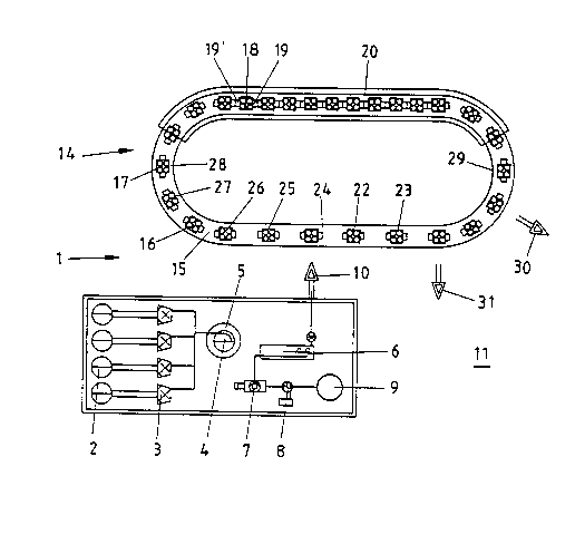
Fig. 1 shows a processing installation (1) that is first
equipped with several daily silos (2). Here the starting product
is stored and is fed as needed to a comminution unit, preferably
a cutting mill (3), and it is then stored in the intermediate
bunker (4). In the design shown in Fig. 1, this intermediate
bunker (4) can be combined with a drying device 5 so that the
material here can be brought specifically prior to the mixing
(injection) with the isocyanate to a moisture of 2 to 4~ (-10~).
From the intermediate bunker (4), the starting product that
has been brought accordingly to a uniform moisture is fed to the
mixing device (6). A corresponding mixing device with a screw
enables a uniform application of the isocyanate via the metering
pump (7) to which the isocyanate is fed from the daily container
(8) or the large tank (9). The isocyanate is applied to the
starting product moving inside the mixing device (7) via the
metering pump (7), e.g. with high pressure, preferably 60 bar.
(1) designates the pre-product filling device that is here
suggested only generally with an arrow, while the supply storage
(11) is provided for storing the produced molded parts.
An important second part of the processing installation (1)
is the molded part production device (14) in the form of a type
of carousel. The conveyor belt that operates approximately in a
circle or the carousel (15) is equipped with molds (16, 17, 18)
14
2 1 1 0394
that exhibit braked wheels, for example, so that they are carried
along evenly by the conveyor belt (15) as long as they are not
held fast by holding devices, e.g. in the tunnel furnace (20).
Hereby the use of spacers (19, 19') ensures that the molds always
have identical intervals between them.
(22) first designates the mold cleaning station that is
preceded by the tool cleaning station (23). The suitably cleaned
molding containers (16, 17, 18) are then passed under the filling
station (24) so that an even filling of the bottom part with
molding material or starting product is possible. At the next
station, i.e. the so-called correction or supplementation station
(25), an intermediate plate is inserted, for example, which is
advantageously roughened on both sides. In the next work cycle
the upper mold can then also be filled with molding material,
whereupon the cover plate is added on top at the next correction
and supplementation station (27). Also conceivable are multi-
story boxes.
The molds (16, 17, 18) are closed at the molding container
closing station (28) and are then locked.
Then the molds (16, 17, 18) filled with compressed molding
material reach the tunnel furnace (20). Here the individual
molds (16, 17, 18) stack against each other, whereby, as already
mentioned, an even interval is ensured via spacers (19). Holding
devices (not shown here) make it possible for the individual
molds (16, 17, 18) to pass through the tunnel furnace (20) in the
closest possible interval.
2 1 1 0394
Upon leaving the tunnel furnace, the molds (16, 17, 18) are
then again separated so that they can be unlocked in the cycle at
the molding container unlocking station (29) and can be divided
at the strip-down station (30), so that the individual molded
parts can be removed at the molded part removal station (31). As
already mentioned before, they are then transported to the supply
storage (11) and are stored there until they can be processed.
Such a molded part (32) is shown as an example in Figures 2
and 3, whereby it is clear that very complicated molded parts can
be produced in such a mold (16, 17, 18). They have not only
corresponding bores or recesses (33, 33'), but also corresponding
edges and curves.
Fig. 4 shows an installation in which molded parts (32) are
produced in a discontinuous process. As already mentioned above,
the starting product is first brought in the cutting mill (3) or
a similar comminution tool to a uniform grain size, whereby the
rod part shall be approximately 30~. In the presorting bunker
(34), a certain presorting then takes place, i.e. suitable
material is kept in partial bunkers (34', 34", 34"') and is then
removed via a metering screw (35) and is supplied to the further
process. (7) designates the metering pump through which the
isocyanate or other binder is added before the suitably wet
product to which the isocyanate has been added, i.e. the binder,
reaches the mixing device (6), in this case a long mixing screw.
This mixing screw is combined with a dryer (36) at its top end,
so that the material that is possibly still too moist is brought
16
21 10394
to a specific moisture content. It is useful, however, that this
dryer (36) precedes the metering screw (35).
(37) stand for the press in its entirety, in which a
discontinuous compression of the material is performed, whereupon
this material leaves the press (37) again as a molded part (32)
(not shown here).
Fig. 5 shows a processing installation (1) in which the
rigid polyurethane foam shall and can be recycled. From the
daily silo (2) (not shown here) a corresponding starting product
is fed to a cutting mill (3) in order to be cut or comminuted
there to the desired particle size of below 5 mm. The
intermediate bunker (4) in this case is a container that has a
drain funnel which is not shown here.
Via the intermediate bunker (4), the starting product
reaches a mixing device (6), where polyurethane adhesive is added
and injected specifically and in the necessary or desired amount
via a metering pump (7). Below the mixing device (6) runs a
distribution conveyor (12) through which several branching
conveyors (21, 40, 43) that are flanged to it via flanges (13,
39, 42) are supplied with the mixed product.
Connected to the branching conveyors (21, 40, 43) are
turntables (14, 41, 44) on which or in which the further
processing of the mixed product is performed before the end
products fall onto the conveyor belt (15) and are fed from here
to the storage place (46).
2 1 1 0394
-
The individual turntables (14, 41, 44) are equipped with
several molds (16, 17, 18) that are filled with mixed product and
are then passed around the turntable (14, 41, 44) and influenced
accordingly.
The molds ( 6) are first filled in the filling station ( 24)
with the starting product, whereupon the two- or multi-part mold
(16) is closed in order to be brought from here to the heating
station (27). The heating station (27) may simultaneously also
be the station where the molds are closed. In the area of the
press station (28), the compression then takes place in the mold
(here 18) to the desired thickness of 10 - 30 or more mm.
After leaving the press station (28), the molds (16, 17, 18)
reach the unlocking station (31). Here the molded part (32) is
transferred to the conveyor belt (15) and is then transported as
a cooled or solidified molded part (32 ' ) to the storage place
(46) .
To achieve a uniform mixture of rigid polyurethane foam and
other components and binder in the form of polyurethane adhesive,
it is important that the polyurethane adhesive is added uniformly
to the mixing device ( 6) via the metering pump ( 7) . The mixing
device (6) hereby has a nozzle bar or nozzle system (38) that
extends over a large part of the length of the mixing device ( 6),
so that an early and simultaneous mixing of the starting product
is possible.
Fig. 6 corresponds to the drawing of Fig. 1, where the daily
silo (2), the cutting mill (3), the intermediate bunker (4), the
18
21 1 0394
mixing device (6), and the metering pump (7) are concerned. Also
suggested here is the distribution conveyor (12) and the flange
(13) or (39) over which the branching conveyor (40) is operated
accordingly. As seen in Fig. 2, an admixture valve (47) is
provided in the area of the branching conveyor (40), and through
this admixture valve, the catalyst is drawn from the container
(48) and is injected into or sprayed onto the mixed product. By
designing and controlling the branching conveyor (40) suitably,
the mixed product is mixed accordingly with the catalyst. It is
useful that the container (48) is equipped with a metering pump
for this purpose (not shown here).
In contrast to the drawing in Fig. 5, the turntable (41)
here has a specially designed reheating station (45) assigned to
it. The individual molds (16) are transported in the manner of a
bypass (50) into a tunnel furnace (51), either on the turntable
or after having been pulled off the turntable, and they are here
subjected to the corresponding temperature of approximately
150C. The materials that have been compressed accordingly in
the press station (28) thus can be subjected to the necessary
thermal influence, whereby the influencing time of 10 - 20
minutes, or even longer, can be varied by way of the transport
speed of the individual molds (16, 17, 18).
In the area of the transfer station (31), the molds (16, 17,
18) are opened and the molded parts (32) are removed and
transferred to the conveyor belt (15) which is not shown here.
The opened molds (16, 17, 18) then have their temperature
19
~- 2 1 1 0394
maintained during their further path through the tunnel furnace
by exploiting the waste heat, or are again heated, cleaned and
returned to the filling station (24).
The processing installation (1) shown in Fig. 6 may also be
used advantageously for producing molded parts (32) of rigid
polyurethane foam and other components, especially paper, for
which purpose an addition funnel (52) is provided for suitably
prepared paper. This paper is added via the conveyor belt (53)
to the intermediate bunker (4), or to the conveyor belt leading
to the cutting mill (3). The latter has the advantage that a
certain mixing then already takes place in the cutting mill,
resulting in a uniform product which is then mixed further in the
mixing device (6) and then has polyurethane adhesive or another
binder added to it. It is then brought towards the turntable
(14, 41, 44) and compressed. The amount of the added paper or
added cellulose can be increased to up to 80~ by way of the
addition funnel (52) and the conveyor belt (53).
All mentioned characteristics, as well as those found only
in the drawings, are considered as essential to the invention,
both alone and in combination.
21 1 0394
Exam~le
The following represents an exemplary formulation for the
production of a flange with a diameter of 710 mm and a thickness
of max. 42 mm.
The material intended for processing stems from the
production of foam boards (edge clippings) and was delivered in
briqueted form. It was first comminuted in the cutting mill
(hole diameter 8 mm). Subsequent moisture determination showed
3.2~, so that no drying was required. The powder density of the
dried granulate was determined to be 0.12 g/cm3.
During screening analysis, the following particle size
distribution spectra were determined:
4 0.4
3.15 2.4
2 13.8
1 37.8
0.5 21.1~
~ 0.5 24.5~.
Non-PU components consisted of cuttings of paper and aluminum
foil, as well as rubber and leather particles that were permitted
for processing; particle size ~ 3.15 or ~ 4 mm. The available
plough share mixer had a volume of 0.34 m3. With a filling
volume of 80~, that meant that max. 32.64 kg of pre-product were
mixed. The charge was determined to be 30 kg, i.e. approximately
73~ of the filling volume of the mixer. Then 28.5 kg of PU
21
- 2 1 1 0394
granulate was added to thè mixer. The isocyanate injection time
for a specific injection amount of 32 g/sec was calculated to be
46.875 + 2 to 3 sec, i.e. 49 sec. The isocyanate that was used
was a Bayer PMDI from the daily container that was kept at 25C.
This isocyanate was added by the metering pump, which previously
had been brought to operating temperature, at 60 bar feed
pressure, to two single substance nozzles with a free diameter of
0.8 mm. The injection time of 49 sec was preselected on the pump
control. After the isocyanate is injected, the pre-product is
finished; but in the described case it remained in the mixture
until further processing.
The tool for molding consists of an electrically heated
bottom part with contour elements, an attachment for the bottom
part as a pouring funnel for the pre-product, and an electrically
heated top part with contour elements. The bottom part with
attachment is located on the press bed, the top part is attached
to the press ram. Attachment and top part are of a size so that
the top part fits into the attachment with little play and forms
in its deepest position a hollow space with the contour elements
of the bottom part, said hollow space being the counter-contour
of the flange.
The tool is in the open position, i.e. the press ram is
driven up together with the top part. Preparation of the tool
comprises the heating to the set temperature of 130C, the
control of mold cleanliness, and possibly cleaning of adhering
residues, the application of spray as a releasing agent, and/or
22
21 1 0394
-
the insertion of melamine resin-saturated releasing paper.
Process parameters in this case were presses with a constant
pressure, set in advance. The pressing force was determined in
the following manner:
The projected surface of the flange is 3,959.2
cm2; the medium desired density is approximately
0.8 g//cm3; a specific pressure of 3.5 N/mm2 is
necessary for this purpose. The pressing force is
calculated according to F = p x A = 4 N/mm2 x
3,959.2 cm2 = 1,584 kN, and was set by way of the
pressure control of the press hydraulics.
The mass of the molded part is calculated first by
conferring a high assumed mean density of the finished part of
0.9 g/cm3, in order to choose the amount for the pre-product
during the first use of the tool in such a way that difficulties
during the unmolding which arise from a compression that is too
low are avoided.
During the filling of the mold, the predefined amount of
starting product is weighed, placed into the attachment of the
bottom part, and distributed evenly. Now a sheet of releasing
paper is placed on the starting product, and the actual molding
process is ready to start.
The total time was determined for the highest thickness of
the molded part, i.e. 42 mm, and was estimated to be 42 mm : 2 =
21 minutes, whereby it must be considered that with a lower
21 1 0394
-
compression (approximately 1 : 4.8 at the observed point), the
pressing time should be chosen longer in order to ensure a safe
unmolding. Accordingly, a total time of 30 minutes was
determined for the first filling.
For the molding, the top part of the tool is driven down so
that the pre-product is surrounded on all sides by the tool and
is compressed, whereby the air contained in the loose bulk
escapes. The time of the beginning pressure build-up in the
hydraulic system is recorded for the consideration of the
pressing time. With the chosen parameters, this point is reached
when the top part is approximately 15 mm in front of the position
it needs to reach. This is the start of the calculation of the
pressing process that is associated with a gradual setting of the
top part. After 17 to 18 minutes, the top part has reached its
lowest position, and the press is hydraulically locked in its
posltlon.
If the total time for the molding has passed, the top part
is driven up together with the attachment of the bottom part, the
molded part is removed and is stored in a suitable manner, since
there is tendency for distortion, especially immediately
following the unmolding, until the hardening is completed. In
the case of the described flange, a plane storage place is
sufficient, and the temperature of the molded part must be
considered. The time until final stability is reached is
estimated to be approximately 24 hours for cooling in calm air;
it depends on the process parameters; longer pressing and slower
24
- ` 21 1 0394
-
cooling or hardening at increased temperatures in the furnace
result in a shorter time period.
In this example, an excess thickness of 9 mm was determined
during the first pressing. This can be remedied by increasing
the pressing force or, as in the example, by a proportional
reduction of the starting product amount, which was chosen very
high to start out with. The average thickness of the flange
according to the drawing is approximately 30 mm, i.e. it was 39
mm after the first pressing; the starting product amount
therefore must be reduced to 7,582 g. During the second
pressing, 7,600 g of starting product were used, and dimensional
stability was achieved.
This example relates to the discontinuous process. An
example for the process with the tunnel furnace would result in
much shorter cycle times and a higher continuity.