Note: Descriptions are shown in the official language in which they were submitted.
2 ~ 3 3
TECHNICAL FIELD
The outer diameters of conventional threaded pipe couplings
are substantially greater than the outer diameter of the pipe joints
that they connect and the same is true for most strings of casing and
tubing installed within oilwells, however, several constraints are
presented by oilwells that are not normally present in surface piping
systems. Each consecutive string including couplings, must pass
within a hole bore diameter established by a drill or by a previously
set string of pipe. Additionally, there must be sufficient clearance
between that bore and the maximum diameter of the string being run so
as to lower freely without sticking and to allow sufficient flow area
through the annulus then formed for fluids, without causing an
unacceptable pressure drop caused by friction of the flowing fluid.
Thirdly, oilwell strings must withstand axial tension and compression
loads caused by the weight of miles of pipe that may be hanging within
the well. Further, oilwell strings may be subject to external fluid
pressures being greater than internal pressures to thereby introduce
tendency to collapse. For these and other reasons, joints with upset
ends and high cost "premium connections" have been introduced to work
in the presence of such constraints. However, such solutions result
with the outer diameters of connections being greater than the outside
diameter of the pipe joints that they connect. There do exist,
connections for pipe not having upset ends wherein one end of a joint
is threaded externally and the other end is threaded with a mating
internal thread such that joints can be screwed together to result in
a connection with an outer diameter no larger than the pipe
mid-section. However, such joints, such as Hycril FJ Premium tubing
connections enjoy only 43~ axial tension strength as compared to the
unthreaded pipe wall, about the same as non-upset API tubing
connections. Presently, due to diameter constraints, a typical
oilwell pipe program may be: 5-1/2 OD x 2-7/8 OD x 1.6 OD. To be far
more advantageous, a 2-7/8 OD x 1.6 OD x 1.05 OD can often make an
installation possible due to clearance or cost reasons that the
sg/sp
2 ~
(lA)
typical program above could not, and in every case, a less expensive
and a more efficient installation should
sg/sp
-
33
(2)
result. Many tons of steel per oilwell may therefore be saved
from waste. When a pipe having no reduced wall thickness contains
fluid pressure, the axial stress within that wall caused by fluid
pressure is approximately one-half of the circumferential stress
05 within that wall caused by the same pressure and therefore a like
amount oE mechanical axial stress may be applied by pipe weight
or the like, without the axial stress exceeding the
circumferential stress. Reduction of the pipe wall thic~ness as
by a thread formed on a joint of non-upset pipe, will therefore
reduce still further, the magnitude of axial s~ress that may be
dedicated to s~pport the pipe weight. There is therefore a
substantial need for a non-upset, integral tubular connection
having a higher efficiency with no loss of the connections
ability to seal against fluid pressure.
For assembly of conventional threaded connections, the
external thread must be carefully aligned both axially and
angularly, with the internal thread before stabbing so as to
prevent cross-threading of the connection. It is then moved
axially to contact the end thread of the pin with a thread of the
box to thereby effect stab position. The length of the pin thread
that then projects into the box if any, is known as stab depth.
Then, while being careful to maintain said alignment, the pin is
rotated into the box by hand to a ~hand-tight~ position after
which, a wrench is used to tighten the pin to a position of full
makeup. The Accuracy of stabbing often determines the effect of
the connection. Connections that have been cross-threaded usually
leak even after a proper makeup. Connections that are put into
service in a cros-threaded condition will not only leak but will
rupture at a small fraction of the rated load. It is therefore
clear that a connection designed to prevent cros-threading is
highly desirable to eliminate ~he danger and damage that can be
caused by such leakage and rupture.
An upset pipe end is generally understood by the industry as
being a pipe end that has been heated to a temperature above the
lower critical temperature for the pipe metal and then formed
under great pressure so as to gather axially, metal of the pipe
wall and thereby increase substantially, the cross-section area
of the pipe wall at that end of the pipe. After upsetting the end
of a high strength pipe, API Specifications require that the
entire joint of pipe be quenched and tempered, all of which can
greatly increase the cost of a joint of pipç.
In an effort to improve the radial clearance and cost of a
tubular connection and still retain significant strength,
"near-flush" connections were introduced which comprise ~swaged"
pipe ends. Swaged pipe ends are formed at temperatUres below the
lower critical temperature, by moderate radial pressUres that
- -
i33
(3)
increase or decrease the mean pipe diameter of the swaged zone,
but do not substantially change the cross section area thereof.
The swaged end of a high strength pipe need only be stress
relieved at a temperature below the lower critic~l temperature,
05 which is far less costly than a quench and temPer. A pipe end may
be ~'swaged-in" to a smaller diameter to receive an external
thread or it may be "swaged-out" to a larger diameter to receive
an internal thread. Generally, the outermost diameter of
swaged-out ends is less than an API Coupling ~.~. but more than
pipe body O.D.
A typical family of swaged pipe connections having
e~ficiencies of 6~% may seem to be adequate to an engineer while
designing a well, if calculations indicate ~hat pipe weight and
fluid pressure will generate loads on the connections of only 50%
15 of pipe strength. However, many factors deep in the earth can
cause unexpected rupture of a connection, endangering both people
and the environment, when well designs are based on pipe stress.
For example: ~.19% strain will yield the body of API J55 pipe;
0.28% will yield N80; 0.38% will yield PllO. If a high efficiencY
connection allows the strain of the pipe body to continue, it
will usually accept 5% or more strain before rup'cUre. Howe~er, if
the parting load of a casing connection is less ~han the lpad to
yield the pipe body, then the connection will pa~'~ before strain
reaches the low limits given above. Strains o~er 1% are often
i~posed on the casing of wells that prod~ce from or near,
over-pressured and under compacted reservoirs, of which there are
many. If a connection parting load exceeds slightly, the load
that will yield the pipe body, then the casing string will accept
strains several times greater than if connection parting load is
slightly below the pipe body yield load. To safely mee'c strain
criteria for well design, connection efficiency sho~ld exceed the
value= 100 x (pipe yield strength/pipe ~ltimate strength).
Accordingly, casing cQnnection strengths should ex~eed by some
reasonable margin, the following % efficiencies: 73% for J55; 80%
for N80 and PllO API Pipe Grades.
2 ~ ~ t 133
(4)
Although most non-upset threaded pipe connections have
compressive axial strengths in the range of 50% as compared to
the pipe body strength, there are needs for plain-end threaded
pipe connections having much higher strengths. One such need is
05 for joints of "Drive-Pipe" in pipe sizes of 60" and larger, that
are hammered into the earth successively after connection with a
previous joint driven, to form long strings of pipe driven into
the earth. The API 8Rd Connection cannot be used for drive-pipe
because easy stabbing, low makeup torque and structural rigidity
10 is imperative for such joints. Drive-pipe strings are used as
"piling" to support the weight of other structures and are also
used as the first string in a deep well. To efficiently and
reliably transmit extremely heavy blows from massive hammers,
the threaded connection must not allow relative motion between
15 the box and pin members of the connection so as to prevent
loosening, leaking~wear and/or compressive failure. The API
Buttress connection is not used for such service because it
allows end-play between box and pin which dissipates the hammers
impact and allows leakage of the connection. Such connections
20 must also have high strength in tension so as to withstand high
bending loads and it must seal against fluid pressure after being
driven. Flush-joint drive-pipe connections offer less ground
resistance than collar-type or weld-on connections while being
driven and they cost much less however, the best flush-joints
25 available for Drive-Pipe have only 60% efficiency and are very
difficult to stab. When higher strength drive-pipe connections
are needed, the user must now use a weld-on type. Both types seal
on rubber whlch reduces the connections service life.
Therefore, a threaded pipe connection for large pipe sizes
30 is needed that:is cost effective; has high axial strength; stabs
easily; makes up with low torque; provides a reliable permanent
seal against dangerous fluids; resists handling damage; does not
leak or loosen after being driven into the earth.
BACKGROUND ART
A flush joint tubular connection has inner and outer diameters
substantially the same as the tubing joints which the connection
connects. A flush joint tubular connection made be the Hydril
40 Company and covered by numerous patents comprise a first straight
thread, a second straight thread of sufficient diameter to pass
within the bore of the first thread and a tapered mating seat
between the two joints of tubing which is a premium joint of
high cost and according to published data, enjoys only 42% axial
45 strength, relative to the pipe wall.
-
. ~
(5) f~ L ,~
Standard A.P.~. non-upset tubing connections comprise
couplings having outer diameters considerably larger than the
pipe outer diameter but still only enjoy approximately 42%
efficiency as above. A.P.I. does list a ~turned down~ collar
05 outer diameter to increase clearance between strings, however,
the "turned down~ diameter still exceeds substantially, the pipe
outer diameter.
No prior art discloses a flush joint tubular connection having
tapered threads, that when properly assembled, effects optimum
lO stresses within the small end of the external thread and ~ithin
the large end of the internal thread so as to provide a
connectio-n of maximum efficiency. Conventional pipe connections
have threads with like tapers and result in a constant
diametrical interference along the taper between the external and
15 internal threads, thereby causing excessive stresses or requiring
increased wall thickness at the end of the pipe. ~xcessive
stresses reduce the joint strength and an increased wall
thickness rules out a flush joint connection.
It is therefore clear that a flush joint connection having a
20 high efficiency as provided by the instant invention is needed
for use within oilwells and other pipe assemblies wherein radial
clearance is limited.
Standard pipe threads as well as A.P.I. threaded connections
have such a tendency to cross-thread that ~stabbing guides~ are
25 often used at a considerable cost of time and expense. Such
threads have an ex~remely shallow stab depth and a relatively
large thread depth, both of which add to the cross-thread
problem. Perfect alignment is difficult to attain under hormal
field conditions and often impossible to attain under difficult
30 conditions. Premium connections such as disclosed by Stone in
U.S. Patent 1,932,427 require even closer alignment to stab
because of the close fit of straight threads and the ~pin-nose"
seal 32, which is highly susceptible to damage. To applicants
belief no prior art comprised the combination of a deep stab,
35 thread height and thread diameter as required to provide a
tapered threaded connection that will stab easily and quiclcly
without the possibility of cross-threading. By way of an example,
a 2-3/8 EU 8rd A.P.I. tubing thread has a 2.473" pin end diameter
and a 2.437" box bore at the first thread which allows no entry
40 of the pin into the box at stab position. The counterbore of the
box allows entry of the pin only .446" affording at best, axial
alignment but no angular alignment so less than six degrees of
angular misalignment will allow it to cross-thread.
About 1940, A.P.I. changed from lOV threads to 8rd and a
45 substantial improvement resulted because less gauling occurred
during makeup of the threads. It was then commonly assumed "that
- -
.. . --
3 3
(6)
any thread finer than 8 threads per inch would gall and
cross-thread" and that myth persists today. However, the
improvement resulted almost entirely from the better thread form,
eliminating the sharp edge V threads. The present invention with
05 threads as fine as 20 per inch, run fast and smooth without
cross-threading, and it has other features as well.
Conventional ~near-flush" connections mentioned above, have
two-step straight box threads formed within swaged-out ends and
pin threads formed on swaged-in ends. Such swaged ends comprise a
10 single tapered zone extending axially from the pipe body of
original pipe diameters having a mean conical angle of taper of
approximately two degrees. Typically, such swaged connections are
rated by their suppliers as having from 50% to 75~~ efficiency
depending on wall thickness, and with a variety of fluid pressure
15 ratings. Such a swaged connection when compared to a 42%
conventional flush joint connection, has improved strength, but
at the expense of clearance.
To applicants best knowledge and belief, all such swaged
connections now on the market are swaged to form only the degree
20 of taper that approximates the lay of threads to be formed
thereto. Typically, before a thread is machined in the tapered
zone, a clean-up cut is made to assure there bein~ enough metal
to fully form the threads. Unfortunately, such a cut reduces the
cross-section area of the tapered zone which limits connection
25 efficiency- Additionally, production machining allows for only
approximate axial positioning of the pipe in the machine prior to
gripping the pipe in the chuck and such approximation can cause
further thinning of the tapered zone. Thirdly, if first
measurement of a freshly cut thread indicates that a thread recut
30 is required, then the swage must be cut off and the end reswaged
before even a 75% thread could be cut at that end. Therefore, in
addition to the basic disadvantages of a two-step thread having a
pin-nose seal, it is now even more clear why s~ppliers of pipe
threads that are formed on swaged ends cannot provide a family of
35 pipe connections with efficiencies greater than 75%.
Applicants Patent 4,813,717 which is in the line of priority
for the present application, discloses a connection with
selective efficiency between 75% and 100% for non-upset pipe
using a coupling in one embodiment per claims 1-17 and an
40 integral connection in another embodiment per claims 18-19. The
present invention is complimentary to said patent and teaches
configurations for connections having swaged ends. To applicants
best knowledge and belief, no non-upset integral connection is
currently available that will meet the strain design criteria
45 above. For users who prefer integral non-upset pipe connections,
there is clearly a need for one with an efficiency sufficient to
meet the strain design criteria defined above.
3 3
(7)
For purposes of this application, I define as follows:
"Pin" is an externally threaded portion of a tubular member;
"Box" is an internally threaded portion of a connecting member;
"Flank angle" is the angle measured between a thread flank
profile and the tubular axis;
05 "Included angle" is the angle measured between the flanks, in
the space between the flank surfaces;
"Dope" is a pipe thread compound such as specified in API 5A2
that has been developed for 8Rd threads over many years to have
an optimum combination of selected greases mixed with solid
particles of specific dimension and nature so as to provide most
desirable characteristics for sealing, lubricating and brushing
over a substantial range of service temperatures and pressures-
"Gap" is a distance that may exist between mating thread surfaces
when they are positioned in best mating contact with each other,
the distance being measured perpendicular to the surfaces.
The pipe thread form most widely used is the old "sharp-V"
having 60 degree included angle as specified in ANSI B2.1 for
AMERICAN NATIONAL STANDARD TAPER PIPE THREADS and in API 5B
Table 2.8 for API LINE-PIPE THREADS. Although ANSI B2.1 shows
thread sizes up to 24" and API SB shows thread sizes up to 20",
sizes above 4~" are seldom used because:their high makeup torque
makes field assembly impractical; such threads are very prone to
handling damage; they frequently leak, loosen or break and are
difficult to stab. Sharp-V threads are restricted to very low
25 pressure services by government and industry codes such as API
& ASME, who require the use of other connections such as flanged
or welded, when dangerous fluids are to be contained. In addition
to problems cited above, sharp-V threads often tear and gall
during makeup which can cause excessive torque and worse, such as
30 dangerous and costly leakage of fluid from within the pipe at some
unpredictable time in the future. In an effort to solve such
problems and because there is no reasonable alternative to the
use of threaded pipe connections for downhole use in oil and
gas wells, API adopted about 1940, the "8-Round" form shown in
35 API 5B Table 2.9 which has 8 threads per inch and an included
angle of 60 degrees, the flanks being connected by rounded roots
and crests formed with a radii 0.017" and 0.020~1 respectively.
Although thread tearing and galling were greatly reduced, the
retained 60 degree included angle still allowed axial and bending
loads to cause loosening, leakage and then pullout of a connection.
For many 8Rd connections, pullout determines the parting load and
leaks occur at much lesser loads.
i 3 3
(8)
The 8 Rd thread form, without regard to pipe strength, is limited
to only 5,000 psi service by API 5A due to such weaknesses. Both
sharp-V and 8 Rd form standards specify intentional mismatches
between crests and roots of mating threads like all other
05 conventional threads known to applicant, which in turn, acts to
increase the root gaps, which within tolerances, ranges from
0.005" to 0.011" for sharp-V and from 0.003" to 0.008" for 8Rd
even after the mating flanks are wedged together at full makeup,
which allows dope to leak through the root gap. As makeup begins,
10 the root gap substantially equals the flank gaps, as dictated by
the 60 degree included angle whereupon, solid particles in the
dope extrude helically from between mating flanks and out of the
connection as easily as it flows from the root gap. Thus, flanks
wedge against each other with virtually no solid lubrication
15 retained between them, which greatly increases galling tendency.
The coefficient of friction with just grease is 0.084, vs 0.021
with the solid lubricants, which can increase torque by a factor
of four. It is now clear how the root-gap/flank-gap ratio can
affect torque.
To reduce thread pullout, API adopted many years ago, the
"BUTTRESS THREAD FORM" depicted in API 5B Figs 2.5 & 2.6 for use
on casing strings. The 87 degree tension flank angle greatly
reduced tendency of pullout and an 80 degree compression flank
angle reduced to a lesser extent, tendency for axial loads to
25 jump the pin into or out of the box. However, such improvements
were traded for a loss of sealing ability, a loss of rigidity
and a cost increase as compared to API 8Rd threads. The Buttress
form has many more dimensions to control than the 8Rd form which
in turn, increases tolerance stack-up and results in flank gaps
30 of 0.002" to 0.008". Even if a low pressure seal is formed on
makeup, external loads imposed on such a connection cause end
play between the mating flanks which extrudes Dope to cause
loosening and leakage of the connection, particularly after the
dope has had time to dry. Such end-play was felt necessary by the
industry experts on API Committee 5B to prevent extreme torque
and galling if "wedging" between the 13 degree included angle
was allowed however, not obvious to them were the ill effects on
connection rigidity and sealability that they incurred by the
change. As a result, when critical jobs require both high strength
and good sealability, the operator must use more expensive "pin
nose" type connections that do not seal on the threads.
My force-vector analysis for flank-wedging mating threads
having no root-crest contact, shows unit frictional resisting
force: F = f(P)(l/sin T + l/sin C)/(l/tan T + l/tan C) where:
f=coefficient of friction; P= interface pressure; T=tension flank
angle; C=compression flank angle. When T=C then this equation
reduces-to F=f P/cos C, the conventional formula found on pages
3-28 and 3-29 of Marks Standard Handbook For Mechanical Engineers
- -
~ ~ ~ ~ i 3 3
(9)
8th ed which is correct when dope is allowed to extrude easily
from between the load bearing surfaces. Mark shows "sin" instead
of "cos" because that angle is referenced 90 degrees from mine.
Since both Sharp-V and 8Rd threads have flank angles of 60 degrees,
05 their torque is proportional to F= 2 f P when calculated in accord
with conventional practice.
API Committee 5B evidently thought that if they allowed flanks
of the Buttress form to wedge like the 8Rd form, that torque would
be proportional to F= 8.2 f P, which is 4.4 times torque for the
10 sharp-V or 8Rd form, and out of range for practical use. However,
since API Buttress threads do not wedge, then F= f P =.084 P. API
Bulletin 5C3 entitled FORMULAS AND CALCULATIONS FOR CASING, TUBING,
DRILLPIPE AND LINEPIPE PROPERTIES~ gives many formulas, but they
do not give a formula for torque because their test results were
15 so erratic. The reason why API 8Rd connections have erratic torque
is because a first connection may have large root gaps that will
prematurely extrude dope, resulting in high torque and leakage
while the next one may have small root gaps and much lower torque.
However, a well may have hundreds of threaded connections and only
20 one leaking connection can result in disaster.
Pattersons connection may have a more consistant torque than 8Rd
but because he does not wedge flanks, end-play will cause it to
loosen and leak when it is subjected to repeated service loads.
For many years, thread experts all over the world have used API
25 8Rd, Buttress and Pattersons threads, but none have recognized
features and advantages of the present invention.
The API Buttress thread form allows Dope to extrude through
gaps between the flanks which allow 0.002" to 0.008" end play
at full makeup. Even if the gaps are reduced to between 0.002
30 and 0.004" per U.S. Patent 4,508,375 to Patterson, end play will
still occur when external loadings are imposed to cause loosening,
extrusion and leakage at some unknown time later. Patterson also
evidently knew that wedging of his threads would cause extreme
torque, as evidenced by his 0.002" minimum gap allowed between
35 flanks that prevents wedging. Had the API committee or Patterson
recognized advantages of the present invention, they could have
solved their loosening, leakage and torque problems.
API Specification 5CT on Tubular Specifications states in
paragraph 5.19(a), "Pipe test pressures shall be held for not
40 less than five seconds" which tests the pipe wall strength but
does not test thread sealability because, it may take more than
(10)
an hour for pipe dope to extrude through the thread gaps to prove
a leak whereas, the required service life is generally between
five and fifty years. Therefore, many casing connections are now
on the market claiming high strength, good sealability and/or
05 reasonable torque, but they use a separate pin-nose seal in
addition to threads for holding the pin-nose seal together, which
increases susceptibility to damage and increases cost, which in
turn, prohibits their use for most applications. The resulting
failures of pipe connections in deep wells increases rework costs,
10 energy loss, danger to the public and damage to the environment.
The manufacture and use of large diameter pipe connections
present several problems not encountered with small connections.
Handling damage is much more probable and much more costly.
Reimert U.S. Patent 4,429,904 discloses a large diameter welded
15 on connection having special form Buttress threads that neither
wedge nor seal. The O-ring 76 and stop shoulder 73 are mounted
with a welded-on tubular member of increased diameter and radial
thickness, at a great increase in cost. A reliable connection
formed within dimensions of the pipe wall would save time,
20 energy, cost and the uncertainty of weld quality. Reimert also
reduces torque by preventing wedging of the thread flanks as
shown in Fig 9, but at a very high price. He also provides a
seal separate from the threads by means of an O-ring and a
pin-nose, but a seal that will degrade with time and that is
25 not retrievable with the pin to the surface of the ocean.
Many patents such as U.S. 2,094,492 to Janata and U.S.
2,196,966 to Hammer disclose high angle tension flanks to wedge
in cooperation with low angle compression flanks so as to keep
torque within useable range. However, low compression flank
30 angles sacrifice compressive strength of the connection which
tends to cause loosening and leakage if subjected to compressive
or bending loads. Others such as Patterson have high flank angles
for both tension and compression flanks but do not allow wedging
of the flanks that is necessary to prevent loosening and leakage.
Therefore, industry is clearly in need of a threaded pipe
connection having low torque, that stabs easily, that will seal
reliably and does not loosen when service loads are imposed on it.
i133 --
.
( 1 1 )
DISCLOSURE OF THE INVENTION
The present invention provides a tubular connection for
joints of plain end pipe or the like, having a first tubular
member formed with tapered external threads and a second
05 tubular member formed with tapered internal threads for
sealing cooperation with the external threads.
So as to avoid the pullout tendency inherent in a non-upset
threaded pipe connection formed with conventional 60 degree
thread flank angles with respect to the tubular axis, a thread
form is provided that has a load bearing flank angle of at
least 75 degrees with respect to the tubular axis, the
optimum angle depending on such factors as the pipe diameter,
the wall thickness and the material strength.
As taught by my series of patents beginning with U.S. Pat
2 ,766,829 which have enjoyed worldwide commercial success
for over 30 years in the oilfield, the space industry and the
nuclear industry, the taper of the external thread may be
formed at a lesser angle than the taper of the internal
thread so as to ensure a maximum primary sealing tendency at
the smallest pressure area so as to mimize the axial load
imposed on the connection due to internal fluid pressure. The
present invention may utilize this feature in combination
with other features. With this feature, initial thread
engagement occurs on the external thread at the small diameter
end only, simultaneously as a radially spaced relationship
exists between the internal and external threads elsewhere. As
the connection is tightened toward full makeup, thread contact
increases progressively from the small diameter end toward the
large diameter end of the threads. The threads may be
dimensioned such that at full makeup, the threads at the
large diameter end are in contact also.
The use of flank angles that reduce pullout tendency also
allows the use of a lesser thread depth than would be
practical with the use of conventional 60 degree flanks. In
turn, the lesser thread depth allows for a higher connection
efficiency because a smaller portion of the pipe wall is
removed to form the thread and thereby, a higher connection
efficiency is possible for a flush or near-flush connection.
Machines to swage pipe sizes over lO" are very expensive
and fewer large connections are threaded per run, so the cost
usually prevents serious consideration of swaging large pipe
connections. Yet the need for swaged connections several feet
in diameter exists for such uses as on drive pipe, for pipe
lines etc. Also a less expensive swaged pipe connection than
is now available is needed in smaller sizes for some uses.
1 3 c~ ~
(12)
For these and other reasons, the present invention discloses
a self-swaging connection having tapered mating threads of
desired dimensions that can be formed on plain end pipe where
upon make-up, the internally threaded box expands and the
05 externally threaded pin contracts within predetermined limits,
so as to provide a swaged connection of high efficiency. Before
assembly of the connection, the threads are dimensioned such
that: the box wall is thinner than the pin wall by a
predetermined amount at the large end of thread engagement;
the box wall is thicker than the pin wall by by a predetermined
amount at the small diameter end of thread engagement; the box
and pin walls are substantially equal in strength in a plane
intermediate the large diameter end and the small diameter end.
Thread dimensions are selected such that upon full make-up
of the connection: toward the large thread diameter end, the
box wall will expand to predetermined dimensions; toward the
small thread diameter end, the pin wall will contract to
predetermined dimensions; the box wall will expand about the
same amount that the pin wall contracts at the plane of equal
strength; to thereby effect sealing engagement of the threads
along their full length of engagement.
By way of example, the outer box diameter may be swaged
larger than the original pipe outer diameter by an amount equal
to twice the radial thread depth so as to effect a connection
efficiency of approximately 90%, or by an amount equal to four
times the radial thread depth to effect 100% efficiency- Within
reasonable design parimeters, the ratio of plastic to elastic
deformation effected will decrease with: thread depth decrease;
pipe diameter increase; pipe material yield strength increase.
In a connection of 100% efficiency, the pin face bore will
contract about the same amount that the box face O.D. expands.
After assembly, the threads will lie along a generally
steeper taper than the taper they were machined on. The threads
must be dimensioned before their assembly such that when the
box and pin are assembled to the hand-tight position, there
is a predetermined number of turns from the position of full
make-up so the angle of taper can effect the desired amount of
swaging of the box and pin as they are tightened to a position
of full make-up. The threads may be machined with a single taper
or on various taper combinations without departing from the
spirit of the present invention.
~ -" Jl ~ 4 ~
3 3
(13)
Such desired dimensions may effect: face widths of the box
and pin sufficient to prevent premature jumpout of the threads
when under axial loads; sufficient length of thread engagement
to ensure a fluid seal; a cross section wall area at the last
05 engaged thread of the box and of the pin to allow a selective
connection efficiency between 50 and 100%. For services that
can accept an efficiency less than 100%, the resulting bore
through the connection can be increased by tightening the
connection a lesser number of turns past the hand-tight
10 position than is necessary for a 100% connection.
Such swaging will usually be mostly plastic and partially
elastic. However, for large diameter pipes with thin walls and
high yield strengths, the swage could be fully elastic. Per
inch of diameter, all connections may have an elastic return
15 equal to: the yield strength of the material divided by its
t modulas of elasticity. The remainder of the swage if any, will
be in the plastic range and the pipe will not return.
Some services require pipe connections having higher bending
and/or compression strengths than normal service, such as for
20 use with drive pipe and marine risers used on offshore wells.
To provide such strengths, the thread form stab flan ~A ~ the
present invention may be increased as required and also, the
taper angle of the thread cone may be reduced to increase the
length of engaged threads within existing diameter constraints.
25 When the connection is provided with a pin shoulder that
abuts the face of the box upon full makeup, that shoulder adds
to the compression and bending strength of the connection.
;~ .4 ~
h, i
~ 1 4 )
The present invention provides a high efficiency threaded
connection for tubular members for easy assembly with the use of
pipe dope at relatively low torque, that seals reliably between
the mating threads and provides firm strength against repeated
05 mechanical shock loadings without loosening, leaking or failure.
A preferred embodiment is described below:
The connection has a pin and a box with mating threads for
assembly with pipe dope and is formed with 83 degree compression
flank angles and 83 degree tension flank angles, the tension and
10 compression flanks being connected by crest and root formed with
like radii positioned tangent with the flanks they connect, a
radial thread depth equal to two-thirds of the axial thread pitch,
box and pin thread forms being formed sufficiently complementary
to each other such that no gaps wider than 0.006" may exist upon
15 full makeup of the connection, but in no case is a gap allowed
~ n~l~r~
having an inscribed circle~greater than the quantity:0.33 L/psi,
where L= inches of helical thread length; psi=service pressure.
I have discovered that API Dope will readily extrude through
gaps greater than 0.006" because the solid particles are too
20 small to be clamped by the thread surfaces, so they flow along
the helix entrained in the grease. Such flow is in accord with
the laws of Rheology and is therefore slow and will often give
a short time indication of a seal. However, water pressure may
days later, push out the dope and cause a leak. Gas pressure may
25 channel through the dope in a matter of minutes. I have also found
that threads having lesser gaps will clamp the particles and
then extrude grease from between the particles while compressing
those particles to a thickness range between 0.006 and 0.0007"
depending on the specific interface pressure of a connection.
30 Therefore it is now clear, that to reliably and permanently seal
between mating threads with API dope, there must not be a gap
greater than 0.006" and that simultaneously, the mating thread
surfaces must not be required to compact solid particles to less
than 0.0007" thickness in order to reduce larger gaps to .006".
API 8Rd and Buttress threads have erratic torque because
they allow gaps greater and allow gaps less than 0.006". One
such connection may extrude dope prematurely and the next may
retain dope late enough during makeup such that torque is much
less.
All during makeup of a connection of the preferred embodiment,
the root gap will be approximately four times as great as the
combined flank gaps and therefore, as makeup begins, the dope
will slowly flow from between the flanks into the much larger
root gaps leaving solid particles between the flanks as compared
45 to fast helical flow along root gaps that tends to carry solid
particles out of the connection. Shortly before reaching the
position of full makeup, such flow will be slowed by reduction
(15)
in size of the root gaps to less than 0.006" but will continue
while exerting 93% of the radial fluid dope pressure against
crests and roots and thereby hold flanks out of mating contact,
as the widest flank gap is reduced toward 0.0007", makeup being
05 finally stopped by compression of solid particles to a thickness
sufficient to firmly support and seal between wedged mating
flanks. If the axis is positioned vertically during assembly, the
mating compression flanks may be held in contact during makeup by
weight of the pin member which may wipe them substantially clear
10 of solid particles, but a layer of solid particles toward 0.0007"
thick for example, may trap between tension flanks and such as a
0.003" layer may be trapped in root gaps, as dictated by geometry
of the included angle and the precisely complementary forms of
mating threads. Should the axis be positioned horizontally during
5 makeup, then a 0.0007" layer of solid particles may be trapped
between all flanks in which case, the layer of dope that is
trapped in root gaps may be toward 0.006". In either case, the
solid particles can not flow from between the mating threads
after makeup because they are squeezed all along the helical
20 length of the root gaps and are held held in there against fluid
pressure. Likewise, no end play can occur between the box and pin
because the solid particles are packed firmly to a thickness
sufficient to support loads between wedged mating flanks.
No thread wedging can occur during makeup because crests and
25 roots comprise 93% of the axial thread length and they ride
against solid lubricants, holding flanks out of wedging contact
with each other. Near the final stage of makeup, solid particles
are compressed in the root gaps to a thickness between 0.006"
and 0.003" as the high angle flanks compress particles toward a
30 0.0007"thickness. Immediately before wedging of flanks at full
makeup position, F = .021 P which is surprisingly lower than "F"
values for 8Rd and Buttress above. Then, after wedging,
F = f P/cos(83)=0.172 P
Makeup progressively reduces the gaps, increasing pressure
35 on the dope which slowly squeezes grease from the small flank
gaps to the much larger root gaps and thence along the thread
helix. Only at full makeup will the flanks wedge with solid
particles therebetween to desirably signal full makeup position
by an abrupt increase in torque, without use of a torque shoulder.
40 This feature is of great advantage for an integral connection cut
on non-upset pipe, where no shoulder can be formed thereon without
removal of some of the pipe wall that greatly reduces connection
efficiency.
Although I believe the 83 degree flank angles of the preferred
45 embodiment to be good for general use when using API dope, other
combinations of flank angles having a fourteen degree included
angle may be of advantage for cerain uses. For instance, if a
compression flank angle of 90 degrees is desired for à particular
J '~ '?
h ~ ~ 1 c)
(16)
service, then a tension flank angle of 76 degrees in combination,
would effect similar torque and sealability, when using API Dope.
Should other dope formulations be desirable for specific uses,
then the minimum theoretical included angle may be approximated by
05 use of my formula as follows:
Angle = 2 x arcsin min thickness that dope will compact
max gap that dope will seal
The minimum theoretical included angle calculated by this
formula for threads for use with dope formulated in accord with
API 5A2 1982, equals 13.4 degrees. To allow for a reasonable
angle tolerance, I chose 14 degrees for the preferred embodiment
which results in a reliable high pressure gas seal and a torque
15 of approximately 1/8 that for conventional threads such as 8Rd,
were they formed with the same included angle. Selection of an
angle just greater than 13.4 provides maximum strength against
axial loads. The torque advantage of the preferred embodiment
over conventional threads reduces as the included angle increases
20 to 60 degrees. It should be understood that neither API Buttress
nor Pattersons thread can effect such favorable characteristics
because flanks do not wedge to prevent relative motion between
the box and pin which allows their loosening and leal~age.
So as to hold mating threads of the present invention in firm
25 mutual contact during service against relative movement that may
be urged by service loads, the box and pin should be dimensioned
sufficiently to induce preloaded circumferential stresses in the
box and pin that are greater than any such stresses that could be
induced by any combination of loads within rated capacity. The 83
30 degree flank angles help to meet this need as explained earlier,
without the use of "hook~' threads having negative flank angles to
reduce pullout tendency. Such hook threads present many problems
in their manufacture and quality control, that result in poor
sealing reliability and excessive costs.
h~ ~33
(17)
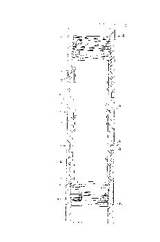
BRIEF DESCRIPTION OF THE DRAWINGS
~igure 1. depicts a vertical; section of a connector in accord
with the present invention.~igure 2. illustrates a thread form in accord with the present
invention.~igure 3. illustrates a thread form in accord with conventional
connections.~igure 4. depicts an embodiment of the present invention that
provides shoulder abutment upon makeup.~igure 5. depicts a fragmentary section of a connection in
accord with the present invention, when hand-tight.~igure 6. depicts the connection of Figure 5, at a make-up
position to effect a high efficiency connection.~igure 7. depicts the connection of Figure 5, at a make-up
position to effect a full strength connection.~igure 8. depicts a fragmentary section taken from Figure 4
of a pin thread of the present invention.~igure 9. depicts the pin thread of Figure 8 upon initial
contact with the mating box thread.~igure 10. depicts the box and pin threads of Figure 8 when
partially made up.~igure 11. depicts fully made up threads of the present invention.
~ --
~ 4 J '~
(18)
DETAILED DESCRIPTION OF THE INVENTION
Figure 1 depicts tubular connection shown generally at 20
comprising coupling 2 with tapered external threads 3 formed on
an upper portion and having like threads 4 formed on a lower
05 portion, so as to mate in sealing engagement with tapered
internal threads 6 and 7 formed within joints of non-upset tubing
8 and 9 respectively, to be connected.
Coupling 2 may comprise inner diameter 10, upper end surface
11 and lower end surface 12, said end surfaces not extending for
the full length of internal threads 6 and 7. Such a connection ,
as limited by the tension area resulting between the root
diameter of the last engaged thread as at 12, and the tubing
outer diameter, may provide an axial tension strength in excess
of three fourths of the pipe wall strength, effecting an
efficiency greater than 75~.
Should a connection of higher strength be required, coupling 2
may be formed with inner diameter as at 13, upper end surface as
at 14 and lower end surface as at 15. The coupling thereby
extending for substantially the full effective length of the
internal threads so as to provide a connection havinc~ an axial
strength substantially equal to the pipe wall strength to thereby
approach 100% efficiency.
Since typical tubing joints have lengths of sixty times or
more the lengths of couplings that connect them, the couplings
may be formed of material much stronger than the material the
joints are formed of without causing significant increase of cost
for the entire string. The use of higher strength material for
the coupling 2 provides a higher axial strength for the
connection 20 because, the strength of the coupling at neck
section 16 is increased and because, collapse resistance of the
pipe end as at 12 is increased to thereby increase the pullout
strength also. To further increase the pullout strength of the
connection, a thread form having a load bearing flank formed at
75 degrees with respect to the tubing axes as depicted in figure
2, may be used for the mating threads as opposed to the most
common thread form used on oilwell tubulars, depicted in Figure
3. The form of Figure 3 has a load bearing flanlc 25 which effects
an angle of 60 degrees with the tubing axis. Assuming an angle
of friction of 5 degrees, elementary vector analysis will show
that the form depi~ted in Figure 2 results in a pullout strength
2~ times that of Figure 3. Reduction of the flank angle still
further, can virtually elimimate tendency to pullout.
So as to ensure a seal diameter for the connection of least
diameter and therefore the least axial fluid load, the taper of
the external thread may be made slightly less than the taper of
the internal thread. Such a condition also allows maximum radial
. ( 19)
compression of the coupling as at end surface 12 adjacent pipe
wall as at 17 which may be formed thicker than the adjacent
coupling wall. Thus, upon makeup, end 12 will compress more than
wall 17 expands due to the difference in thickness, the moduli of
05 elasticity being considered substant;ally the same. Since
coupling 2 may be made of higher strength material than tubing
joints 8 or 9, the thickness may be dimensioned such that
stresses in walls at 12 and 17 are more nearly at the same
percentage of the yield strength of the materials of which the
members are formed.
When the taper of the external thread is made less than the
taper of the internal thread, initial contact between the two
occurs only at the small end as at 12 with the internal thread as
at 17. Vpon continued makeup, thread contact progresses toward
the larger end of the tapers to cause full engagement of the
threads as at 18. A slight amount of further makeup may cause a
predetermined magnitude of circumferential stress within the end
of the tubing joint as at 18 and thereby establish a position of
full makeup, so as to cause: compressive circumferential stresses
within end 12 to be at a first desired value, simultaneously with
tension circumferential stresses within the tubing joint wall
between 17 and 18 being at a second desired value, less in
magnitude than said first value. Said values may be set at the
same percentage of the unit yield strengths of the respective
materials to thereby effect a maximum strength for the
connection.
Connection 20 may comprise shoulder 18 formed on the end of
joint 9 and shoulder 19 formed on coupling 2 intermediate thread
4 and the outer diameter 21 of coupling 2. The mating threads may
be dimensioned so as to makeup as shown in Figure l or should
greater bending and compression strength or greater tortional
strength be desired, the mating threads may be dimensioned and
given closer tolerances so as to allow shoulders 18 and 19 to
abut upon makeup.
Figure 4 depicts a preferred bore configuration for the pin
end which can include minimum bore diameter extending to the pin
neck as at 13 and an outwardly tapering bore extending therefrom
to the pin end as at 53 which is sufficiently larger than bore 13
so as not to restrict bore 13 upon contraction of bore 53 upon
make-up of the connection. This preferred pin configuration may
be formed on each end of a coupling and it may also be formed on
the end of a pipe joint that has been swaged-down so as to
provide for bore 13 being smaller than the nominal pipe bore.
h ~ ~ 1 3 3
(20)
Figure 5 depicts a self-swaging tubular connection of the
present invention in the hand-tight position, comprising pipe
joint 60 formed with tapered pin thread 62 and pipe joint 61
having tapered box thread 63 formed for sealing cooperation
05 with pin thread 62 as later described. Box thread root diameter
64 at box face 65 iS preferably dimensioned such that the
radial width 67 of face 65 iS not less than radial thread depth
68 positioned between root diameter 64 and box thread crest
diameter 69 to prevent premature "jump-out" of the threads under
tensil loading. Likewise, it is preferred that radial width 70
of pin face 71 not be less than depth 68 for the same reason.
Box thread taper 72 should be slow enough to provide a
sufficient length of box thread 63 to prevent thread jumpout,
in cooperation with the thread load flank angle depicted in
15 Figure 2.
If the root diameter of the pin thread extends substantially
to the outer diameter of the pipe as at 73 as is well known in
the manufacture of collar type connections, and if the root
diameter of the box thread extends to the bore of the pipe as
20 at 74 taught by my U.S. Patent 4,813,717 in the line of priority
for the present application, then a high strength self-swaging
connection is now apparent.
For services where a full-strength connection is not
required and a maximum bore is desired, the connection may be
25 made-up as depicted in Figure 6. Upon such make-up, box wall
74 toward the large diameter end of thread engagement at face
65, iS thinner than adjacent pin wall 75 and therefore, box
wall 74 iS swaged outwardly by pin wall 75 to a predetermined
outer box diameter 79. Likewise, pin wall 76 toward the small
30 diameter end of thread engagement at face 71, iS thinner than
adjacent box wall 77 and pin wall 76 iS swaged in by box wall
77 to bore dimension 78 predetermined by both the box and pin
thread dimensions and the make-up position. At plane of equal
strength 80, axially positioned intermediate faces 65 and 71,
35 the outwardly swaging of box wall portion 81 iS substantially
equally to the inwardly swaging of pin wall 82. Because both
the box and pin wall are stressed triaxially when under
tension, it is an important feature of the present invention
that the degree of swaging in both walls decreases as the axial
40 load transfers from the mating thread. In further explanation,
wall 74 has received a greater degree of swaging and therefore
more tangential stress than wall 77 but does not carry as much
axial stress. Conversely, wall 77 can carry a higher axial
stress because it does not carry as much tangential stress.
i s ~ 3 3
(21)
For services where a full strength connection is required
and a smaller bore is acceptable, the connection may be made
up as depicted in Figure 7 whereupon, box outer diameter 90
has been swaged larger than diameter 79 and bore 91 has been
05 swaged smaller than bore 78. It is now apparent that pin wall
92 at the last engaged pin thread and box wall 93 at the last
engaged box thread are substantially the same as the nominal
pipe wall 94 to thereby effect a full-strength connection.
As taught by the above identified patent, the use of thread
forms having minimum thread depths and high load flank angles,
with respect to the tubular axis, facilitates the functions of
clearance and efficiency for flush and near-flush connections.
Such features may be used in combination with the present
invention to add new features such as, reducing the degree of
swaging required to attain a desired face width.
Upon review of these disclosures, it is now apparent that
an integral, full strength swaged connection can be formed
with plain end pipe without need for upsetting or swaging
prior to threading of the pipe ends. The portion of the swage
that is elastic equals the pipe diameter multiplied by the
yield stress, divided by the modulas of elasticity. The rest
of the swage is plastic. The present invention may be used for
a wide range of services and it may be desirable to vary the
amount of makeup to suit each service. One API standard allows
for 3% cold work of tubular goods, with regard to cold swaging
before threading, so that may be a practical limit of this
connection for such API services. An example within such a
limit is as follows: A 30 O.D. pipe with a 1" wall and a
radial thread depth of .133" requires a full strength
connection; 4x.133= .532" = the amount of swage required;
.532/30 = .0177 which is 1.77%; since 1.77% is less than 3%
then the connection would be acceptable.
Many tubular connections have only half as much strength
under axial compression loads as they have under axial
tension loads. A connection that is derated in compression
will have approximately that same derating in bending. So as
to adapt a connection in accord with the present invention to
any desired compression rating up to 100%, the stab flank angle (24)
depicted in Figure 2 may be adjusted as required without
departing from the spirit of the present invention.
The thread form depicted in Figure 2 may be used with the
present invention wherein angle 22 formed between load flank
30 and stab flank 24 is at least twice the angle of friction
between the box and pin materials, so as to prevent lockup of
the box and pin threads with each other due to the high
interface pressures generated by the radial forces necessary
to swage the connection during makeup.
1~ A ~ ~ 1 3 3
(22)
Figures 8-11 depict a fragmentary section of a preferred
embodiment of the thread form of the present invention through
four stages of makeup, enlarged from a connection as at 50 in
Figure 4. However, it should be understood that these features
05 may be used to advantage with other threaded connections without
departing from the spirit of my invention.
Pin member 31 formed with tapered pin threads shown generally
in Figure 8 at 32 comprise: tension flanks 33 and compression
flanks 34 formed at 83 degrees relative to tubular axis 35; root
10 36 formed with a radius tangent to flanks 33 and 34 as at 29 and
37 respectively; crest 38 formed with a radius of equal dimension
to the root radius, tangent to flanks 33 and 34 as at 39 and 40
respectively; included angle 41 dimensioned as fourteen degrees
between the surfaces of flanks 33 and 34.
Figure 9 depicts first contact of tapered pin threads 32 with
tapered box threads 42, formed complementary to pin threads 32
with no intended root gaps. After pin member 31 has been axially
positioned vertically without rotation into box member 45 such
that crests 38 will pass box thread crests 48 as along vertical
20 line 56 no further but will make circumferential contact with
crest 48 as at 47, it will thereby establish "stab position" of
the connection whereafter, weight of the pin member will serve
to maintain contact between the mating threads during makeup of
the connection. Box threads 42 also comprise tension flanks 44
25 and compression flanlcs 43 connected by roots and crests 46 and
48 respectively. A coating of API thread dope 49 is shown on pin
threads 32 so as to lubricate between the threads during malceup
and to seal between them as the threads become fully engaged.
Figure 10 depicts the threads at an intermediate stage of
30 makeup whereupon: pin thread flank 34 has gained an increased
area of contact as at 51 with box thread flank 43, the flanl~s
having slid along each other in response to rotation of the
tapered pin threads into the tapered box threads; dope having
been slowly squeezed radially from between flanl~s as at 55, to
35 the pin root gap as at 52 and toward the box root gap as at 54,
the slow flow allowing retention of solid particles between
flanks 33 and 34 as dope flows helically along root gaps 52 and
54. As makeup continues, some of the solid particles are carried
along root gaps until gaps 52 and 54 are reduced toward 0.006"
40 after which, the flow slows due to a buildup of back-pressure as
solid particles are then increasingly gripped between the roots
and crests. While grease flows momentarily around the particles
just before full mal~eup, the particles are firmly compacted as
in Figure 11 to seal the gaps. It should be noted that gap 55
45 between flanks 33 and 44 is less than one-fourth the width of
the root gaps at any stage of makeup, dictated by the 14 degree
included angle and complementary thread form.
133
(23)
Figure 11 depicts the position of full makeup of threads in
accord with the preferred embodiment with the axis positioned
vertically whereupon: the extremely high mechanical advantage
afforded by 83 degree flank angles has compressed solid particles
05 to thicknesses toward 0.0007" in gap 55 to support high end loads
and to 0.003" in gaps 52 and 54 to seal against extremely high
fluid pressures. Since the mating threads are formed complementary
to each other without large root gaps such as allowed for 8Rd
threads, the ratio of root-gaps/flank-gaps will be essentially
10 constant at 4.1 such that reasonable variations in formulation of
the dope may slightly affect final dimensions of the gaps, but will
not substantially affect strength, torque nor sealability.
Should the axis of the present invention be positioned
horizontally during assembly, then toward a 0.0007" thick layer
of solid particles may be trapped between both compression and
tension mating flanks at full makeup of the connection whereupon,
the root gaps may compress solid particles to a thickness such
as 0.006" to seal high fluid pressures when a sufficient helical
length of threads exist and the threads are held in best mating
20 contact against all service loads.
In comparison to the present invention, even if API 8Rd
threads had no intended root gap, their flank gap would equal
the root gap when assembled horizontally and would be twice the
root gap when assembled vertically. Such a large flank gap
during makeup allows a high rate of helical flow of dope from
between the flanks which reduces retention of solid particles
that are needed for best lubrication between the flanks. Even
at full makeup with the 8Rd flanks wedged, the root gaps may be
as large as 0.011" which allows a continued rheological fl~w of
dope out of the connection to cause lea~age, because the dope
cannot permanently seal such a gap. This explains one reason
why 8Rd threads cannot be expected to hold high pressures, and
the 60 degree flank angles allow mechanical loosening of the
connection upon the application of mechanical loads.
My thread form may be combined with features presented
earlier in the specification so as to provide low-torque threaded
connections for non-upset pipe joints with efficiencies as high
as 100%, that do not loosen or leak even when heavy shock loadings
are imposed, as may occur when they are used for drive-pipe.
Thus, it is now clear that the present invention provides
a thread form for high strength tubular connections that: will
not loosen in response to external loads; that will effect a
reliable long life seal between the threads; that can be easily
assembled and madeup with relatively low torque.
Although this low-torque, high-strength, reliable-sealing
thread form is of greatest advantage when used for drive-pipe,
it may also be used to advantage on connections depicted in
Figures 1, 4, 5, 6, 7, and others that may need such advantage.