Note: Descriptions are shown in the official language in which they were submitted.
CA 02111934 2004-07-20
SCANNER MODULE FOR SYMBOL SCANNING SYSTEM
I5
B.ACKaROU~ID OF TH8 INVENTION
A. tai~ld of the Iavention
The present invention relates to scanning systems which
"read" indicia, for example, barcode symbols, having parts with
different light reflectivities and, in particular, to a scanner
module for directing a beam of light in a predetermined scanning
pattern at a barcode symbol and directing light reflected from the
barcode symbol to an optical detector.
- I -
B. Discussion ofthe R~latsd Art
Various optical readers and optical scanning systems have
previously been developed for reading barcode symbols appearing on
a label, or on the surface of an article. The barcode symbol
itself is a coded pattern of indicia. Generally, scanning systems
electro-optically transform the graphic indicia.af.the symbols
into electrical signals which are decoded into alphanumeric char-
acters. The resulting characters describe the-article and/or some
characteristic of the article to. which the symbol-is attached.
Such characters typically comprise input data to a data processing
system for applications in point-of-sale processing, inventory
control, and the like. ~-
As used in this specification and in the following claims,
the terms "symbol," "barcode," and "barcode symbol" are used to
denote a pattern of variable-width bars separated by variable
width spaces. The foregoing terms are intended to be broadly
construed to cover many specific forms of one- and two-dimensional
patterns including alphanumeric characters, as well as, bars and
spaces.
The specific arrangement of bars or elements in a symbol
defines the character represented according to a set of rules and
definitions specified by the code. This is called the "symbology"
of the code. The relative size of the bars and spaces is
determined by the type of code used, as is the actual size of the
bars and spaces. The number of characters per inch represented by
the barcvde symbol is referred to as the density of the symbol.
- 2 -
CA 02111934 2004-07-20
To encode a desired sequence of characters; a collection of
element arrangements are concatenated to form the complete symbol,
with each character being represented by its own corresponding
group of elements. In some symbologies, a unique "start" and
"stop" character is used to indicate where the barcode symbol
begins and ends. A number of different barcode symbologies
presently exist. These symbologies include one-dimensional codes
such as UPC/EAN, Code 39, Code 128, Codabar, and Interleaved 2
of 5.
In order to increase the amount of data that can be
represented or stored on a given amount of symbol surface area,
several new symbologies have been developed. One new code
standard, Code 49, introduced a two-dimensional-concept of
stacking rows of characters vertically instead of extending
sY'~ols bars horizontally. That is, there are several rows of bar
and space patterns, instead of one long row. The structure of
Code 49 is described in U.S. Patent No. 4,794,23-9. Another two-
dimensional code structure known as PDF417 is described in U.S.
Patent No. 5,304,786.
Scanning systems have been disclosed, for example, in U.S.
Patents Nos. 4,251,798; 4,369,361; 4,387,297; 4,409,470;
4,760,248; 4,896,026, all of which have been assigned to the
assignee of the present invention. As disclosed in some of the
above patents, and particularly in U.S. Patent 4,409,470, one
existing scanning system comprises a hand-held, portable laser
- 3 -
' 211193.
scanning head. The hand-held scanning system is configured to
allow a user to manually aim a light beam emanating from the head
at a target symbol.
These scanning systems generally include a light source
consisting of a gas laser or semiconductor laser. The use of
semiconductor devices as the light source in scanning systems is
especially desirable because of their small size, low cost and low
power requirements. The laser beam is optically manipulated,
typically by a focusing optical assembly, to form a beam spot
having a certain size at a predetermined target location.
Preferably, the cross section of the beam spot at the target
location approximates the minimum width between symbol regions of
different light reflectivity, i.e., the bars and spaces.
In conventional scanning systems, the light beam is directed
by lens or similar optical components along a light path toward a
target symbol. The scanner operates by repetitively scanning the
light beam in a line or a series of lines across the target symbol
by movement of a scanning component such as a mirror disposed in
the path of the light beam. The scanning component may sweep the
beam spot across the symbol, trace a scan line across and beyond
the boundaries of the symbol, and/or scan a predetermined field of
view.
Scanning systems also include a sensor or photodetector which
functions to detect light reflected or scattered from the symbol.
The photodetector or sensor is positioned in the scanner in an
optical path so that it has a field of view which extends at least
across and slightly beyond the boundaries of the symbol. A
- 4 -
2111934
portion of the light beam reflected from the symbol is detected
and converted into an analog electrical signal. The pulse-width
modulated digitized signal ~fsma the~ a~igiti~~aer is decoded, based
upon the specific symbology used for the symbol, into a binary
data representation of the data encoded in the symbol. The binary
data may then be subsequently decoded into the alphanumeric
characters represented by the symbol.
Overall performance of a scanning system in reading symbols
is a function of the optical capabilities of the scanning
mechanism in directing a light beam at a target symbol and
resolving the reflected light, and a function of the electronic
subsystems which convert and process the information contained in
the reflected light. A measure of the overall performance of a
barcode symbol scanning system is its ability to resolve the
narrowest elements of a barcode symbol and its ability to decode
symbols located perhaps hundreds of inches away from the scanning
system.
An important component of any scanning system is the scanner
module which directs a well-defined light beam in a predetermined
beam pattern at the barcode symbol and directs the reflected light
from the barcode symbol to a suitable photodetector. The beam
pattern that scans the barcode symbol can take a variety of forms,
such as repeated line scan, standard raster scan, jittered raster
scan, fishbone, petal, etc. These beam patterns are generated by
controlled motions of one or more optical elements in the beam
path. Typically, the optical element includes a mirror that is
driven by some form of scanning motor to periodically deflect the
- 5 -
CA 02111934 2004-07-20
beam through the desired beam scanning pattern. For a repeated
line scan beam pattern;,a polygonal mirror undirectionally rotated
by a simple motor can be utilized. For more complex beam
patterns, more involved drive mechanisms ate required.
The frequency at which the beam pattern is executed is also
an important consideration. The more times--a barcode symbol can
be scanned in a given time period, the chances of obtaining a
valid read of the barcode symbol are increased. This is
particularly important when the barcode symbols are borne by
moving objects, such as packages travelling on a conveyor belt.
Many applications call for a handheld scanning system, where
a user aims a light beam at the barcode symbol, and the beam
executes a scan pattern to read the barcode symbol. For such
applications, the scanner module must be compact in order to be
accommodated in a handheld package which may be pistol-shaped.
Moreover, such scanners must be lightweight and structurally
robust to Withstand physical shock resulting from rough handling.
It is also desirable that the scanner module consume minimal power
during operation.
S~ARY OF THE INVENTION
It is accordingly an object of the present invention to
provide an improved optical scanner module for utilization in a
scanning system for reading a data-encoded symbol. The optical
scanner of the present invention is compact, lightweight, durable
and efficient in construct and operation, and thus is ideally
suited for portable handheld applications.
- 6 -
2111934
Thus, in accordance with the present invention, an optical
element and a permanent magnet are mounted to an elongated flex
element which, in turn, is mounted to position the optical element
in the optical path of a light beam aimed at the data-encoded
symbol. An electromagnetic coil, to which scanning control
signals in the form of AC drive current is applied, produces a
magnetic field to interact with the magnetic field of the
permanent magnet to cause flexure of the flex element and thus
controlled oscillatory beam scanning motion of the optical element
in one direction. -
To produce bidirectional scanning motion of the optical
element, the flex element, permanent magn~rt, and optical element
assembly is, in turn, mounted by at least one additional flex
element to accommodate oscillatory motion of the assembly in a
second direction, preferably orthogonal to the one direction. In
accordance with the present invention, bidirectional oscillatory
motion of the optical element is induced by the interaction of
magnetic fields generated by a single permanent magnet and a
single electromagnetic coil. Alternative embodiments of the
invention provide two permanent magnet and electromagnetic coil
sets to drive the optical element in two directions of oscillatory
motion.
In a further embodiment of the invention, the magnetic fields
of two electromagnetic coils interact with the magnetic field of a
single permanent magnet to produce bidirectional oscillations of
the optical element.
2,~ 1 1 93 ~,
Additional features and advantages of the present invention
will be set forth in the description which follows, and in part
will be apparent from the description, or may be learned from
practice of the invention. The objectives and advantages of the
invention will be realized and attained by the apparatus
particularly pointed out in the written description and claims
hereof, as well as the appended drawings.
It is to be understood that both the foregoing-general
description and the following detailed description are exemplary
and explanatory and are intended to provide further explanation of
the invention as claimed. -
The accompanying drawings are included to. provide a further
understanding of the invention and are incorporated .in and
constitute a part of this specification, illustrate several
e~odiments of the invention and, together with the description,
serve to explain the principles of the invention.
BRIEh DESCRIPTION Og THE DRA~tINC~B
For a full understanding of the present invention, reference
may be had to the following Detailed Description taken in
conjunction with the accompanying drawings, in which:
Fig. 1 is a schematic diagram of a handheld optical scanning
system for reading a barcode symbol and incorporating a scanner
module of the present invention;
Figs. 2 and 3 are front and side views, respectively, of a
two-directional scanner module constructed in accordance with one
embodiment of the present invention;
_ g _
y 21 1 1 93 4
Fig. 4 is a perspective view of a two-directional scanner
module constructed in accordance with a second embodiment of the
present invention;
Fig. 5 is a longitudinal sectional view of a two-directional
scanner module constructed in accordance with a.third embodiment
of the present invention;
Fig. 6 is a perspective view of a two-directional scanner
module constructed in accordance with a fourth embodiment of the
invention;
Fig. 7 is a perspective view of a two-directional scanner
module constructed in accordance with a fifth embodiment of the
invention;
Fig. 8 is a perspective view of a two-directional scanner
module constructed in accordance with a sixth embodiment of the
Present invention;
Fig. 9 is a perspective view of a two-directional scanner
module constructed in accordance with a seventh embodiment of the
invention;
Fig. 10 is a longitudinal sectional view of a one-directional
scanner module constructed in accordance with an eight embodiment
of the present invention;
Fig. 11 is a longitudinal sectional view of a one-directional
scanner module constructed in accordance with a ninth embodiment
of the invention; and
Figs. 12, 13 and 14 are plan, front and side views,
respectively, of a two-directional scanner module constructed in
accordance with a tenth embodiment of the present invention.
- 9 -
'~ 21 1 1 9 3 ,~
Like reference numerals refer to correspon(iing parts
throughout the several views of the drawings.
DLTAILED DESCRIPTI03~1
Figure 1 illustrates a portable pistol-shaped scanning
system, generally indicated at 20, to which the scanner module of
the present invention is particularly suited. Scanning system 20
has a pistol-grip type handle 21, and a manually-actuated trigger
switch 22 which allows the user to activate a light beam 23 after
the user has positioned the scanning system to a point on a symbol
24. A lightweight plastic housing 25 contains a laser light
source 26, detector 27, optics and signal processing circuitry 28,
and power source or battery 29.
A light-transmissive window 30 in the front end of housing 25
allows outgoing light beam 23 to exit. and incoming reflected light
31 to enter. Scanning system 20 is designed to be aimed at
barcode symbol 24 by a user from a position in which the scanning
system is spaced from the symbol or moving across the symbol.
Typically, this type of handheld scanning system is specified to
operate at a range of greater than several inches. Scanning
system 20 may also function as a portable computer terminal, and
in such embodiments includes a keyboard 32 and a display 33, such
as described in the previously noted U.S. Patent No. 4,409,470.
As further depicted in Figure l, a beam splitter 34, or a
suitable multiple lens system, may be used to focus the light beam
into a scanning spot in an appropriate reference plane at the
predetermined location. Light source 26, such as a semiconductor
laser diode, is positioned to introduce a light beam along the
- 10 -
21 1193 4
axis of a lens 35, and the beam passes through partially-silvered,
beam splitting mirror 34 and other lenses or beam-shaping
structure as needed. The beam is reflected by an oscillating
mirror 36 of a scanner module of the present invention, which is
generally indicated at 38. The scanner module is energized when
trigger 22 is pulled. If the light produced by source 26 is
marginally visible, an aiming light may be included in the optical
system. The aiming light, if needed, produces a visible-light
spot which may be fixed or scanned like the laser beam. A user
employs this visible light to aim the scanning system at the
symbol before pulling the trigger.
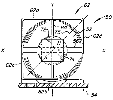
In the embodiment of the invention seen in Figs. 2 and 3, a
scanner module, generally indicated at 50, includes an
electromagnetic coil 52 mounted in vertical orientation on a
suitable stationary base, such as a circuit board 54, to orient a
horizontal magnetic axis 55 coincident with the coil centerline.
A horizontal flex element 56 is affixed at opposite ends to
standoff mounts 58 attached at diametrically opposed locations on
coil 52. This mounting of flex element 56 is such as to place it
in a taut condition. The taut flex element may be formed of any
suitable strip material, such as polyamide or polyester plastic
film. KAPTONe and MYLAR~ plastic films marketed by Dupont
Corporation are highly suitable materials for taut band element
56.
Affixed to taut band element 56 at a location centered on
magnetic axis 55 is the lower end of a bracket 60, whose upper end
is fastened to an upper horizontal side 62a of a generally
- 11 -
CA 02111934 2004-07-20
rectangular frame 62. This frame, which is mounted in suspension
by bracket 60, includes a short, lower horizontal side 62b
integrally joined with side 62a by a full length left vertical
side 62c and a short right vertical side 62d hanging from the
right end of full length upper side 62a. A vertical flex element
64 is secured at its upper end to a mid-length point of frame side
62a and at its lower end to~frame side 62b. Frame 62 is formed of
a suitable metallic spring stock, such as beryllium copper, such
that it can stretch flex element 64 to a taut condition. Suitable
~terials for flex element 64 are beryllium copper and steel wire.
As seen in Fig. 3, taut band element 56 also cantilever mounts,
via bracket 60, a secondary L-shaped bracket 66 having a vertical
segment hanging rearwardly of coil 52 and serving to mount a
mass 68 for counter-balancing the mass of the frame and a mirror-
~gnet assembly to be described. By proper selection of mass 68,
torsional forces on taut band element 56 can be reduced
essentially to zero while the scanning module is in a quiescent
state.
Still referring to Figs. 2 and 3, a carrier 70 is affixed to
taut wire element 64 in a position centered on magnetic axis 55 of
coil 52. This carrier mounts a mirror 72 forwardly of taut wire
element 24 and a permanent magnet 74 rearwardly of the taut wire
element. The permanent magnet is in the form of a cube and is
polarized along a magnetic axis 75 oriented at an oblique angle,
e~g~ 45°, with respect to indicated X and Y axes. Thus, for
example, permanent magnet 74 is polarized such that north pole N
- 12 -
2111934:
is generally located at the upper right corner end south pole S at
the lower left corner of the magnet cube, as seen in Fig. 2.
It is seen from the foregoing description that mirror 72 can
oscillate about the Y axis through taut wire element 64 with
torsional flexure of this flex element to deflect a laser beam in
an X scanning direction. Also, the mirror can oscillate about the
X axis through taut band element 56 with torsional flexure of this
flex element to deflect the laser beam in a Y scanning direction.
With the magnetic axis 75 of the single permanent magnet 74
obliquely oriented, X and Y mirror scanning motions can be driven
by energizing of the single electromagnetic coil 52.
In accordance with a feature of the invention, by utilizing a
flex element in the form of taut wire element 64 and controlling
the mass of the mirror-magnet assembly, the resonant frequency for
X scanning motion can be established at a relative high frequency,
e.g., 500 Hz. Then, by utilizing a flex element in the form of
taut band element 56 with the considerably greater mass supported
by this flex element, as compared to taut wire element 64, a
resonant frequency for Y scanning motion can be established at a
considerably lower frequency, e.g., 20 Hz. By virtue of this wide
separation between resonant frequencies, if the electromagnetic
coil is energized with an AC current of 500 Hz, the interaction of
the magnetic fields of the coil and permanent magnet 74 produces
mirror oscillations essentially only about the Y axis and thus
beam scanning motion only in the X direction. On the other hand,
when the coil is energized with an AC current of 20 Hz, the
interaction of the coil and magnet fields produces mirror
- 13 -
CA 02111934 2004-07-20
oscillation essentially only about the X axis tF~rough taut band
element_56, and thus beam scanning motion only in the Y direction.
However, when electromagnetic coil 52 is driven with superimposed
500 Hz and 20 Hz AC currents, mirror oscillates about both the X
and Y axes to produce beam scanning motion components in both the
X and Y directions. Such current superimposition can be achieved
by producing a 20 Hz amplitude modulation of a 500 Hz AC drive
current. Variable modulation of this drive current in amplitude
and/or frequency can then produce a variety of laser beam scan
patterns, including those patterns illustrated in U.S. Patent
No. 5,478,997, cited above.
The embodiment of the invention seen in Fig. 4 comprises a
two-directional scanner module, generally indicated at 80, which
includes an electromagnetic coil 82 mounted to stationary base 84
in vertical orientation to establish a horizontal magnetic axis
85. A ring 86 is mounted to the electromagnetic coil by a pair of
flex elements in the form of leaf springs 88 at diametrically
opposed three and nine o'clock positions. These Leaf springs lie
in a horizontal plane and thus are flexible in the vertical or Y
direction. A vertically oriented flex element 90, in the form of
a band of plastic film material or a wire, as utilized in the
embodiment of Figs. 2 and 3, is fixed at one end to ring 86 at a
twelve o'clock position and at its other end to the ring at a six
o'clock position. The band is stretched tight such as to function
as a taut flex element.
- 14 -
_
A mirror 92 is mounted to the front side of taut flex element
90, and a permanent magnet 94 is mounted to the back side of the
taut band element. The mounting of the mirror and permanent
magnet is centered on horizontal magnetic axis 85. Permanent
magnet 94 is magnetized in the horizontal direction to establish a
magnetic axis 95 which is normal to the magnetic axis 85 of
electromagnetic coil 82.
When the electromagnetic coil is energized with an AC
current, the magnetic fields of the electromagnetic coil and
permanent magnet interact to produce forces causing the mirror-
magnet assembly to oscillate in the horizontal direction as taut
band element 90 flexes in torsion. A laser beam impinging on the
mirror is thus deflected in a horizontal or X scanning direction.
The same magnetically induced forces that generate X direction
scanning motion attempt to produce a similar motion of ring 86.
Due to the stiffness of the leaf spring suspension mounting of the
ring, the horizontal component of the magnetically induced forces
can not produce horizontal oscillation of the zing. However,
tensile and compressive stresses are induced in leaf springs 88,
which produce vertical force components effective to create a
vertical moment causing the ring to move in the vertical
direction. The frequency of the up and down oscillation in the Y
direction is determined by the mass of the ring assembly (ring,
taut flex element, mirror and permanent magnet) and
characteristics of the leaf springs, e.g., elasticity, dimensions,
etc.
- 15 -
2111934;
It is thus seen that, by virtue of the flekible mounting of
the ring assembly to accommodate vertical motion, scanner module
80 is capable of bidirectional, e.g., X and Y, oscillation to
produce raster scanning of a laser beam deflected by mirror 92.
Permanent magnet 94 is illustrated as having a cubic shape with a
minimized horizontal dimension to reduce its inertial moment about
the Y axis. Thus horizontal oscillations of the mirror can be
induced with less drive current power applied to the electro-
magnetic cord.
In the embodiment of the invention seen in Fig. 5, a scanner
module, generally indicated at 100, includes an electromagnetic
coil 102 vertically mounted to a stationary base 104 to establish
a horizontally oriented magnetic axis 105. As in scanner module
80 of Fig. 4, scanner module 100 utilizes an ring assembly
including a ring 106 mounting a vertical taut band element 108
which, in turn, mounts in back-to-back relation a forward mirror
110 and a rearward permanent magnet 112 in centered relation with
magnetic axis 105. Again, permanent magnet 112 is polarized in
the horizontal direction to orient a magnetic axis (not shown)
orthogonal to magnetic axis 105. As a modification to scanner
module 80 of Fig. 4, scanner module 100 utilizes a single flexible
member to mount the ring assembly. Thus, as seen in Fig. 5, a
flex member 114, flexible in the vertical direction and stiff in
the horizontal direction, is affixed at a rearward end to an
upright extension 115 of base 114 located to the rearward side of
electromagnetic coil 102. Flex member 114 extends forwardly
through the open center of the electromagnetic coil 102 in aligned
- 16 -
2111934
relation with magnetic axis 105 to a frontal end to which the ring
assembly is mounted by way of bracketing 116.
As in the case of scanner module 80 of Fig. 4, AC current
drive of electromagnetic coil 102 of scanner module 100 in Fig. 4
produces horizontal oscillation of mirror 110 with torsional
flexure of taut band element 108 and the ring assembly oscillates
in the vertical direction on the cantilever mounting provided by
central flex member 114. Thus, scanner module 110 also provides
bidirectional, X and Y raster scanning motion of a laser beam
utilizing a single electromagnetic coil and a single permanent
magnet.
Rather than utilizing an oscillating mirror to produce laser
beam scanning, as in the scanner module embodiments described
above, laser beam scanning can be effected utilizing an
oscillating lens. Thus, as seen in Fig. 6, a scanner module,
generally indicated at 120, utilizes the same ring assembly
suspension mounting approach of scanner module 80 of Fig. 4.
Thus, ring 86 is mounted to vertically oriented electromagnetic
coil 82 by a pair of leaf springs 88 at the three and nine o'clock
Positions. The ring, in turn, mounts a lens 122 whose optical
center is aligned with the magnetic axis 85 of electromagnetic
coil 82. A laser 124 is positioned to emit a beam along magnetic
axis 85 and through lens 122. So as not to obstruct the laser
beam, the lens is mounted along its peripheral edge to a ring-
shaped permanent magnet 126 and the magnet, in turn, is mounted to
ring 86 by a pair of vertically aligned, short, taut band elements
130a and 130b. Taut band element 130a is connected between the
- 17 -
CA 02111934 2004-07-20 -
twelve o'clock positions of the ring and ring magnet, and taut
band element 130b is connected between the six o'clock positions
of the ring and ring magnet. The permanent ring magnet is
polarized in the horizontal direction, as illustrated, to
establish a magnetic axis 95 orthogonal to magnetic axis 85. AC
drive current applied to the electromagnetic coil produces X and Y
directional oscillations of lens 122, as in the case of mirror 82
in Fig. 4, to achieve pre-objective scanning of the laser beam in
X and Y directions.
Two-directional scanning is also achieved by the scanner
module, generally. indicated at 140 in Fig. 7. In this embodiment
of the invention, an electromagnetic coil 82 is again mounted in
upright orientation to a stationary base 84. As in the case of
.scanner module 80 (Fig. 4), a ring assembly is utilized, composed
of a ring 86 mounting a vertically oriented taut band element 90,
r~ith a frontal mirror 92 and rearovard permanent magnet 94 centrally
mounted to the taut band element. However in this embodiment, the
ring assembly is mounted in vertical orientation directly to base
84 by a single, vertical flex member 142 which allows the ring
assembly to rock fore and aft generally along magnetic axis 85 of
the electromagnetic coil 82. This rocking motion is seen to
produce oscillatory motion of mirror 92 in the vertical or Y
direction in the manner provided by the horizontal flex mounting
elements of Figs. 4-6.
To induce this vertical oscillation of mirror 92, a second
stationary electromagnetic coil 144 is situated within the central
opening of electromagnetic coil 82 with its magnetic axis 145
- 18 -
21 1 1 9 3.4~
oriented perpendicular to axis 85 of coil 82. This magnetic axis
145 is parallel to magnetic axis 95 of permanent magnet 94. Thus,
when electromagnetic coil 144 is driven by an AC current,
permanent magnet 94 is alternately attracted toward and repelled
from the coil 144. The ring assembly is thus rocked fore and aft
on flex mount 142, and vertical components of oscillation of
mirror 92 are produced. As in the case of the embodiments of
Figs. 4-6, horizontal or X direction oscillation of the mirror is
induced by AC current energization of electromagnetic coil 82.
It will be appreciated that flex mount 142 may be implemented
as an extension of taut band element 90. Also, electromagnetic
coil 144 may be provided as a continuation of the winding for
electromagnetic coil 82, which is wound on a horizontal cross
member of a bobbin for coil 82. As an additional feature, scanner
module 140 of Fig. 7 possesses two resonances for oscillations in
the horizontal or X direction. Torsional oscillation on taut band
element 90 will resonate at a high frequency, while torsional
oscillation on flex member 142 will resonant at a low frequency.
Turning to Fig. 8, another embodiment of the invention is
illustrated in the form of a scanner module, generally indicated
at 150, which includes a cylinder 152, formed of a non-magnetic
material, which is provided with horizontally opposed slits 153
through with an elongated flex element 154 extends. This flex
element, which is in the form of a strip of flexible material,
such as spring steel, has opposed ends fixedly mounted between
bobbins 158a and 160a on which an X deflection electromagnetic
- 19 -
CA 02111934 2004-07-20
coil 158 and a Y deflection electromagnetib coil 160 are
respectively wound.
Cylinder 152 is also formed with forwardly located,
vertically opposed slits I61 in which ends of an elongated
vertical flex element 162 are captured. This flex element 162 is
typically formed of the same material as flex element 156. A
mirror 163 is mounted to the front side and a permanent magnet 164
is mounted to the back side of flex element 162 in positions
centered on the centerline of cylinder 152, which coincides with
the magnetic axes of electromagnetic coils 158 and 160. A second,
vertically oriented permanent magnet 166 is mounted to the
rearward end of cylinder 152. As illustrated, permanent magnet.
166 is polarized in the vertical direction and is positioned such
that its magnetic field, having a vertically oriented axis, can
interact with the magnetic field produced by electromagnetic coil
160, whose axis is horizontal and thus orthogonal thereto.
Permanent magnet 164 is polarized in the horizontal direction and
is positioned such that its magnetic field can interact with the
orthogonally related magnetic field produced by electromagnetic
2p coil 158.
By virtue of this construction of scanner module 150, it is
seen that AC drive current applied to electromagnetic coil 158
produces a magnetic field that interacts with the magnetic field
of permanent magnet 164 to produce horizontal oscillations of
mirror 162, and thus laser beam scanning in the X direction, as
vertical flex element 162 flexes in torsion. AC current drive of
electromagnetic coil 160 then produces a magnetic field which
- 20 -
2111934~~
interacts with the magnetic field of permanent magnet 166 to
produce vertical oscillations of the mirror and laser beam
scanning in the Y direction as horizontal flex element 154 flexes
in torsion. Thus, a bidirectional raster scan of the laser beam
is achieved. Since the mass supported by horizontal flex element
154 is greater that the. mass supported by vertical flex element
162, the resonant frequency of horizontal oscillations is higher
than the resonant frequency of vertical oscillations. It will be
appreciated that, by providing separate horizontal and vertical
coil-magnet sets, X and Y directional scanning can be readily
controlled to create a wide variety of laser beam scan patterns.
In the embodiment of the invention seen in Fig. 9, a scanner
module, generally indicated at 170, includes a taut band element
172 affixed in vertical orientation to the forward end of a bobbin
173 of an electromagnetic coil 174. Affixed to the front side of
this taut band element is a mirror 176, and a permanent magnet 178
is affixed to the back side thereof. An elongated flex member 180
extends through horizontally opposed slits 181 in bobbin 173 with
opposite ends anchored to the front ends 182a of longitudinally
extending arms 182 of a U-shaped, stationary bracket having a
transverse base 184 interconnecting the rearward ends of the arms.
A permanent magnet 186 is secured to the bracket base and is
polarized in the vertical direction to establish a vertically
oriented magnetic axis. Permanent magnet 178 is polarized in a
transverse or horizontal direction to establish a magnetic axis
that is orthogonal to both magnetic axes of permanent magnet 186
and to the longitudinal magnetic axis 175 of electromagnetic coil
- 21 -
21'~ 1 93 ~.
174. The mounting position of the mirror-magnet assembly on taut
band element 172 is centered on electromagnetic coil axis 175.
In operation, upon AC current energization of electromagnetic
coil 174, mirror 176 is oscillated in the horizontal direction as
the result of the interaction of the orthogonally related magnetic
fields of the electromagnetic coil and permanent magnet 178. This
oscillation in the X direction is accommodated by torsional
flexure of taut band element 172. Concurrently, the bobbin
mounted mirror oscillates in the vertical direction by virtue of
the interaction of the orthogonally related magnetic fields of the
electromagnetic coil and permanent magnet 186, as permitted by
torsional flexure of flex member 180. Thus bidirectional laser
beam scanning motion is produced utilizing a pair of permanent
magnets and a single electromagnetic coil. Again resonance for
oscillation in the X direction is at a higher frequency than the
resonant frequency for oscillation in the Y direction. It will be
appreciated that the coil winding on bobbin 122 may be a split
coil with forward and rearward coil portions driven separately to
produce the desired horizontal and vertical components of
oscillatory mirror motion for a variety of bidirectional scan
patterns executed by a laser beam.
In the embodiments of the invention described above, the
electromagnetic coils are of the air core type. In the scanner
module embodiments 200 and 202 illustrated in Figs. 10 and 11,
respectively, an electromagnetic coil 204 is wound on a metallic
core 206 of high magnetic permeability. The core is mounted to or
integrally formed with a circular base 208 of like material. A
- 22 -
2111934
cylinder 210 of magnetically permeable metal is'joined at its
rearward end to base 208 in coaxial relation with core 206. An
elongated flex member 212 in the form of a taut band or taut wire
element is affixed to span the forward end of cylinder 210 from
twelve to six o'clock positions. Affixed to this vertical flex
element is a frontal mirror 214 and a rearward permanent magnet
216 in positions centered on centerline 207 of core 206. The
permanent magnet is polarized in a horizontal direction into and
out of the drawing sheet.
It is seen that a closed magnetic path is provided to
concentrate the magnetic filed generated by AC current
energization of electromagnetic coil 204 in the air gaps between
the forward ends of the core and cylinder. The coupling
efficiency of the magnetic fields of.the permanent magnet and
electromagnetic core is thus enhanced. The interaction of these
magnetic fields is increased to generate enhanced torsional forces
producing horizontal or X direction oscillations of mirror 214.
Consequently, scanner modules 200 and 202 require less power to
oscillate the mirror, a significant advantage in portable
aPPlications. Fig. 11 illustrates that the forward end of
cylinder 210 may be turned radially inward to present an annular
pole piece 211 in closer proximity to permanent magnet 216 and
core 206. Also, Fig. 11 illustrates that flex member 212 may be
mounted to a ring 215, of a rigid plastic for example, and ring
then affixed to the front end of cylinder 210. This standoff
mounting provides clearance between the flex member and pole piece
211, as well as simplifying manufacturing and assembly procedures.
- 23 -
21 11-93 4
In the embodiment of the invention seen in'Figs. 12-14, a
scanner module, generally indicated at 220, includes a stationary
dual bobbin 222 on which are wound a forward electromagnetic coil
224 and a rearward electromagnetic coil 226. The magnetic axes of
these coils are indicated at 225. A pair of transversely aligned,
fixed mounting posts 228, positioned in flanking relation with
bobbin 222, respectively serve to anchor the rearward ends of a
pair of flex elements 230 via clamping screws 232. The front ends
of these flex elements are clamped between horizontally turned
inner foot portions of vertically oriented pairs of Z-shaped front
frame members 234, with each vertical pair being interconnected by
upper and lower cross frame members 236 as seen in Fig. 13.
Horizontally turned outer foot positions of front frame members
234 are secured, as indicated at 237; to U-shaped frame members
having forwardly extending upper and lower arms 238 joined by
vertically oriented, rear frame members 240. The transversely
spaced rear frame members are interconnected by a cross frame
member 242 at a position vertically centered with magnetic axis
225.
A holder 244 is provided to carry a mirror 246 at a front end
and a permanent magnet 248 at a rear end. As best seen in Fig.
13, a first vertically oriented flex element 250 is anchored at
its upper end to upper cross frame member 236 and anchored at its
lower end to the upper side of holder 244. A second vertically
oriented flex element 252 is anchored at its upper end to the
lower side of holder 244 and anchored at its lower end to lower
cross frame 236. The flex elements 250 and 252 mount holder 244
- 24 -
2111934
such that mirror 246 and permanent magnet 248 a're centered on
magnetic axis 225. A second permanent magnet 254 is mounted to
rear cross frame member 242 also in a position centered on
magnetic axis 225. The weight of permanent magnet 254 is selected
to counterbalance the weight of the mirror-magnet holder assembly
and the frame, such that the components are cantilever mounted to
posts 228 in the balanced positions seen in Fig. 14. Also, the U-
shaped frames and their frontal interconnecting Z-shaped frame
members are formed of spring metal strips effective to stretch
horizontal flex elements 230 and vertical flex elements 250 and
252 into taut conditions.
In operation, when electromagnetic coil 224 is driven by an
AC current, its magnetic field interacts with the magnetic field
of permanent magnet 248, polarized in the horizontal direction, to
produce oscillations of mirror 246 in the horizontal or X
direction as flex elements 250 and 252 flex in torsion.
Energization of electromagnetic coil 226 with AC current generates
a magnetic field which interacts with the magnetic field of
permanent magnet 254, polarized in the vertical direction, to
produce seesaw or rocking motion of the entire frame generally in
the vertical or Y direction. Mirror 246 thus also rocks in
vertical oscillation to deflect an incident laser beam in the Y
scanning direction. Scanner module 220 thus operates as a
bidirectional scanner module capable of providing complex laser
beam raster scanning.
- 25 -
2111~934~
It is well understood that, because a laser beam 260
(illustrated in Fig. 14) must necessarily strike mirror 246 at an
oblique angle to avoid reflection back on itself, a beam scan line
in the X direction has a slight degree of curvature. The scanner
module 220 is capable of correcting scan line curvature. As seen
in Fig. 13, the dimensions dl and d2 of vertical flex elements 252
and 250, respectively, are differentially selected to compensate
the mirror motions near the extremes of its horizontal
oscillations and thus correct for X scan line curvature.
It will be apparent to those skilled in the art that various
modifications and variations can be made in the optical scanner
module of the present invention without departing from the spirit
or scope of the invention. Thus, it is intended that the present
invention cover the modifications and. variations of this invention
provided they come within the scope of the appended claims and
their equivalents.
- 26 -