Note: Descriptions are shown in the official language in which they were submitted.
J
DOCKET NO. 2548
CONTAINED QUENCH SYSTEM FOR
CONTROLLED COOLING OF CONTINUOUS WEB
8ackground Of The Invention
This invention relates to a method and apparatus for
continuously cooling a moving web, and particularly to a
method and apparatus for strip casting of metals in which an;
endless belt is cooled in a manner to improve the quality of
the metal cast.
The continuous casting of thin metal strip has been
employed with only limited success. By and large, prior
processes for the continuous casting of metal strip have been
limited to a relatively small number of alloys and products.
It has been found that as the alloy content of various metals
are increaæed, as-cast surface quality deteriorates. As a
result, many alloys must be fabricated using ingot methods.
In the case of aluminum, relatively pure aluminum
product such as foil can be continuously strip cast on a
commercial basis. ~uilding products can likewise be
continuously strip cast, principally because surface quality
in the case of such building products is less critical than in
other aluminum products, such as can stock~ However, as the
alloy content of aluminum is increased, surface quality
problems appear, and strip casting has generally been
unsuitable for use in making many aluminum alloy products.
A number of strip casting machines have been
proposed in the prior art. One conventional device is a twin
belt strip casting machine, but such machines have not
achieved widespread acceptance in the casting of many metals,
and particularly metal alloys with wide freezing ranges. In
such twin belt strip casting equipment, two moving belts are
. ,, . ,.,- . , - ,, ~ , . . .
,.,,; . . :
,.~, , - .
!,' j. , , , ' ~ , ` , , : ,
~ .
,~, , ~ :
~.''" .. : ' ' ~
: , ~ . ,,
provided which define between them a moving mold for the metal
to be cast. Cooling of the belts is typically effected by
contacting a cooling fluid with the side of the belt opposite
the side in contact with the molten metal~ AS a result, the
belt is subjected to extremely high thermal gradients, wlth
molten metal in contact with the belt on one side and a water
coolant, for example, in contact with the belt on the other
side. The dynamically unstable thermal gradient~ cause
distortion in the belt, and consequently neither the upper nor
the lower belt is flat. The product thus produced has areas
of segregation and porosity as described below.
Leone, in the Proceedings Of The Aluminum
Association, Ingot and Continuous Casting Process Technology
Seminar For Flat Rolled Products, Vol. II, May 10, 1989, said
that severe problems develop if belt stability and reasonable
heat flow are not achieved. In the first place, if any area
of the belt distorts after solidification of the molten metal
has begun and strip shell coherency has been reached, the
resulting increase in the gap between the belt and the strip
in the distorted region will cause strip shell reheating, or,
at least, a locally reduced shell growth rate. That, in turn,
gives rise to inverse segregation in the strip which generates
interdendritic eutectic exudates at the surface. Moreover, in
severe cases with medium and long freezing range alloys,
liquid metal is drawn away from a distorted region to feed
ad~acent, faster solidifying portions of the strip. That in
turn causes the surface of the strip to collapse and forms
massive areas of shrinkage porosity in the strip which can
crack on subse~uent rolling or produce severe surface streaks
on the rolled surface.
As a result, twin belt casting processes have not
generally achieved acceptance in the casting of alloys for
surface-critical applications, such as the manufacturing of
can stock. Various improvements have been proposed in the
prior art, including preheating of the belts as described in
U.S. Patent Nos. 3,937,270 and 4,002,197, continuously applied
and removed parting layers as described in U.S. Patent No.
--2--
.. ..
~, '
~,. "' ~
,3~S~
3,795,269, moving endless side dams as described ln U.S.
Patent No. 4,586,559 and improved belt cooling as described in
U.S. Patent Nos. 4,061,177, 4,061,178 and 4,193,440. None of
those techniques has achieved widespread acceptance either.
Another continuous casting process that has been
proposed in the prior art is that known as block casting. In
that technique, a number of chilling blocks are mounted
ad;acent to each other on a pair of opposing tracks. Each set
of chilling blocks rotates in the opposite direction to form
therebetween a casting cavity into which a molten metal such
as an aluminum alloy is introduced. The liquid metal in
contact with the chillin~ blocks is cooled and solidified by
the heat capacity of the chilling blocks themselves. Block
casting thus differs both in concept and in execution from
continuous belt casting. Block casting depends on the heat
transfer which can be effected by the chilling blocks. Thus,
heat is transferred from the molten metal to the chilling
blocks in the casting section of the equipment and then
extracted on the return loop. Block casters thus require
precise dimensional control to prevent flash (i.e. transverse
metal fins) caused by small gaps between the blocks. Such
flash causes sliver defects when the strip is hot rolled. As
a result, good surface quality is difficult to maintain.
Examples of such block casting processes are set forth in U.S.
Patent Nos. 4,235,646 and 4,238,248.
Another technique which has been proposed in
continuous strip casting is the single drum caster. In single
drum casters, a supply of molten metal is delivered to the
surface of a rotating drum, which is internalIy water cooled,
and the molten metal is dragged onto the surface of the drum
to form a thin strip of metal which is cooled on contact with
the surface of the drum. The strip is frequently too thin for
many applications, and the free surface has poor quality by
reason of slow cooling and micro-shrinkage cracks. Various
improvements in such drum casters have been proposed. For
example, U.S. Patent Nos. 4,793,400 and 4,945,974 suggest
grooving of the drums to improve surface quality; U.S. Patent
-3-
h J 3..~Lr~
,,
No. 4,934,443 recommends a metal oxide on the drum surface to
improve surface quality. Various other techniques are
proposed in U.S. Patent Nos. 4,979,557, 4,828,012, 4,940,077
and 4,955,429.
Another approach which has been employed in the
prior art has been the use of twin drum casters, such as in
U.S. Patents 3,790,216, 4,054,173, 4,303,181, or 4,751,958.
Such devices include a source of molten metal supplied to the
space between a pair of counter-rotating, internally cooled
drums. The twin drum casting approach differs from the other
techniques described above in that the drums exert a
compressive force on the solidified metal, and thus effect hot
reduction of the alloy immediately after freezing. While twin
drum casters have en;oyed the greatest extent of commercial
utilization, they nonetheless suffer from serious
disadvantages, not the least of which is an output typically
ranging about 10% of that achieved in prior art devices
described above. Once again, the twin drum casting approach,
while providing acceptable surface quality in the casting of
high purity aluminum (~ foil), suffers from poor surface
quality when used in the casting of aluminum with high alloy
content and wide freezing range. Another problem encountered
in the use of twin drum casters is center-line segregation of
the alloy due to deformation during solidification.
It is accordingly an object of the invention to
provide a method and apparatus for continuously cooling an
endless belt by means of a cooling fluid in which the
temperature of the belt is accurately controlled, and, at the
same time, is contained without contamination of the adjacent
processes without the need to employ complex and costly seals.
The casting process requires that the heat transferred from
the product is extracted by quenching the belts in a
controlled manner. The belt temperature at the point where
molten metal is introduced must be accurately controlled
because it is critical to the process, affecting the thickness
of products. It is also important to the process and to
product surface quality that the temperature profile over the
--4--
;,
~,. .
: ::
h 1 ~ A ~J '~ 3
.
width is controlled in incremental zones in order to maintain
belt flatness and affect uniformity of thermal contact between
belts and products.
The quench system when applied for quenching the
product requires similar attributes of zone controlled
quenching rates in order to provide successful, uniform
metallurgical processing; ie., to retain the elements in solid
solution, thereby increasing strength and improving corrosion
resistance.
In both applications, the quenrhing media must be
entirely contained within the quenching devices. In the case
of belt quenching, it is imperative that no trace of quenching
media is allowed to enter the region of molten metal
introduction for reasons of surface quality and safety. When
quenching products, the finished strip must be free of
moisture in order to prevent water stain~
These and other objects and advantages of the
invention appear more fully hereinafter from a detailed
description of the invention.
Summary Of The Invention
The concepts of the present invention reside in a
method and apparatus for continuously cooling a moving web
such as an endless belt utilizing at least one quench box
positioned adjacent to a surface of the belt. The quench box
$ncludes first passage means for providing a stream of
quenching fluid substantially transversely across the entire
width of the belt to cool the belt. Positioned on either side
of the first passage means are a pair of first containment
passage means in the quench box positioned to direct a
containment fluid toward the first passage means to establish
continuously containment fluid curtain streams to prevent
passage of the quenching fluid beyond the first containment
passage means. Positioned at each web exit of the box is a
gas discharge to provide means of final containment of
quenching and containment fluid. The ~uench box also is
-5-
f. ' . ~ ' ' : '
''~ ~ '' ' :' '~; ' '' '
"~
' ' ' , ' ' '
- -
equipped with exit discharge means to remove the quenching
fluid and containment fluid from the quench box.
Thus, in the practice of the present invention, the
temperature of the endless belt is accurately controlled in
discrete zones by means of the quenching fluid, and that fluid
is contained provided that the final web temperature exceeds
the boiling point of the quenching fluid without the need to
employ complex and costly sealing systems to prevent the
quenching fluid from contaminating other parts of the process.
In accordance with the practice of this invention,
the heated ~uenching fluid is removed from the surface of the
belt without contamination of surrounding operations while
facilitating accurate zone temperature control of the belt to
minimize thermal distortions thereof.
The concepts of the present invention find
particular utility in the continuous strip casting of metals,
and particularly aluminum, utilizing a twin belt strip casting
approach in which the belts are each cooled in an outer loop
when the belt is out of contact with the molten metal.
Brief Description Of The Drawings
Fig. 1 is a perspective view of a quench box
embod~ing the concepts of the present invention.
Fig. 2 is a partial cut away view of the quench box
illustrated in ~ig. 1.
Fig. 3 is a cut away view of the quench box
illustrated in Fig. 1 illustrating the flow pattern of the
various fluids.
Fig. 4 is a schematic illustration of the use of the
quench box of the invention in the casting of metals.
Fig. 5 i8 a perspective view of the casting
apparatus utilizing the quench box of the present invention.
Fig. 6 is a perspective view of an al~ernate
embodiment of the method and apparatus for casting metals
utilizing the quench box of the invention.
.; : . ~ ,
. ,
- . ~ ~ ' -
h. L ~ 1 3 1 ~
.
Detailed Description Of The Invention
The apparatus employed in the practice of the
present invention may be illustrated by reference to Figs.
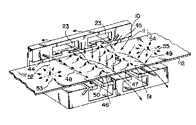
1-3. As there can be seen, the quench box 10 of the present
invention includes a longitudinal opening 11 through which the
web or endless belt extends. In the preferred embodiment of
the invention, the quench box is positioned on both sides of
an endless belt 12 with the belt passing through the
longitudinal opening 11 extending through the entire quench
box to permit the belt to be continuously advanced through the
opening 11. The upper section 13 of the quench box 10 is
equipped with a transversely extending passageway 14 through
which a quenching fluid is introduced. The quenching fluid
introduced to the passageway 14 thus impinges on the surface
of the belt 12 to provide a cooling effect on the surface of
the belt.
In the preferred practice of the invention, the
quenching fluid is introduced through a series of conduits 15
to a manifold 16. In fluid communication with the manifold 16
are openings 17 in the quench bo~ through which the quenching
fluid introduced through the conduit 15 must pass from the
slot 14 directly onto the surface of the belt 12.
As is perhaps best illustrated in Fig. 3, the
quenching fluid introduced through the conduits 15 into the
manifold 14 and then through the openings 17 preferably are
directed substantially perpendicular to the surface of the
belt 12 as illustrated by the arrows 18.
In the most preferred embodiment of the invention,
each of the conduits 15 supply separate manifolds illustrated
in Fig. 2 as 19, 20, 21, etc. which are separated from each
other by means of dividers or baffles 22. Thus, the first
conduit 15 supplies fluid to the manifold 19 which in turn is
separated from manifold 20 by means of another divider or
baffle 22. In that way, the quantity and/or temperature of
the quenching fluid supplied to each of the separate manifolds
~,i': : ,
~.: . , . . : : -
.. , ~
:
can be separately controlled to insure uniform cooling across
the surface of the belt.
Positioned on either æide of the quenching passage
means 14 are a pair of transversely extending return ports 23
including a slotted opening 24 immediately above the belt 12.
The slotted opening 24 is in fluid communication
with the surface of the belt, and is positioned to receive
quenching fluid after it has impinged on the surface of belt
12. As is illustrated in Fig. 1, the return ports 23 are in
fluid communication with return ducts 25 and 26 which in turn
communicate with drain pipes 27 and 28 for delivering
quenching fluid to a sump and vent pipes 29 and 30. In the
preferred practice of the invention, the vent pipes are
maintained at or below atmospheric pressure to relieve any gas
pressure build up in the quench box and further assure
containment of the quenching fluid.
Also defined by the quench box 13 is an internal
manifold 31 to which a containment fluid is supplied by means
of a conduit 32. The internal manifold 31 communicates with a
transversely extending slotted opening 33 extending across the
width of the quench box 10 and angled downwardly and inwardly
toward the point where the quenching fluid impinges on the
surface of the belt 12. Thus, a containment fluid introduced
through the conduit 32 into the manifold 31 passes through a
passage to the slotted opening 33 to establish a continuous
containment fluid curtain stream toward the surface of the
belt 12. That containment stream thus diverts any of the
quenching fluid flowing longitudinally in the direction of the
slotted opening 33 to the return ports 23 for passage to
return duct~ 25 and 26 and vent pipes 29 and 30.
The opposite end of the quench box 10 includes a
corresponding conduit 34 which supplies a manifold not
illustrated in the drawings which in turn supplies a
containment fluid to a transversely extending slotted opening
35. The latter slotted opening is positioned in the opposite
direction from the slotted openin~ 33 and likewise establishes
a continuous containment fluid curtain stream toward the
--8--
. ~ ~ .. ~ . . . . .
: - . . ..
: , , :
~ . . . , ~
f'~
surface of the belt. Thus, slotted openings 33 and 35, since
each is positioned on either side of the passage 14 for the
quenching fluid, serve to contain the quenching fluid between
slots 33 and 35 to assure that the quenching fluid does not
escape longitudinally along the surface of the belt 12, and,
at the same time, insures that the quenching fluid is directed
to the return ports 23 for removal from the quench box without
contaminating adjacent parts of the equipment.
In the most preferred embodiment of the invention,
the quench box 10 also includes, at the outer extremes, a pair
of vertical passages extending therethrough supplied by
conduits 36 and 37.
In the preferred embodiment, a final containment
fluid is passed substantially perpendicularly toward the
surfaae of the belt 12 to insure that the quenching fluid i8
directed toward the center of quench box 10. For that
purpose, it is generally preferred that the final containment
fluid supplied to conduits 36 and 37 be a containment gas
whereby a portion of the gas flow is directed toward the
interior of the quench box 10, thus preventing any small
amount of liquld on the surface of the belt 12 from exiting
the box 10.
In the preferred practice of the invention, the
quench box 10 also includes a lower section 38 which is a
mirror image of the upper section 13 and includes a passage 39
to supply quenching fluid to the underside of the belt 12, and
preferably through adjacent manifolds permitting separate
control of the quenching fluid across the width of the belt
12. Similarly, the lower section 38 of the quench box 10
includes slotted openings 40 and 41, respectively,
corresponding to slotted openings 33 and 35. Those slotted
openings perform the same function of supplying a containment
fluid to the underside surface of the belt 12. Similarly, the
lower section 38 includes return ducts 42 and 43,
respectively, which are in fluid communication with the
underside of the belt to insure rapid and efficient removal of
_g_
''' . ~'~'" ' ' ' :' '
i, ,:', ' :
", ' ' ~ ,,
'
"'~ :"' ", ' ' ' , ' :.
the quenching and containment fluids from the underside of the
belt 12.
In the preferred embodiment of the invention, the
quench box 10 is also provided with blow-off ports 44 and 45
to receive coolant removed from the web by the final
containment gas supplied through conduits 36 and 37. A
portion of the final containment gas introduced through
conduits 36 and 37 passes along the surface of the belt 12
causing any small amount of liguid remaining on the surface of
the belt to exit through blow-off ports 44 and 45 into return
ducts 25 and 26 for removal from the quench box.
The flow patterns of the various fluids are
illustrated in Fig. 3 of the drawings. The quenching fluld
introduced through the plurality of manifolds supplied by
conduits 15 impinges in a generally perpendicular fashion on
the surface of the belt 12 as shown by the arrows deRignated
as 18 in Fig. 3. The quenching fluid, which is preferably a
liquid, strikes the surface of the belt 12 and then flows in
both directions in a generally longitudinal manner on the
surface of the belt 12 as illustrated by the arrows 46 and 47
in Fig. 3. The containment fluid introduced through slotted
openings 33 and 35, illustrated by the arrows designated 48
and 49, respectively, forms a continuous curtain as a
containment stream, forcing the quenched liquid toward the
center of the quench box 10 for removal through return ports
23. Thus, the containment fluid, once it impinges on the
surface of the belt 12, flows in a direction generally
illustrated by arrows 50 and 51, forcing the quenching fluid
toward the center of the quench box 10 for removal through
return ports 23. The final containment gas, whose movement is
illustrated by arrows 52 and 53 and 54 and 55 can impinge on
the surface of the belt 12 in a substantially perpendicular
manner as illustrated in the drawings. Some of the final
containment gas serves to insure containment of the quenching
fluid and the containment fluid. If desired, the final
containment gas can be angled in a direction toward the center
of the ~uench box 10 to increase the velocity of the
--10--
~, ~
.. . . .
~ L ~ 3
containment gas in that direction and further assure that none
of the quenching fluid or the containment fluid can exit the
quench box 10 through the horizontal opening 11.
In the preferred practice of the invention, it is
generally desirable that the quenching fluid be in the form of
a liquid. For reasons of economy, water is usually preferred.
Other known quenching liquids can be used at greater expense.
Similarly, the containment fluid is likewise preferably a
liquid. In accordance with the most preferred embodiment of
the invention, the containment fluid is water as well. As the
final containment gas, it is generally preferred to employ air
for reasons of economy.
The quench box apparatus of the present invention is
preferably employed in the cooling of endless belts or webs
used in strip casting of metals. Its use in the strip casting
of metals, and preferably aluminum, is illustrated in Figs. 4
and 5 of the drawings.
As there shown, the apparatus includes a pair of
endless belts 56 and 57 carried by a pair of upper pulleys 58
and 59 and a pair of corresponding lower pulleys 60 and 61 of
Fig. 4. Each pulley is mounted for rotation about an axis 62,
63, 64, and 65, respectively of Fig. 5. The pulleys are of a
suitable heat resistant type, and either or both of the upper
pulleys 58 and 59 is driven by a suitable motor means not
illustrated in the drawing for purposes of simplicity. The
same is equally true for the lower pulleys 60 and 61. Each of
the belts 56 and 57 is an endless belt or web, and is
preferably formed of a metal which is low or non-reactive with
the metal being cast. Quite a number of suitable metal alloys
may be employed as is well known by those skilled in the art.
Good results have been achieved using steel and copper alloy
belts.
The pulleys are positioned, as illustrated in Figs.
4 and 5, one above the other with a molding gap therebetween.
In the preferred practice of the invention, the gap is
dimensioned to correspond to the desired thickness of the
metal strip being cast.
--11--
.:: :-. ~ :, -
:,:: : : : ~ ~
. . .
-
Molten metal to be cast is supplied to the molding
gap through suitable metal supply means 66 such as a tundish.
The inside of tundish 66 corresponds in width to the width of
the belts 56 and 57 and includes a metal supply delivery
casting nozzle 67 to deliver molten metal to the molding gap
between the belts 56 and 57. Such tundishes are conventional
in strip casting.
In accordance with the concepts of the invention,
the casting apparatus of the invention includes a pair of
quench boxes of the present invention 68 and 69 positioned
opposite that portion of the endless belt in contact with the
metal being cast in the molding gap between belts 56 and 57.
The quench boxes thus serve to cool the belts 56 and 57 ~ust
after they pass over pulleys 59 and 61, respectively, and
before they come lnto contact with the molten metal. In the
most preferred embodiment as illustrated in Figs. 1 and 2, the
quench boxes are positioned as shown on the return run of belt
12.
In a preferred embodiment, it is sometimes desirable
to employ scratch brush means 70 which frictionally engage the
endless belts 56 and 57, respectively, as they pass over the
pulleys 58 and 60 to clean any metal or other forms of debris
from the surface of the endless belts 56 and 57 before they
receive molten metal from the tundish 66.
Thus~ in the practice of the invention, molten metal
flows from the tundish through the casting nozzle 67 into the
casting zone defined between the belts 56 and 57 and the belts
56 and 57 are heated by means of heat transfer from the cast
strip to the metal of the belts. The cast metal strip remains
between the casting belts 56 and 57 until each of them i5
turned past the centerline of pulleys 59 and 61. During the
return loop, the quench boxes of the invention cool the belts
56 and 57, respectively, and substantially remove therefrom
the heat transferred to the belts by means of the molten metal
as it solidlfies. After the belts are cleaned by the scratch
brush means 70 while passing over pulleys 58 and 60, they
approach each other to once again define a casting zone.
-12-
,:
~ .
,,, , ' ~ ~ . : - .
,
The thickness of the strip that can be cast is, as
those skilled in the art will appreciate, related to the
thickness of the belts 56 and 57, the return temperature of
the casting belts and the exit temperature of the strip and
belts. In addition, the thickness of the strip depends also
on the metal being cast. It has been found that aluminum
strip has a thickness of 0.100 inches (0.254 cm) using steel
belts having a thickness of 0.08 inches (0.20 cm) with a
return temperature of about 300F (149C) and an exit
temperature of about 800F (427C).
The quench system of the present invention has been
employed to cool a continuous web fabricated of steel having a
width of 7 inches (17.78 cm) and a thickness of 0.062 inches
(0.16cm). The web was operated at a linear speed of 196 feet
per minute (59.7 m/minute) and was cooled using a coolant
water supply of 25 psi (1.7 atm.) and air as the containment
gas under a pressure of 70 psi (4.76 atm.). It was found that
complete containment of the water coolant was achieved in all
tests.
In carrying out the tests, use was made of water
flow rates through the slotted openings 33, 35, 40 and 41
(referred to as end slots) and 5 top and 5 bottom manifolds
equally distributed across the width of the web (referred to
as center slot zones). The total flow through all four, full
width, end slots and the total flow through both top and
bottom center slots in each cooling zone along with initial
and final belt temperatures by zone are set forth in the
following table where the results are given both in the
English system of units (first row for each test) and in the
metric system of units (second row for each test).
b~ "
"'.~", ." ~"" ''." '.''~ ' ',' ' ' ' '
~ " '
TABLE
,
. = WI~TI~R FLOW GPM (LlTEl~S/SEC.) INlTIAL BELT TEMP. F- (-C) FINAL BELT T~MP. F-(-C)
TEST ENI) CENTI~R SLOIS ZONES ZONXS
NO . SLOT S
1 2 3 4 5 1 2 3 ~ 51 2 3 45
1 B.6 0.0 0.0 0.tl 0.00.0532 554 576 541 506 465 484 502 520 466
0.54 0.0 0.0 0.0 0.0 0.0278290302 283 263 241 251 261 271 241
2 8.5 2.0 1.8 1.9 1.9 1.9509543577 543 508 261 341 421 410 290
0. 53 0. 13 0. 11 0. 12 0. 120. 12265 284 303 284 264 127 171 216 210 143
3 8.3 2.0 2.9 1.4 2.4 1.7624665706 668 630 415 487 559 586 521
0.52 0.13 0.18 0.09 0.150.10329352 375 353 332 213 253 293 308 272
4 13.3 1.2 3.9 3.9 4.0 1.1554583611 590 569 428 342 256 258 496
0.52 0.09 0.25 0.25 0.250.07290306 322 310 298 220 172 124 126 258
7.9 2.1 4.0 4.1 4.1 2.0638664689 670 651 473 386 299 365 490
0 . 50 0. 13 0. 25 0. 260. 260. 13 337 351 365 354 344 245 197 148 185 254
6 9.6 1.7 3.8 3.9 3.9 1.9454464473 455 436 200 207 213 214 211
0. 60 0. 09 0. 24 0. 25 0. 250. 12234 240 245 235 224 93 97 101 101 99
7 8.3 2.8 4.0 3.6 3.5 3.5634673711 6a6 660 399 410 421 479 335
0.52 0.18 0.25 0.23 0.220.22334356 377 363 349 204 210 216 248 168
8 10.1 3.0 3.5 3.6 3.6 3.0571587602 589 575 348 317 285 295 303
0.64 0.19 0.22 0.23 0.230.19299308 317 310 302 176 158 141 146 151
9 14.3 4.4 3.8 4.5 4.5 4.5614643671 641 611 207 255 302 246 229
0.90 0.28 0.24 0.28 0.280.28323340 355 339 322 97 124 150 119 109
One of the advantages of the method and apparatus of
the present invention is that there is no need to employ a
thermal barrier coating on the belts to reduce heat flow and
thermal stress, as is typically employed in the prior art. The
absence of fluid cooling on the back side of the belt while the
belt is in contact with hot metal in the molding zone
significantly reduces thermal gradients and eliminates problems
of film boiling occurring when the critical heat flux is
exceeded. The method and apparatus of the present invention also
minimizes cold framing, a condition where cold belt sections
exist in three locations, namely (1) before metal entry and (2)
-14-
: . ' ~ ' ~, .: : , ' ,
~ L ~ LJ~ 3
on each of the two sides of mold zone of the belt. Those condi-
tions can cause severe belt distortion.
In accordance with another embodiment o~ the present
invention, it is also possible to employ the concepts of the
present invention in a method and apparatus utilizing a single
belt. That embodiment is schematically illustrated in Flg. 6 of
the drawings. In that embodiment, a single belt 71 is mounted on
a pair of pulleys 72 and 73, each of which is mounted for
rotation about an axis 74 and 75, respectively. Molten metal is
supplied to the surface of the belt by means of a tundish 76.
Cast product 77 exits the top surface of belt 71. As is the case
with the embodiment illustrated in Flgs. 1 and 2, the ultimate
embodiment of Fig. 6 utilizes the quench box of the invention 78,
preferably positioned on the return of the belt. The quench box
78, like that of the quench box in Fig. 1, serves to cool the
belt when it is not in contact with the molten metal on the belt
71.
It will be understood that various changec and
modifications can be made in the details of structure
configuration and use without departing from the spirit of the
invention, especially as defined in the following claims.
-15-
: . : ~ :
', ,:
'' :
', ' ' '