Language selection

Search

Patent 2112122 Summary

Third-party information liability

Some of the information on this Web page has been provided by external sources. The Government of Canada is not responsible for the accuracy, reliability or currency of the information supplied by external sources. Users wishing to rely upon this information should consult directly with the source of the information. Content provided by external sources is not subject to official languages, privacy and accessibility requirements.

Claims and Abstract availability

Any discrepancies in the text and image of the Claims and Abstract are due to differing posting times. Text of the Claims and Abstract are posted:

  • At the time the application is open to public inspection;
  • At the time of issue of the patent (grant).
(12) Patent Application: (11) CA 2112122
(54) English Title: METHOD FOR CHANGING RAILWAY SLEEPERS AND EQUIPMENT FOR APPLYING THE METHOD
(54) French Title: METHODE DE REMPLACEMENT DE TRAVERSES DE CHEMIN DE FER ET MATERIEL UTILISE POUR CE FAIRE
Status: Deemed Abandoned and Beyond the Period of Reinstatement - Pending Response to Notice of Disregarded Communication
Bibliographic Data
(51) International Patent Classification (IPC):
  • E01B 29/10 (2006.01)
  • E01B 29/09 (2006.01)
(72) Inventors :
  • NIIRANEN, JAAKKO (Finland)
(73) Owners :
  • JAAKKO NIIRANEN
(71) Applicants :
(74) Agent: KIRBY EADES GALE BAKER
(74) Associate agent:
(45) Issued:
(86) PCT Filing Date: 1992-06-23
(87) Open to Public Inspection: 1993-01-07
Examination requested: 1999-06-23
Availability of licence: N/A
Dedicated to the Public: N/A
(25) Language of filing: English

Patent Cooperation Treaty (PCT): Yes
(86) PCT Filing Number: PCT/FI1992/000197
(87) International Publication Number: WO 1993000477
(85) National Entry: 1993-12-21

(30) Application Priority Data:
Application No. Country/Territory Date
913063 (Finland) 1991-06-24

Abstracts

English Abstract

2112122 9300477 PCTABS00019
The object of the invention is a method for changing railway
sleepers. In this method the sleepers (2) of the rails (1) are
removed and new sleepers (3) are put in place. By using a lifting
device (4) the rails (1) are lifted, at the same time they are
loosened from the sleepers, the sleepers (2) are removed from under the
rails and new sleepers (3) are brought under the rails and the
railway ground is levelled by using a plough (5) which is placed
under the rails (1) and which is pulled by the working machine (6).
In addition, the object of the invention is equipment which
permits the application of the method. At present, changing sleepers
is slow and it requires much time to move equipment on to and off
from the line. In the method, according to the invention, the
plough (5) is used as a foundation base on which the rails rest
during the work, and the plough can be left under the lifted railway
section when the work has to be interrupted so that trains can
run over it. In the equipment, according to the invention, the
working machine (7) has supporting stands (11) which support it when
it is lying on top of the rails, and during the work the working
machine and the plough have been arranged to support the railway
line.


Claims

Note: Claims are shown in the official language in which they were submitted.

WO 93/00477 PCT/FI92/00197
CLAIMS
1. A method for changing railway sleepers, in this method the
sleepers (2) lying transversely to the rails (1) are removed and
new sleepers (3) are placed under the rails, by using a lifting
device (4) the rails (1) are lifted upwards and simultaneously the
rails are unfastened from the sleepers, the sleepers (2) are moved
away from under the rails and new sleepers (3) are brought under
the rails after which the rails are laid down and the sleepers are
fastened to the rails, the railway ground is levelled by using a
plough (5) which is placed below the rails (1) and which is pulled
by a working machine (6) below the rails (1), c h a r a c t e r i z -
e d in that the plough (5) is used as a foundation base on which
the rails rest during the work and that the plough is left under the
lifted railway section when the work is interrupted so that trains
can run on top of it.
2. A method according to claim 1, c h a r a c t e r i z e d in that
the new sleepers (3) are placed under the rails (1) by using a
working machine (7) equipped with supporting stands (11), this
working machine rests on the supporting stands on top of the
railway line and this working machine is used for holding the
rails up.
3. A method according to claim 2, c h a r a c t e r i z e d in that
the working machine (7) has been placed behind the plough (5)
and/or partly on top of it and that the plough is pulled between
the working machine (7) and the lifting device (4) by using a
pulling device (9) fastened to the working machine (6) which lies
at some distance from the other working machines.
4. A method according to one of the claims 1-3, c h a r a c t e r -
i z e d in that the rails (1) are gripped by the arresters (15) of
the lifting device (4) and the arresters are moved upwards by
using a power device (14) when the lifting device is against the
sleepers (2) so that the rails are loosened from the sleepers.

WO 93/00477 PCT/FI92/00197
5. Equipment for changing railway sleepers, this equipment
consists of a lifting device (4) to be placed on top of the rails (1)
for lifting the rails (1) upwards and loosening them from the
sleepers (2) lying transversely under the rails, a working machine
(7) for placing new sleepers under the rails, a plough (5) to be
moved under the rails (1 ) for levelling the ground under the
railway line, c h a r a c t e r i z e d in that the working machine
(7) has supporting stands (11) which support it when it lies on top
of the rails, and that the working machine and the plough have
been arranged to support the railway line during work.
6. Equipment according to claim 5, c h a r a c t e r i z e d in that
the working machine (7) has been placed behind the plough (5)
and/or partly on top of it.
7. Equipment according to claim 5 or claim 6, this equipment
consists of a working machine (6) for pulling the plough by using a
pulling device (9), c h a r a c t e r i z e d in that the working
machine (6) has been placed at a distance from the lifting device
(4) and connected to it with a boom (10).
8. Equipment according to claim 7, c h a r a c t e r i z e d in that
the pulling device (9) of the plough (5) has been placed under the
lifting device (4) below the rails by means of a boom (10).
9. Equipment according to one of the claims 5-8, c h a r a c t e r -
i z e d in that the lifting device (4) has arresters (15) fastened
reversibly to the sides of the device and a power device (14) for
moving the arresters vertically.

Description

Note: Descriptions are shown in the official language in which they were submitted.


wv s3/00477 2 !~ ~ 2 1 2 r~ PCl'/F192/00197
METHOD FOR CHANGING P~AILWAY SLEEPERS AND EQUIPMENT FOR
APPLYING THE MET~OD
Th~ obj~ct of the invention is a method for chan~ing r~ilway
5 sleepers, in this method tha sleepers Iyin~ trans~ersely under the
rails are removed and new sl~0pers are placed under ths rails. The
rails are lifted upwards with ths help of a liftin~ device and at
the same ~ime they are unfastelled from th~ sleep~rs, the sleepers
are remov~d from under the rails and new sieepers are put down
10 under th~ rails. Then th~ rails are relaid, the new sleepers a;e
fastened to the rails, the ground underneath is levelled by a
plou0h which is position~d under th~ rails and pulled there by
means of a working machine. In addition, th~ object of th~
invention is the equipment which allows the application of the
15 abov~ thod.
Sle~pers Iyin~ under the rails are usually made of wood or
concrete. Wooden sleepers have to be replaced at ra~ular
intervals. To remove the sleep~rs, the :rails first have to b~
2 0 unfastened from the sleQpers and after that, the sleepers are
puiled ~ut from und~r the rails. The new sleepers are forcibly
pushed under the rails eith0r by usin~ a machine for changing
sleepers o r by USiR 9 a device ~for chan~in~ ;sleepers which is
. mount~d, for example, on an ~xcavat~r, and the n~w sleepers are
25 ~ fastened to the ~railsO Sl~pers ~mad~ of concrete hav~ to be
changed when basie repairs need to be done to the railway line or
wh~n track gauge~ is changed. When such: large pieCRS of equipmènt
ar3 bein~ used j the entire section of th~ railway network has to
be closed to traf~ic, which is awkward. The presentwday
3 0 equipment is large-si2ed, compJex and cumbersomff. Also, even
when working with small scale equipment and when devices are
b~in~ moved ~nto a line or away from it, trains cannot run on the
line and thus the equipment must ba remov~d to let the trains
run. This tak~s a lot of time moYing the machines away from the
35 lines and putting thenl back on a~ain.

2 ~
WO 93/00477 PC~/F192/OOlg7
The aim of the invention is to bring forward a method for chan~ing
railway sle~p~rs, such that, by the use of this method,
disadvantages connected with present methods can be avoided. In
particular, the aim of the inventiorl is to brin~ forward a method,
5 such that, by the use of this me~hod, moving deyic~s on to th~
line and off the line and chan~in~ sleepers oan bs done more
quickly and n~eds less manpowsr than before. E~esides, the aim of
tha invention is to brin~ forward such equipm0nt which will allow
for application of the method. This equipment is easy to use,
10 efficient, can be ~ot ready rapidly and can be quickly removed
from the line.
The airn o~ th~ inv~ntion is achieved with the method and
equipment characterizsd in the foliowing claims.
1 5
In the method aocordin~ to this inv~ntion, a plou~h is us~d a~ a
foundation bas~ on which rails rest durin~ ~h~ work, and thi
plough oan be l~ft under the railway section under repair when
work has to be in~rrupted so that trains can run over it. In this
20 way, th~ plough does not need to be removed from under the rails
until the work is compl~ted and it does not n~ed to be piaced
under the rails each time work is star~ed. This speeds up work
considerably as the actual work can be started much faster than
befora. 13uring work, the ~ro~nd under the line is levelled by usin~
25 a plou~h which is pulled by ~means of a workin~ mæhlne below the
rails when :th~ rails are lifted up. Wh~n the ~round has been
Ievelled, new sleepors can be placed on an even foun~ation. In this
way, th~ sleepers~ are aiways evenly against th~ foundation even
if spaces batween the sleepars have bean changed.
i -
In a favourabls cmbodim~nt of the: invention, new sleepcrs are
placed under rails with th~ h~lp of a workin~ machine equippéd
with supporting stands. Ths workin~ machine lies over th~
railway line and it :simultaneously holds the rails up. P~ails can be
3 5 simply and ssclJrely Iifted up and slespers can easily b~ put in
their place by using the same working machine. This working
machine lies at a distance from a liftin~ device so that a chosen

Wo 93/nO477 21 1 2 .~ 2 ~ PCr/F192~00197
length of ~he line can be lif~d. Ths workin~ machine is favourably
situated behind th~ plou~h and/or partly on top of it. The plou~h is
being pulled between the liftin~ device and the workin~ machine
with the help of a pulling device fastened to another workin~
machine. Th~ other working machine is situate~ at some distanGe
from the other devic~s.
In th~ following, the invention will be explain~d in more detail by
referring to th~ attached drawing in which
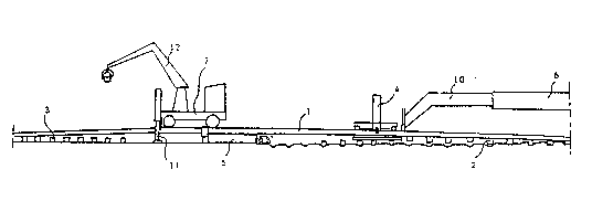
10 fig. 1 shows a side view of the equipment for applying the method
accordin~ to the invention
fig. 2 shows a top view of the ~quipment according to fig. 1, and
fi~. 3 shows a back view of an embodirnent of a liftin~ device of
the equipment according to the invention.
1 5
In the embodiment shown in fig~lre~ 1 and 2, the equipment
consists of a liftin~ device 4, plough 5 and workin~ machines 6
and 7. The lifting device 4 has been connected to a boom 10 of the
workin~ rnachine 6. The lifting device has been placed above raiis
20 1 so tha~ it will be on top of sleepers 2.. The workin~ machine 6
has been placed above the rails at such a distanc~ from the liftin0
device that it does not prsss the rails at the position of the
lifting deYiceO The workin~ machine 7, which in this embodiment
is a railway ri~, has been placed on top of the rails at a distance
25 behind the lifting d~vice. The workin~ machine is fastened to tha
rails and it has: supporting stands 11, with th~ help of which it
can lift the rails to the desired hei~tlt. Besidesl a derrick 12 has
b~n placed on the working machine to slide new sleepers 3 under
ths rai5s.
3 0
A plou~h 5 has b~en placed under the raiis so that the w~rkin~
machine 7 is behind it and partly on top of it. The plough has be~n
cennected to th~ workin~ machine 6 farth~st to the front by usin~
a chain or cable which acts as a pulling devic~ 9~ The chain has
35 been tak~n under the liftin~ device to the boom and from there to
the working machinc. The plough has besn fastened movably to the
rails in a previously known way and in the back part it has

21~.212.~
WO !~3/00477 PC~/F192/00197"~
supports for keapin~ th~ rails at th~ right hei~ht and the plou~h
straight. The plough has been made of strong materials and when
work has to be interrupted it can bs left under the lifted railway
section where it acts as a found~ticn base and it need not be
removed from ulldar the line at the end of ea¢.i:l working stage.
When a new shi~ of work begins, the plou0h is immediately ready
~or work.
The lifting device shown in figurs 3 eonsists of a frame 13 and to
the fram~, cylinders 14 have b~n fastened and to the sides of the
frame arrest~rs 15 have been reversibly fastened and they have
been fitted with grippin~ points.
Wh~n railway sieepers are chan~ed usin~ the method accordin~ to
the invention, a lifting device 4 is placed on the selected spot of
the line. The lower part of the lifting device is plac~d a~ainst
sleep~rs 2 and the arresters of the~ liftin~ device are turned to a
position shown in fi~ure 3 so that their: ~rippin~ points~:are
against rails 1. By usin~ hydra~llic cylinders 14, the a~resters and
~he: rails fastened to ~hem are lifted upwards. The lower part: of
the lifting device is a~ainst railway sleepers so: that spikes and
foundation plat~s~are loosen~d~ along ~with~the rails when they ar~
pulied: upwards and ~the~:rails are ~quickly; loos:ened from the
sleepars. After this, :the old railway sieeper is pulled ;aside. The
lif~ing device is moved ~orward~:and the work~ is repeated.
:~
The working maclline 7 or the railway ri8 7 has b~en placed on top~
of the rails at a distance fronn the lifting~ device and with the help
of i~s supportin~ stands the raiis are also held up. By using the
`~ 30 derrick p!ac~d on the rig, new railway sleepers 3 are movsd under
the rails where fastenin~ of the ~ sleepers takes place, for
instance, manualiy. Th3re are no sleepers at this point ~f the
railway: section so: that~ sleepsrs can be slid unhindered under th~
rails ~rorn the sid~.
3 5
The ~plough 5 has :been placed in front of the railway ri~ and partly
under i~. The uneven ground und~r the lina is levelled and lowered

WC) 93/00477 2 ~ PCI'/F192/00197
by using the piou~h which is pulled by usin~ the pullin~ device 9
fastened to the workin~ machine 6. The plou~h vibrates at a hi~h-
frequency which is an advanta~e to overcome friction. When the
plough has been pulled to the lif~ing device th~ workin~ machine 6
5 and the liftin~ deYic~ are moved fonNard and the operations are
repeatad. Also the railway rig is moved forward as th~ work
pro~resses. As ~he plou~h moves forward, banks will form on th~
edges of the moldboards, and the sleepers ar~ placed between
these banks under th~ railway line.
1 0
The equipment accordiny to the invention has the great advarlta~e
that the devices it consists of are separate, relatively small-
sized and it is easy to lift them off the line or back on to the line
as time demands. They need not be transferred to a sideline or
15 taken to the naarest station wh~n the work is not in pro~ress.
The invention will not be limited to the described favourable
embodiment but it may vary within the frarne of the innovative
idea formed by ths claims.

Representative Drawing
A single figure which represents the drawing illustrating the invention.
Administrative Status

2024-08-01:As part of the Next Generation Patents (NGP) transition, the Canadian Patents Database (CPD) now contains a more detailed Event History, which replicates the Event Log of our new back-office solution.

Please note that "Inactive:" events refers to events no longer in use in our new back-office solution.

For a clearer understanding of the status of the application/patent presented on this page, the site Disclaimer , as well as the definitions for Patent , Event History , Maintenance Fee  and Payment History  should be consulted.

Event History

Description Date
Inactive: IPC from MCD 2006-03-11
Application Not Reinstated by Deadline 2002-06-25
Time Limit for Reversal Expired 2002-06-25
Deemed Abandoned - Failure to Respond to Maintenance Fee Notice 2001-06-26
Letter Sent 1999-09-07
Inactive: Application prosecuted on TS as of Log entry date 1999-09-07
Inactive: Status info is complete as of Log entry date 1999-09-07
Request for Examination Requirements Determined Compliant 1999-06-23
All Requirements for Examination Determined Compliant 1999-06-23
Application Published (Open to Public Inspection) 1993-01-07

Abandonment History

Abandonment Date Reason Reinstatement Date
2001-06-26

Maintenance Fee

The last payment was received on 2000-06-07

Note : If the full payment has not been received on or before the date indicated, a further fee may be required which may be one of the following

  • the reinstatement fee;
  • the late payment fee; or
  • additional fee to reverse deemed expiry.

Please refer to the CIPO Patent Fees web page to see all current fee amounts.

Fee History

Fee Type Anniversary Year Due Date Paid Date
MF (application, 5th anniv.) - small 05 1997-06-23 1997-06-09
MF (application, 6th anniv.) - small 06 1998-06-23 1998-06-15
MF (application, 7th anniv.) - small 07 1999-06-23 1999-05-27
Request for examination - small 1999-06-23
MF (application, 8th anniv.) - small 08 2000-06-23 2000-06-07
Owners on Record

Note: Records showing the ownership history in alphabetical order.

Current Owners on Record
JAAKKO NIIRANEN
Past Owners on Record
None
Past Owners that do not appear in the "Owners on Record" listing will appear in other documentation within the application.
Documents

To view selected files, please enter reCAPTCHA code :


To view images, click a link in the Document Description column. To download the documents, select one or more checkboxes in the first column and then click the "Download Selected in PDF format (Zip Archive)" or the "Download Selected as Single PDF" button.

List of published and non-published patent-specific documents on the CPD .

If you have any difficulty accessing content, you can call the Client Service Centre at 1-866-997-1936 or send them an e-mail at CIPO Client Service Centre.


Document
Description 
Date
(yyyy-mm-dd) 
Number of pages   Size of Image (KB) 
Abstract 1995-08-19 1 70
Description 1995-08-19 5 343
Claims 1995-08-19 2 123
Cover Page 1995-08-19 1 33
Drawings 1995-08-19 1 42
Claims 1999-06-23 4 119
Representative drawing 1998-12-16 1 11
Reminder - Request for Examination 1999-02-24 1 117
Acknowledgement of Request for Examination 1999-09-07 1 193
Courtesy - Abandonment Letter (Maintenance Fee) 2001-07-24 1 182
PCT 1993-12-21 8 275
Fees 1996-06-06 1 63
Fees 1995-06-20 1 52
Fees 1994-05-26 2 82