Note: Descriptions are shown in the official language in which they were submitted.
!W~ 93!11949 ~ ~ ~~ ~ ~ g P~'f/~S92/10~42
v~
1
PLURAL-SHEET HOLDER
The present invention relates to a holder for
holding a plurality of sheets. The invention is
particularly useful as a holder for holding computer
S printout sheets, and is therefore described below with
respect to this application.
Computer printout sheets represent a widely used
means for presenting all kinds of data. As increasing
amounts of such data accumulate and storage space becomes
more expensive, there is an increasing need for filing
systems employing holders that are capable of providing
efficient paper storage while taking up a minimum of space.
A number of sheet-holder systems have been
described, for example, in US Patents 1,004,7??, 1,644,541,
and x;775,257, and in British Patent No.802,577, which
employ flexible cords for securing the stack of sheets
withan the holder. However, none of the devices described
can efficiently and compactly hold various numbers of
sheets having different ~.rrangements of perforations, and
peranit the ~h~et holding capacity to tae increased or
decreased as may be required.
According to the present invention, there is
provided a holder for holding a plurality of sheets formed
with holes adj~a.cerit at least one of their edges, comprisinge
2~ a backing member; and GOrd means having at one end two
~.engths of cords receivable through tl~e holes of a plurality
~f sheets and terminating in a pair of mating connectors
connectible together to permit the plurality of sheets to be
s'ecur~d together by th,e cord means; the two lengths of cards
in the cord means being carried by a common movable member
movable along one axis of the backing member for locating
the two lengths of cords along the axis with respect to the
holes of the sheets to be secured together.
According to further features in the'preferred
embodiments of the invention described below, the common
movable member is slidable along a track extending at the
WHO 93/11949 ~CC/1J~92/108~42
r
2
upper end of the backing member along its width. Also, the
end of the cord means opposite to that of the two lengths of
cord terminating ~.n the pair of mating connectors is secured
to a length-varying device enabling the effective lengths of
the cord means to be varied according to the number of
sraeets to be secured by the cords.
The mentioned cord means may be constituted of one
card whose opposite ends terminate in the mating connectors;
alternatively, the cord means may include a pair of chords
having one of their ends terminating in the mating
connectors.
Several embodiments of the invention are described
below for purposes of example. In one described embodiment,
the length-varying device comprises two fabric strips of a
hook-and-loop fastener, e.g., a "Velcro°° (Reg. T.M.)
fastener. One fabric strip of the hook-and-loop fastener is
secured to the opposite end of the cord means, and the other
fabric strip of the fastener is fixed to and extending along
the respective axis (e.g., width) of the backing member. In
a second described embodiment, the length-varying device
comprises a xeel secured to and slidable with the slide.
Tn all the described preferred embodiments, there
are two of the cord means carried by two slides movably
mounted to the opposite sides of the backing member.
2S Holders constructed in accordance with the
foregoing features enable the user to freely adjust the cord
spacings and cord lengths as desired; and thereby to store
all k~.nds of sheets securely, to retrieve any specific sheet
efficiently, and to minimize the storage space required for
30 each holder. These features make the novel holders
particularly useful for storing computer printouts, but of
course the novel holders could also be advantageously used
in holding or storing other types of sheets. Tn addition,
such holders permit unburst computer printouts held in the
35 holder to be opened 180° and to be completely read and used,
thereby saving paper and space.
CA 02112134 2003-07-15
3
According to a still further broad aspect of the
present invention there is provided a holder for holding
a plurality of sheets formed with alignable holes. The
holder comprises a backing member and cord means
terminating in a pair of mating connectors connectable
together after having passed through the holes of the
sheets to secure the sheets together. The cord means has
an opposite end secured to a length-varying device
enabling the length of the cord means to be varied
according to the number of sheets to be secured by the
cord means.
The preferred embodiment of the present invention
will now be described with reference to the accompanying
drawings in which:
Fig. 1 illustrates one form of holder constructed in
accordance with the present invention;
Fig. la is a sectional view along line a-a of Fig.
l; and
Figs. 2 and 3 illustrate two other forms of holders
constructed in accordance with the present invention.
The holder illustrated in Figs. 1 and 1a is intended
for holding a plurality of sheets (not shown) formed with
holes or perforations adjacent their opposite edges in
order to secure a plurality of sheets together.
Normally, the plurality of sheets to be held by each
holder would be the same width or length and would have
the holes at the same location on the sheet, although the
location of the holes on the sheets may be different for
different holders. An important feature of the holder
illustrated in Fig. 1 is that it can easily accommodate
any number of sheets, and substantially any location of
the holes thereon, assuming the hole location is the same
for all the sheets of the respective holder.
CA 02112134 2003-07-15
3a
The holder illustrated in Figs. 1 and la comprises a
backing member 2 having a track 4 secured to and
extending along the upper edge of the backing member for
its complete width. A pair of slides 6 and 8 are
slidably mounted at the opposite ends of track 4 so as to
be selectively positionable at any desired location along
the width of the backing member.
Each slide 6, 8, carries a pair of cords 10, 12
including mating connectors at one of their ends. For
example, the cord pair 10 includes a conical pin 10a at
the end of one cord, and a conical socket 10b at the
corresponding end of the other cord of the pair. These
mating connectors may be quickly attached to and detached
from each other to enable the cords to be passed through
the holes of individual sheets and then to be attached
together in order to secure the plurality of sheets to
the holder.
'iV~ 93/11949 P4:T/IJS9Z/10~42
4
It will be appreciated that each pair of cords 10,
12, could include two separate cords having the mating
connectors at one of their ends, or a single cord folded at
an intermediate portion and carrying the mating connectors '
S at its opposite ends.
Track 4 is lined fox its complete length with a
long strip 19, constituting one element of a ~aook-and-loop
fastener, such as a "Velcro" (Reg. T.M.) fastener. The ends
of the two pairs of cords 10, 12 opposite to their mating
connectors (10a, 10b and 12a, 12b) are secured to short
strips 16, 18 of the other "Velcro" fastener element
cooperable with strip 14. Fox' example, the long strip 14
includes the loops of the "Velcro" fastener, whereas each of
the short strips 16, 18, includes the hooks of that
IS fastener .
. The backing member 2 may be made of stiff
cardboard, plastic, metal or the like. The track 4 is
preferably made of plastic or metal. As shown in Fig. 1a,
its opposite edges are of U-configuration. Thus, the inner
edge 4a of U-configuration is adapted to be secured to the
upper edge of the backing member 2; whereas the outer edge
4b, also of U-configuration, is adapted to receive the bead
2~? of a cover sheet 22 to be applied over the backing member
an8 the stack of sheets held thereby, or to receive part of
a drawer: The U-configuration edge 4b of track ~4 may also be
used for suspending the holder and its sheets fr~m a
supporting member; such ~s a supporting rail in a file
Cabinet.
The holder illustrated in Figs. 1 and 1a may be
3~ used in the following manner:
First, the two slides 6, 8, are preset along the
track 4 to the proper position so as to locate the
respective pairs l0, 12 of cords in alignment with the holes
of the sheets to be secured by the holder. When but a few
D
sheets are to be secured by the holder, the two "Velcro"
strips 16, 18, would be located closer to the center of
track 4, thereby providing relatively short lengths of the
W(> 9~/1 ~ 9~9 ~~ ,P ~~ ,,.~,~ PLT/9JS92/ 1042
~~~.~.r.~~J~
cords exiting from the tracks and receivable through the
holes in the paper sheets. The paper sheets are secured
together by attaching the mating connectors ~10a, 10b and
12a, 12b) of each pair of cords to each other after the
S cords have been passed through the holes in the sheets.
Whenever another sheet is to be attached, or..a
sheet is to be removed, this can be easily dole by merely
opening the mating connectors and adding or removing the
sheet.
If a larger number of sheets are to be held by the
holder, the two "Velcro" strips 16, 18, may be moved
outwardly along track ~, thereby to increase the length of
the cords 10, 12, available for securing the sheets
together; and if the number of sheets to be secured is
decreased, the "Velcro" strips 16, 18 may be moved inwardly
to reduce the lengths of the cords 10, 12 available for
securing the sheets together.
Tt wild thus be seen that the holder illustrated
in~Figs. 1 and la efficiently adapts itself to the types o~
2A sheets to be held tpart~.cularly to the location o~ the holes
through the sheets), and also ef~icient.ly adapts itself to
the number of sheets o be held.
The holder illustrated in Fig. 2 is o~ very
similar construction as that illustrated in Figs. 1 and 1a,
arid th~refbre the same reference numerals have been used to
xd~nta~y tyke corresponding elements in order to ~acilitate
understanding its construction and manner of use. urn
importaa~t difference, however, is that the holder
illustrated in Fig. 2 includes a locking member, therein
designated 30 and 32, respectively, for each~af the two
pains of cords l0, 12, far locking the cords at a
preselected length.
Thus, locking member 30 is slidably disposed
b~t~aeen slide 6 and Velcro strip 16 and cooperates with
cards l0 to lock those cords at any desired length; whereas
Locking member 32 is slidably disposed between slide 8 and
Velcro strip 18 and is cooperable with cords 12 for locking
WO 93/119x9 P~'/'~592/10842
.> ~ c,~ ~ "'',
f~r .A. ~~_ f-d
6
those cords at a preselected length. For example, the two
locking members 30, 32, may have inclined underlying
surfaces which serve as wedges to lock their respective
cords when the locking members are in one position (e. g.,
S adjacent to their respective slides 6, 8 as shown in Fig.
2), and to release the cords when in another position (e. g.,
adjacent to their respective Velcro strips 1 ~,~ 1~8 ) .
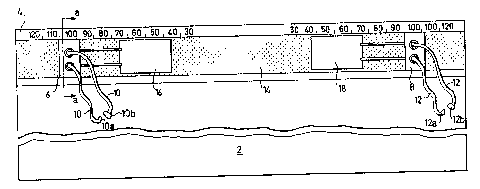
Fig. 3 illustrates a further holder constructed
similar to that of Fig. 2, except that the length--varying
device provided for each pair of cords is in the form of a
reel, rather than of a Velcro fastener.
Thus, the holder illustrated in Fig. 3 includes a
backing member 102, a track 104 secured to and extending
along its upper edge for'its complete width, and two slides
35 106 and 108 slidable along the track and each carrying a
pair of cords 110, 112 having mating connectors 110x, 110b,
and 112x, 112b permitting a plurality of sheets to be
secured together. In the holder of Fig. 3, the opposite
ends of the cords are secured to a reel 116, 118,
respectively, which may be rotated in order to increase or
decrease the lengths of the respective pair of cords 110,
112, according to the number of sheets to be secured by the
holder.
The holder of Fig. 3 further includes a pair of
2S locking~anembers 13'0, 132, slidable on track 104 for locking
the respective pair of cords at a preseiecte~ length. Thus,
if the two locking members 130, 132 are slid to the
positions illustrated in Fig. 3, adjacent to their
respective slides 106, 108, they lock their respective cords
3p 110, 112 (a. g., by a wedging~surface as described above
wedging the cords between the locking member and the track);
whereas when the two locking members are moved to be
adjadeht to their respective reels 116, 118, they free the
cords for changing their effective lengths in order to
35 increase or decrease the number of sheets to be secured by
the cords. The track 104 may include markings, as shown at
134 and 136, to indicate the locked or unlocked positions of-
CA 02112134 2003-07-15
7
the locking members; and the reels 116, 118, may be
spring-biased in the winding direction, so as to
facilitate the extension or retraction of the cords when
released by their respective locking members. The reels
116, 118 are slideable along the track 104.
The track 104 may include further markings, as shown
at 138, to indicate the positions of the slides 106, 108,
and thereby of their respective cords 110, 112, from the
edges of the track, so as to accommodate sheets having
holes at specified locations with respect to the opposite
edges of the sheets.
While the invention has been described with respect
to several preferred embodiments, it will be appreciated
that many other variations and modifications may be made.
For example, the holder could include only one pair of
cords, each cord carrying one of the mating connectors
and mounted on a separate movable member, e.g., a track
or a Velcro strip movable along the edge of the backing
member. Another variation would be to include more than
two pairs of cords, e.g., three or four pairs, movable
along the edge of the backing member. Many other
variations will be apparent.