Note: Descriptions are shown in the official language in which they were submitted.
1 6 9
APPARATU8 AND NETHOD FOR TESTING TUBULAR PRODUCTS
Field of the Invention
This invention relates to the testing of
tubular products and more particularly to the testing
of such products to determine the compressive strength
thereof.
Background of the Invention
Cylindrical cores and tubular containers are
very widely used for various and sundry purposes. In
use, the cylindrical cores and many of the tubular
containers (hereinafter referred to as "tubular
products" or just "tubes") are subjected to compressive
hoop stress due to radial compression or pressure on
their outside curved surface. A tubular product's
ability to withstand such service conditions and
thereby perform its purpose and satisfy end-users'
needs without operational difficulties necessitates
that it possess sufficient compressive strength.
Manufacturers of such tubular products must have
quality assurance capabilities to ensure that their
tubular products have the requisite compressive
strength characteristics.
One of the principal requirements of an
effective quality assurance program is a quality-
control test to measure reliably the compressive
material strength of production tubular products.
While several different methods of testing tubular
products are currently in use, such currently available
2112~
testing methods do not address the needs of either the
manufacturer or the consumer. For example, a diametral
compression flat crush test method is currently in use.
While such a test can be useful for comparative
purposes, it neither measures the material's
compressive strength, nor represents service
conditions.
Other testing methods for such tubular
products have been proposed, but none has been found to
be suitable since all have deficiencies and
disadvantages. One such testing method utilizes a belt
wrapped around the tubular product and then pulled in
tension to load the tube in radial compression. This
belt testing method has serious deficiencies and
disadvantages which include the fact that the load on
the tube varies with the angle at which the belt is
pulled. Another of these test methods involves direct
loading of the tube by hydraulic fluid. Beyond the
problems of direct contact of the hydraulic fluid with
the tubular product being tested, difficulties in
obtaining a reliable hydraulic seal and the general
uncleanliness and operator inconvenience caused by an
open hydraulic fluid system, direct hydraulic loading
of tubular products initiates buckling rather than a
compressive material failure.
Still another of these previously proposed
testing methods utilized the radial loading in
compression of tubular products by small balls
surrounding the tubular product. The balls were loaded
longitudinally by an axial testing machine through a
mechanical plunger. However, this ball testing method
did not provide uniform loading along the length of the
curved surface of the tube. The results of this
testing method were therefore unsuitable either for
quality control or for research.
It is therefore an object of the present
invention to provide an apparatus and method for
211~1~J
--3--
testing the compressive strength of tubular products
which overcomes the deficiencies and disadvantages of
currently used and previously proposed testing methods
and apparatuses.
Summary of the Invention
The foregoing object of the invention is
accomplished by an apparatus and method which are: (a)
sufficiently reliable for both laboratory use and
quality control testing in a production environment;
(b) sufficiently simple and affordable to be located in
the production area of a typical factory making tubular
products; and (c) operable by persons having only those
skills normally possessed by quality assurance
personnel typically involved in the manufacture of
tubular products. Additionally, the apparatus and
method of the present invention provide: (a) uniform
radial, compressive loading over the entire outside
curved surface of the tube (both along the length and
around the circumference) thereof; (b) loading in
compression of the tube in such a manner that failure
thereof is material in nature (compressive strength)
rather than structural in nature (e.g. buckling); (c)
for immediate detection and signaling of the onset of
tube failure; and (d) for continuous monitoring of the
magnitude of the pressure being applied to the outside
curved surface of the tube.
The apparatus of the present invention
includes a housing having an enclosed cylindrical
cavity therein, tubular bladder means in the cavity
defining a pressure chamber larger than the tube to be
tested and a fluid receiving space between the bladder
means and the inside wall of the housing, sufficient
small balls to fill the pressure chamber around the
tube being tested, and means for pumping hydraulic
fluid into the fluid receiving space between the
bladder means and the housing. The purpose of this
fluid is to uniformly pressurize the balls and thereby
2 ~ 6 9
--4--
apply uniform pressure over the entire external curved
surface of the tube being tested. Pressure monitoring
means is provided for continuously monitoring the
pressure being applied and for immediately detecting
the onset of failure of the tube.
Brief Description of the Drawings
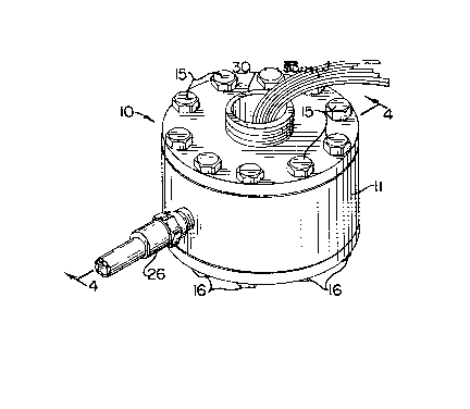
Figure 1 is a perspective view of the
apparatus of the present invention;
Figure 2 is an exploded perspective view of
the apparatus shown in Figure l;
Figure 3 is a view similar to Figure 1 with
the top end cap removed to illustrate a tubular product
in position to be tested;
Figure 4 is a sectional view taken
substantially along line 4-4 in Figure l;
Figure 5 is a sectional view similar to
Figure 4 illustrating hydraulic fluid being pumped into
the space between the bladder means and the housing to
apply pressure to a tube being tested; and
Figure 6 is a view similar to Figures 4 and 5
illustrating the removal of a tube after testing and
the removal of the small balls from the pressure
chamber.
Description of the Preferred Embodiment
Referring more specifically to the drawings,
there is illustrated therein an apparatus generally
indicated at 10 incorporating the features of the
present invention. Apparatus 10 comprises a housing 11
having a cylindrical cavity 12 therein. Cavity 12
preferably has the upper and lower end portions 12a and
12b thereof beveled outwardly.
A top end cap 13 is mounted on the top of
housing 11 and has a frusto-conical portion 13a
projecting into and closing the upper end of cavity 12.
The bevel of the upper end 12a and the slope of conical
portion 13a are preferably substantially the same for a
close fit.
-5- 2 1 1 ~ 3
A bottom end cap 14 is mounted on the lower
end of housing 11 and has a frusto-conical portion 14a
projecting into and closing the lower end of cavity 12.
The bevel of the lower end 12b and the slope of the
conical portion 14a are preferably substantially the
same for a close fit. Bevel angles of 14 degrees,
measured from the longitudinal axis of the apparatus,
were found to be suitable.
Preferably, top and bottom end caps 13, 14
are attached individually to housing 11 by bolts 15, 16
which penetrate holes 13c, 14c in the respective end
caps and thread into blind, tapped holes lla, llb in
housing 11. Obviously, end caps 13, 14 could
alternatively be bolted collectively to housing 11
using full-length bolts which penetrate through holes
extending the full length of housing 11. Suitable nuts
could then be threaded on said full-length bolts to
tighten end caps 13, 14 against housing 11. However,
if full-length bolts were used, loosening one of the
end caps would likely also loosen the other end cap and
could thereby damage the hydraulic seal of the bladder
means 20 at both ends thereof. When assembling the
fixture prior to testing, it is also easier to seal the
bladder means 20 correctly if each end cap 13,14 is
bolted individually to the housing 11.
Bladder means 20 is positioned in cavity 12
of housing 11 and includes a cylindrical, tubular
portion 20a and top and bottom flanges 20b and 20c to
define a pressure chamber 21 therein. Top and bottom
flanges 20b and 20c are positioned against the top and
bottom ends of housing 11, respectively. The top and
bottom end sections 20d, 20e of portion 20a of bladder
means 20 are located respectively between the top and
bottom beveled portions 12a, 12b of cavity 12 and the
beveled surfaces of frusto-conical portions 13a, 14a of
top and bottom end caps 13, 14. When top and bottom
end caps 13, 14 are attached tightly to housing 11 by
-6- 2~12 ~
bolts 15, 16, through holes 20b', 20c' in the flanges
20b, 20c of the bladder means 20, the top and bottom
end sections 20d, 20e of the tubular portion 20a of
bladder means 20 become outwardly stretched and clamped
between the beveled faces of frusto-conical portions
13a, 14a of end caps 13, 14 and beveled portions 12a,
12b of housing cavity 12. Bolting end caps 13, 14 to
housing 11 leaves a central, straight, tubular portion
20f of portion 20a of bladder means 20 and defines a
fluid receiving space 22 between bladder means 20 and
the wall of cavity 12 of housing 11.
Bladder means 20 is preferably formed of
rubber and may be fiber-reinforced or non-reinforced.
Also, bladder means 20 may be flanged as described
above or unflanged. Whether or not bladder means 20
has flanges, upper and lower sections 20d, 20e of
portion 20a of bladder means 20 are pinched between the
beveled surfaces of conical frustum portions 13a, 14a
of end caps 13, 14 and beveled end portions 12a, 12b of
cavity 12.
Preferably, bladder means 20 is made of an
oil-resistant rubber having a durometer of 55 to 65.
One rubber that has been used successfully is Duro-
Bruna N (Hycar) having the following formulation,
expressed as a percentage by weight:
Material Amount
Hycar QR-25 (1032) 53.48
Zinc Oxide 2.67
Sulfur 1.07
Altax 0.80
Agerite Alba 1.07
P-33 Carbon Black 26.74
Stearic Acid 0.80
Dibutyl Phthalate 13.37
Total 100.00
To ensure proper sealing of the sections 20d,
20e of portion 20a of bladder means 20, housing 11 in
2~12~
the beveled portions 12a and 12b of cavity 12
preferably have annular ribs 23, 24 projecting
therefrom toward frusto-conical portions 13a, 14a of
end caps 13, 14. Ribs 23, 24, respectively, engage and
apply sealing pressure to sections 20d, 20e of portion
20a of bladder means 20 to ensure no leakage of fluid
from fluid receiving space 22. Obviously, ribs 23, 24
could be provided on frusto-conical portions 13a, 14a
instead of on the beveled end portions 12a, 12b of
cavity 12.
Housing 11 contains a fluid inlet port 25 which
is connected to fluid receiving space 22 and has one
end of a hydraulic fluid supply hose 26 attached
thereto. The other end of hose 26 is attached to
hydraulic pump means 27 for pumping hydraulic fluid
into the fluid receiving space 22 through suitable
valve means 28 (Figures 4 through 6). Preferably, a
pressure gage 29 is attached to supply hose 26 to
monitor and display the pressure in the supply hose 26
and thus the pressure in fluid receiving space 22.
Top end cap 13 has an internally threaded,
centrally located fill opening 13b therethrough (Figure
6). Fill opening 13b is normally closed by an
externally threaded plug 30. The lower end of plug 30
is adapted to press against and hold in position a tube
T being tested.
The upper surface 31 of frusto-conical portion
14a functions as a tube receiving and supporting
platform. The tube T being tested rests on and is held
in pressure chamber 21 during testing by platform 31
and the lower end of plug 30. Surface 31 of the lower
end cap 14 preferably has a tapered port 14b centrally
located therein for reasons to be described
hereinafter.
A plurality of small balls 32 is placed in
pressure chamber 21 in surrounding relation to the tube
T being tested. Balls 32 are sufficient in number to
2~12.~g
--8--
fill substantially the space between the tube and the
inside surface of the tubular portion 20f of bladder
means 20. While any suitable size of the small balls
32 may be used, balls of one-sixteenth inch (1/16")
diameter have been used successfully.
Balls 32 are added to pressure chamber 21
through fill opening 13b in top end cap 13 when plug 30
is removed. The balls 32 are removed through the
tapered opening 14b centrally located in bottom end cap
10 14 when a test is completed.
Plug 30 may have an access opening 30a therein
to provide access to the interior of the tube T being
tested. Access opening 30a provides for suitable
monitoring means or instrumentation, such as strain
gages, to be attached in known manner to the tube T
being tested with lead wires 33 passing through access
opening 30a to external equipment (not shown). Strain-
gaged paper and aluminum tubes have been tested
successfully in accordance with this invention.
In the operation of apparatus lo and in
accordance with the method of the present invention, a
test procedure is initiated by removing the plug 30
from top end cap 13 and inserting a tubular specimen T
to be tested through fill opening 13b into pressure
chamber 21 onto supporting platform 31. It is noted
that the tubular specimen T is larger than the tapered
opening 14b through bottom end cap 14 so that the
opening 14b is closed by the tube T.
The tube T may be of any suitable type
material, diameter, wall thicknesses, or shape. For
example, both aluminum tubes and paper tubes of various
different diameters and wall thicknesses have been
successfully tested using the same assembly (same
housing, end caps, etc.) in accordance with this
invention.
Compliant ring 34 of thick paper, thin
cardboard, Teflon or rubber is typically placed between
-9- 21~:2~69
the top of the specimen tube T and the bottom of plug
30. The purpose of compliant ring 34 is to permit the
tube T to deform radially due to the external pressure
and longitudinally because of the Poisson effect. Ring
34 has a central opening 34a therein to permit lead
wires 33 to be passed therethrough.
The balls 32 are poured into pressure chamber
21 around the outside of the specimen tube T until the
pressure chamber 21 is substantially filled to the top
of the tube T. If desired, an appropriate funnel or
other guide means (not shown) may be used to assist in
pouring the balls 32 into pressure chamber 21.
If desired, and as is frequently the case, the
specimen tube T can be equipped with instrumentation,
such as strain gages. The lead wires 33 of such
instruments are passed through opening 34a of compliant
ring 34, fill opening 13b in top end cap 13, and access
opening 30a in plug 30. Plug 30 is then threaded into
fill opening 13b until the bottom end of plug 30 snugly
engages compliant ring 34 and ring 34 snugly engages
the top of the tube T. Strain-gaged aluminum and paper
tubular products have been tested successfully in
accordance with this invention.
Hydraulic pump means 27 is then activated to
pump hydraulic fluid into fluid receiving space 22.
The fluid pressure is typically increased until the
tube T fails. Assembly 10 has been operated regularly
up to at least 1300 psi in accordance with this
invention. This pressure of 1300 psi is more than
adequate for testing most tubular products, but
appreciably higher pressures may be employed within the
scope of this invention. Bladder means 20 applies
pressure uniformly to small balls 32 which, in turn,
apply pressure uniformly over the entire external
curved surface of the specimen tube T. Experimental
results of strain-gaged aluminum tubes and strain-gaged
paper tubes obtained during the development of this
-lo- 211~16~
invention substantiate that the pressure applied to the
external curved surface of the specimen tube T is
substantially equal to the pressure of the hydraulic
fluid in fluid receiving space 22.
The onset of failure of the specimen tube T is
readily detectable by viewing pressure gage 29 which
will indicate an instantaneous pressure drop at the
onset of such failure. There is essentially no
hysteresis upon loading and unloading. In addition,
the response is reproducible and accuracy is sufficient
for research as well as for quality control. Finally,
compressive material strength is measured since tube T
failures are material (not buckling) in nature.
In the drawings and specifications, there has
been set forth a preferred embodiment of the invention,
and, although specific terms are employed, they are
used in a generic and descriptive sense only and not
for purposes of limitation.