Language selection

Search

Patent 2112440 Summary

Third-party information liability

Some of the information on this Web page has been provided by external sources. The Government of Canada is not responsible for the accuracy, reliability or currency of the information supplied by external sources. Users wishing to rely upon this information should consult directly with the source of the information. Content provided by external sources is not subject to official languages, privacy and accessibility requirements.

Claims and Abstract availability

Any discrepancies in the text and image of the Claims and Abstract are due to differing posting times. Text of the Claims and Abstract are posted:

  • At the time the application is open to public inspection;
  • At the time of issue of the patent (grant).
(12) Patent Application: (11) CA 2112440
(54) English Title: METHOD OF FORMING A MULTI-LAYER PLASTIC PIPE FOR CONDUCTING FLUIDS, A MULTI-LAYER PLASTIC PIPE FORMED BY THE METHOD, AND A METHOD OF CONNECTING A MULTI-LAYER PLASTIC PIPE
(54) French Title: METHODE SERVANT A FORMER UN TUYAU DE PLASTIQUE MULTICOUCHE POUR FLUIDES, TUYAU AINSI FORME ET METHODE SERVANT A RACCORDER LES TUYAUX DE CE TYPE
Status: Deemed Abandoned and Beyond the Period of Reinstatement - Pending Response to Notice of Disregarded Communication
Bibliographic Data
(51) International Patent Classification (IPC):
  • F16L 09/133 (2006.01)
  • B29C 65/00 (2006.01)
  • B29C 65/34 (2006.01)
  • F16L 09/12 (2006.01)
  • F16L 47/02 (2006.01)
(72) Inventors :
  • JARVENKYLA, JYRI (Finland)
  • ANDERSSON, MIKAEL (Sweden)
  • VESTERGAARD, ANDERS (Denmark)
(73) Owners :
  • UPONOR INNOVATION AB
(71) Applicants :
  • UPONOR INNOVATION AB (Sweden)
(74) Agent: CASSAN MACLEAN
(74) Associate agent:
(45) Issued:
(22) Filed Date: 1993-12-24
(41) Open to Public Inspection: 1994-06-29
Examination requested: 2000-12-01
Availability of licence: N/A
Dedicated to the Public: N/A
(25) Language of filing: English

Patent Cooperation Treaty (PCT): No

(30) Application Priority Data:
Application No. Country/Territory Date
925897 (Finland) 1992-12-28

Abstracts

English Abstract


Abstract
A method of forming a multi-layer plastic pipe (4) for
conducting fluids, a multi-layer plastic pipe formed by
the method, and a method of connecting a multi-layer
plastic pipe. According to the invention, a core pipe
(2) is formed, whose properties correspond to the re-
quirements set by the fluid to be conducted. With a
suitable coating method an outer protective layer (3)
is formed around the core pipe (2) of such a plastic
material, which properties meet the requirements set by
the prevailing environment and/or pipelaying procedure.


Claims

Note: Claims are shown in the official language in which they were submitted.


THE EMBODIMENTS OF THE INVENTION IN WHICH AN EXCLUSIVE
PROPERTY OR PRIVILEGE IS CLAIMED ARE DEFINED AS FOLLOWS:
1. A method of forming a multi-layer plastic
pipe (4;8) for conducting fluids, the method comprising
the steps of:
forming at least a core pipe (2), whose proper-
ties correspond to the requirements set by the fluid to
be conducted; and
forming with a suitable coating method an outer
protective layer (3;7) around the core pipe (2) of such
a plastic material which properties meet the require-
ments set by the prevailing environment and/or pipe-
laying procedure.
2. A method according to claim 1, wherein the
outer layer (3) is provided around the core pipe (2) by
coextrusion in such a way as to be easily removable from
a desired section of the pipe.
3. A method according to claim 1, wherein sla-
te-like mica is mixed with the material of the outer
layer (3) to improve the barrier properties of the pipe.
4. A method according to claim 1, wherein rein-
forced fibre is mixed with the material of the outer
layer (3) to improve the strength properties of the
pipe.
5. A method according to claim 1, wherein ba-
rium sulfate is mixed with the material of the outer
layer (3) to make the specific gravity of the pipe high-
er than that of water.
6. A method according to claims 1, wherein
easily magnetizable material or electrically conductive
particles are mixed with the material of the outer layer
(3) to render the pipe detectable by a magnetic field.

7. A method according to claim 1, wherein elec-
trically conductive material is mixed with the material
of the outer layer (3) to render the pipe electrically
conductive.
8. A method according to claim 1, wherein flan-
ges or corrugations (6) spaced from one another are
provided on the outer layer (7) to improve the stiffness
of the pipe (8).
9. A method according to claim 1, wherein the
material of the outer layer (3) is foamed to improve the
stiffness and/or thermal insulation capacity of the
pipe.
10. A method according to claim 1, wherein the
material of the outer layer (3) is crosslinked to impro-
ve the stiffness and strength of the pipe.
11. A method according to claim 1, wherein the
identifying colouring agents and UV stabilising agents
for the whole pipe (4;8) are included in the material
of the outer protective layer (3;7).
12. A method according to claim 1, wherein a
release agent, such as wax, is mixed with the material
of the outer layer (3) to facilitate the detachment of
the outer layer from the core pipe (2).
13. A method according to claim 1, wherein a
release agent, such as wax, is added between the core
pipe (2) and the outer layer (3) to facilitate the de-
tachment of the outer layer from the core pipe (2).
14. A method according to claim 1, wherein a
thin aluminum layer is provided between the outer layer
(3) and the core pipe (2) to facilitate the detachment
of the outer layer (3) from the core pipe (2) and to
improve the barrier properties of the pipe.
15. A multi-layer plastic pipe (4;8) for con-
ducting fluids, comprising at least a core pipe (2),
whose properties correspond to the requirements set by

11
the fluid to be conducted, and an outer protective layer
(3;7) provided around the core pipe, the protective
layer being of such a plastic material which properties
meet the requirements set by the prevailing environment
and/or pipelaying procedure.
16. A pipe according to claim 15, wherein the
outer layer (3) is provided around the core pipe (2) in
such a way as to be easily to removable at least at the
ends of the pipe.
17. A pipe according to claim 15, wherein the
outer layer (3) contains slate-like mica.
18. A pipe according to claim 15, wherein the
outer layer (3) contains reinforced fibre.
19. A pipe according to claim 15, wherein the
outer layer (3) contains barium sulfate.
20. A pipe according to claim 15, wherein the
outer layer (3) contains electrically conductive partic-
les or easily magnetizable material.
21. A pipe according to claim 15, wherein the
outer layer (3) contains electrically conductive mate-
rial.
22. A pipe according to claim 15, wherein the
outer layer (7) comprises flanges or corrugations (6)
spaced from one another.
23. A pipe according to claim 15, wherein the
outer layer (3) is foamed.
24. A pipe according to claim 15, wherein the
outer layer (3) is of crosslinked material.
25. A pipe according to claim 15, wherein the
identifying colouring agents and W stabilising agents
for the whole pipe (4;8) are included in the material
of the outer protective layer (3;7).
26. A pipe according to claim 15, wherein the
outer layer (3) contains a release agent, such as wax.

12
27. A pipe according to claim 15, wherein the
pipe contains a layer of a release agent, such as wax,
between the core pipe (2) and the outer layer (3).
28. A pipe according to claim 15, wherein a
thin aluminum layer between the outer layer (3) and the
core pipe (2).
29. A method of connecting a multi-layer plas-
tic pipe (9) comprising at least an inner core (13) and
an outer protective layer (12), the method comprising
the steps of:
removing a region of the outer layer (12) is
to expose the inner core (13); and
making a connection to the exposed core (13)
by using an electrofusion welding device (11).
30. A method according to Claim 29, wherein the
inner core (13) and the outer layer (12) are coextruded.
31. A method according to Claim 29, wherein the
adhesion between the inner core (13) and the outer layer
(12) is such that the outer layer can be peeled away
from the inner core.
32. A method according to claim 29, wherein the
inner core (13) is a polyethylene pipe.
33. A method according to claim 29, wherein the
outer layer (12) is a low density polyethylene layer.
34. A method according to claim 29, wherein the
region to be removed is at an end of the pipe (9).
35. A method according to claim 29, wherein the
electrofusion welding device is an electrofusion pipe
coupler (11).
36. A method according to Claim 33, wherein the
outside diameter of the end of the multi-layer pipe (9)
is greater than the diameter of the socket of the coup-
ler (11), so that the outer layer (12) has to be removed
before the inner core (13) can be inserted into the
coupler (11).

13
37. An electrofusion joint made using a method
according to any of Claims 29 to 36.

Description

Note: Descriptions are shown in the official language in which they were submitted.


A method of forming a multi-layer plastic pipe for con-
ducting fluids, a multi-layer plastic pipe formed by the
method, and a method of connecting a multi-layer plastic
pipe
BACKGROUND OF INVENTION
The invention relates to a method of forming
a multi-layer plastic pipe for conducting fluids. The
invention also relates to a multi-layer plastic pipe
formed by the method, as well as to a method of connec-
ting a multi-layer plastic pipe.
During handling, laying and joining of plastic
pipes, the pipe surface is exposed to damage. For examp~
le, modern laying methods for plastic pipes are based
on drilling a tunnel in the ground for the pipe, the
pipe being then passed through the tunnel e.g. to an
excavation where the next pipe sections are seamed.
Naturally, a pipe is hereby subjected e.g. to
different bending and tensile forces. This is disadvan-
tageous since bending, stretching and scratching of a
pipe deteriorate its mechanical strength, thereby redu-
cing its life. In addition, the lifetime of a pipe may
be reduced by environmental conditions, such as diffu-
sible materials.
It is previously known to coat plastic pipes
with different protective layers e.g. for transportation
and storage. However, the known protective layers are
not load carrying structures, neither in respect of
mechanical nor chemical loads.
SUMMARY OF THE INVENTION
The object of the present invention is to eli-
minate the above disadvantages by providing a method for

forming a multi-layer plastic pipe. It is also an object
of the present invention to provide such a pipe. Furt-
hermore, it is an object of the present invention to
provide a method of connecting a multi-layer plastic
pipe. A pipe according to the present invention is is
easy to lay and, in addition, inexpensive in view of its
properties.
The method of forming a multi-layer plastic
pipe for conducting fluids, the multi-layer plastic pipe
formed by the method, and the method of connecting a
multi-layer plastic pipe, are characterized by what is
stated in the appending claims.
A pipe according to the present invention,
which is provided with a protective layer, is stiffer
and stronger than the corresponding pipes in general
and, in addition, it is fully protected against scrat-
ching. The invention enables e.g. the use of standard
pipes in conditions to which they are not applicable as
such, e.g. in laying procedures that cause vast tensile
stresses or in laying in the ground pipes impervious
only to internal pressure.
When a single-layer pipe is formed, often a
bigger or smaller amount of fillers, depending on the
use of the pipe, must be mixed with the plastic mate-
rial. Fillers usually have a disadvantageous effect on
the mechanical properties and weldability of the pipe.
In a two-layer pipe according to the present invention,
the properties of the core pipe or conducting pipe are
optimised for the conducting of fluids, and the outer
layer is designed to resist any externai conditions and
stress. This results in a pipe arrangement where the
structure has not been compromised with, thus replacing
expensive special pipes with standard pipes coated with
an inexpensive outer layer tailored for the laying con-
ditions.
- ::

Welding is also easier and safer with the pipe
formed by the method of the invention since e.g. seaming
of pipes is not possible without that the outer layer
is first removed from the area to be seamed, i.e. the
pipe ends must always be clean when they are seamed,
whether by welding or by any other method. The inventive
concept ensures that welding is always successful and
that the welding machines operate as intended.
BRIEF DESCRIPTION OF THE DRAWINGS
In the following the invention is described in
greater detail by means of examples and with reference
to the attached drawings, wherein
Fig. 1 depicts a forming method and a pipe
according to one embodiment of the invention,
Fig. 2 depicts another embodiment of the pipe
of the invention.
Fig. 3 shows partly in section two pipes accor-
ding to the invention placed in a welding device.
DETAILED DESCRIPTION OF PREFERRED EMBODIMENTS
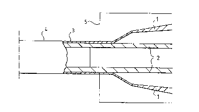
Fig. 1 depicts coating of a plastic pipe 2
according to the invention with a surface layer by co-
extrusion. The surface layer is formed from melt plastic
1 to provide a protective layer 3 around a pipe 2 of a
specified size. Coextrusion dies 5, e.g. so-called
crosshead dies, are known to one skilled in the art, and
coextrusion as such is not explained herein in greater
detail.
The protective outer layer according to the
invention is advantageously made easily detachable from
the core pipe by simple means, either wholly or only at
the joint surfaces, such as the pipe ends. In this way,

the surfaces remain in as good a condition as possible
for the seaming carried out by e.g. weldingl According
to a preferred embodiment of the invention, these objec~
tives are achieved by making the surface of the outer
layer moderately hard, whereby it has a low adhesion,
and to make the structure of the layer moderately stiff,
whereby the outer layer can be detached from the pipe
e.g. by knocking. For example, chalk and talc are suita-
ble fillers in respect of achieving this effect.
In a pipe 4 according to the invention the
plastics raw material used for the protective outer
layer 3 may be e.g. linear LDPE or even recycled plas-
tics waste. The advantage of the linear LDPE is its high
scratching and puncture resistance in view of its price,
whereas the advantage of the plastics waste is its low
price. When the material is selected, it is advisable
to take into account that if the outer layer is made
from plastics differing from the material of the core
pipe with respect to the chemical structure, the adhesi-
on between the pipe and the protective outer layer is
probably lower (they can be detached more easily) than
if exactly the same material is used.
According to another preferred embodiment of
the invention, the material of the outer layer 3 has at
least the same strength and/or stiffness as the material
of the core pipe 2. Thus the protective outer layer can
be a load-carrying component without having high re-
quirements set for the raw material (the price must be
as low as possible). Thus, cheap reinforcing andlor
stiffening fillers or fibres may be mixed to the mate-
rial of the protective layer. Alternatively, an outer
layer 7 may be stiffened in accordance with Fig. 2, by
ribbing or corrugations 6, to make the pipe 8 suffi-
ciently stiff. The ribbed outer layer 7 may be formed
e.g. in a gilled pipe machine or corrugating device.
,'

The protective outer layer can also be stif-
fened by foaming in a forming step, whereby the pipe
also acquires a considerable thermal insulation capaci-
ty.
Furthermore, the material of the outer layer
3 may advantageously be crosslinked in order to improve
the stiffness and strength and the resistance of the
outer layer of the pipe. In pipes reinforced in this
manner, the core pipe may be a thin-walled pipe or even
a hose, which is capable of resisting only internal
pressure caused by the fluid to be conducted, but which
would be flattened by earth pressure when laid in the
ground if not properly supported. The strength proper-
ties of the outer layer may also be made different in
the radial and axial directions of the pipe.
In a further embodiment of the invention, sla-
te-like mica is mixed with the material of the outer
layer to improve the barrier properties of the pipe. For
example, benzene compounds penetrate fairly easily
through a wall of a conventional tap water pipe made
from polyethene. When a mixture having good resistance
(barrier properties) to the penetration of the above
substances is selected as the material of the outer
layer, it is easy to tailor a tap water pipe for a spe-
cified aggressive chemical environment.
In yet another embodiment of the invention
barium sulfate is mixed with the material of the outer
layer to make the specific gravity of the pipe higher
than that of water. Barium sulfate (BaS04) has a!high
density, wherefore the overall density of e.g. a polyet-
hene pipe can be made higher than that of water. This
feature makes the pipe suitable for arrangements where
the pipe is laid in water.
In an additional embodiment of the invention,
easily magnetizable material or electrically conductive ~ ;
: . '

particles are mixed with the material of the outer layer
..
to r~nder the pipe detectable by a magnetic field. Exam-
¦ ples of magnetizable materials are iron oxide and barium
ferrite. In this embodiment the outer layer makes it
. . ~ .
possible to render the pipe laid in the ground easily
detectable by electromagnetic means. Mixed in a single-
layer pipe, fillers of this kind would reduce the
strength of the pipe.
In still a further embodiment of the invention,
electrically conductive material is mixed with the mate-
rial of the outer layer to render the pipe electrically
conductive. In an electrically conductive outer layer,
cracks occurring in the pipe line can be detected e.g.
by a cable fault finder. In addition, an electrically
conductive outer casing eliminates risks caused by indu-
ced electricity e.g. in an explosive environment. The
electrically conductive material may also be e.g. a
copper wire embedded in the outer layer.
In a still further embodiment of the invention
all the necessary identifying dyes and W stabilizing
agents are mixed with the material of the outer layer.
Thereby these pipe material-weakening agents need not
be mixed to the material of the actual conducting or
core pipe 2.
During the formation of the pipe it is possible
to introduce an adhesion inhibiting or enhancing agent,
depending on the use and the materials selected, between
the outer layer and the core pipe. In a preferred embo-
diment of the invention, a release agent, such as low
molecular weight polyethylene wax, is mixed with the
material of the outer layer to facilitate the detachment
of the outer layer from the core pipe 2. In another
embodiment, the core pipe is, prior to forming of the
outer layer, dipped in a bath containing liquid polymers

which act as an adhesion inhibiting layer between the
core pipe and the outer layer.
The outer layer can also be designed to be
detachable from the core pipe upon applying he~t to the
part of the outer layer to be removed.
If the core pipe is made e.g. from polyethene
and the outer layer from polypropene mixed with wax, the
outer layer is easy to detach from the core pipe. This
is particularly advantageous when the core pipe needs
to be easily replaceable (relining): the core pipe is
replaced by simply pulling it out from the outer layer
and inserting a new core pipe in the layer formed by the
outer layer.
It is also possible to introduce welding and/or
crosslinking enhancing agents between the outer layer
and the core pipe. Suitable welding enhancing agents
include e.g. dicumylperoxide. Crosslinking agents comp-
lement the crosslinking reaction of the pipe material
in the joint surface and provide lubrication, which is
advantageous in that it reduces the adhesion of the
protective layer. The crosslinking agents may be the
same generally known radicals that are used in the mat~
rix material of the pipe.
In a further embodiment of the invention, a
thin aluminum layer is provided between the outer layer
and the core pipe. The aluminum layer both facilitates
the detaching of the outer layer (in contrast to known
plastic aluminum laminates) and functions as a barrier
layer. In practice, a thin (0.1-0.3 mm) aluminum folio
is formed on the outer layer of the core pipe by adhesi-
on or ultrasonic welding.
A pipe according to the present invention is
advantageously seamed by peeling the outer layer off at
the area of the pipes to be seamed, and by subsequently
placing the pipes to be seamed together, and by carrying
~ ~'' ~,.; . ' .

: ~:
8 -~
out the seaming e.g. by electric welding. Thereafter the
seam is protected where necessary with a layer similar
to the outer layer, or left unprotected. In figure 3 is
I shown, by way of example, two identical pipes 9 accor-
ding to the invention, which are placed with their ends
positioned against each other at 10 in an electrofusion
pipe coupler device 11. The outer layers 12 of the pipes
has been removed from the cores 13 at the ends of the
pipes 9, in order to facilitate proper insertion and
welding of the pipes.
It is obvious to one skilled in the art that
the embodiments of the invention are not limited to
those described above, but that they may vary within the
scope of the attached claims.
~ ~ ' ". ''

Representative Drawing
A single figure which represents the drawing illustrating the invention.
Administrative Status

2024-08-01:As part of the Next Generation Patents (NGP) transition, the Canadian Patents Database (CPD) now contains a more detailed Event History, which replicates the Event Log of our new back-office solution.

Please note that "Inactive:" events refers to events no longer in use in our new back-office solution.

For a clearer understanding of the status of the application/patent presented on this page, the site Disclaimer , as well as the definitions for Patent , Event History , Maintenance Fee  and Payment History  should be consulted.

Event History

Description Date
Inactive: IPC expired 2019-01-01
Inactive: IPC from MCD 2006-03-11
Application Not Reinstated by Deadline 2005-08-12
Inactive: Dead - No reply to s.29 Rules requisition 2005-08-12
Deemed Abandoned - Failure to Respond to Maintenance Fee Notice 2004-12-24
Inactive: Abandoned - No reply to s.29 Rules requisition 2004-08-12
Inactive: Abandoned - No reply to s.30(2) Rules requisition 2004-08-12
Inactive: S.30(2) Rules - Examiner requisition 2004-02-12
Inactive: S.29 Rules - Examiner requisition 2004-02-12
Inactive: Office letter 2001-02-21
Letter Sent 2000-12-21
Inactive: Status info is complete as of Log entry date 2000-12-21
Inactive: Application prosecuted on TS as of Log entry date 2000-12-21
All Requirements for Examination Determined Compliant 2000-12-01
Request for Examination Requirements Determined Compliant 2000-12-01
Letter Sent 2000-02-10
Inactive: Multiple transfers 2000-01-20
Application Published (Open to Public Inspection) 1994-06-29

Abandonment History

Abandonment Date Reason Reinstatement Date
2004-12-24

Maintenance Fee

The last payment was received on 2003-12-04

Note : If the full payment has not been received on or before the date indicated, a further fee may be required which may be one of the following

  • the reinstatement fee;
  • the late payment fee; or
  • additional fee to reverse deemed expiry.

Patent fees are adjusted on the 1st of January every year. The amounts above are the current amounts if received by December 31 of the current year.
Please refer to the CIPO Patent Fees web page to see all current fee amounts.

Fee History

Fee Type Anniversary Year Due Date Paid Date
MF (application, 4th anniv.) - standard 04 1997-12-24 1997-11-26
MF (application, 5th anniv.) - standard 05 1998-12-24 1998-12-07
MF (application, 6th anniv.) - standard 06 1999-12-24 1999-11-25
Registration of a document 2000-01-20
Request for examination - standard 2000-12-01
MF (application, 7th anniv.) - standard 07 2000-12-27 2000-12-08
MF (application, 8th anniv.) - standard 08 2001-12-24 2001-11-19
MF (application, 9th anniv.) - standard 09 2002-12-24 2002-12-02
MF (application, 10th anniv.) - standard 10 2003-12-24 2003-12-04
Owners on Record

Note: Records showing the ownership history in alphabetical order.

Current Owners on Record
UPONOR INNOVATION AB
Past Owners on Record
ANDERS VESTERGAARD
JYRI JARVENKYLA
MIKAEL ANDERSSON
Past Owners that do not appear in the "Owners on Record" listing will appear in other documentation within the application.
Documents

To view selected files, please enter reCAPTCHA code :


To view images, click a link in the Document Description column. To download the documents, select one or more checkboxes in the first column and then click the "Download Selected in PDF format (Zip Archive)" or the "Download Selected as Single PDF" button.

List of published and non-published patent-specific documents on the CPD .

If you have any difficulty accessing content, you can call the Client Service Centre at 1-866-997-1936 or send them an e-mail at CIPO Client Service Centre.


Document
Description 
Date
(yyyy-mm-dd) 
Number of pages   Size of Image (KB) 
Representative drawing 1999-07-13 1 6
Claims 1995-06-02 5 394
Abstract 1995-06-02 1 48
Description 1995-06-02 8 593
Drawings 1995-06-02 2 130
Description 2001-01-07 8 364
Abstract 2001-01-07 1 18
Claims 2001-01-07 5 185
Drawings 2001-01-07 2 35
Reminder - Request for Examination 2000-08-27 1 116
Acknowledgement of Request for Examination 2000-12-20 1 180
Courtesy - Abandonment Letter (R30(2)) 2004-10-20 1 167
Courtesy - Abandonment Letter (R29) 2004-10-20 1 167
Courtesy - Abandonment Letter (Maintenance Fee) 2005-02-20 1 174
Correspondence 1994-04-04 18 737
Correspondence 2001-02-21 1 13
Fees 2000-12-07 1 36
Fees 1996-12-22 1 35
Fees 1995-12-12 1 37