Note: Descriptions are shown in the official language in which they were submitted.
-
211271 1
EIYDRAULIC ACTUATING SYSTEM FOR A FLUID TRANSFER APPARATUS
This invention relates to a hydraulic system for use in
actuating a stroking apparatus, and more particularly to an
actuating system for driving a pump jack in oil fields.
In the conventional walking beam type oil lift pump, the
5 drive system of which includes a prime mover having a constant
R.P.M. output driving through a gear box having a driven output
eccentric for oscillating the walking beam, the velocity prof ile
produced at the polished rod is substantially sinusoidal.
Because the well characteristics dictate the maximum speed of the
10 rod string at various points along the pumping cycle, adjustment
of the prime mover output to accommodate a low maximum speed at
one point in the pumping cycle affects speed during the entire
cycle. Because of the rigors which the pump jack must endure,
and because of the sophistication of adjustment required in
15 attempting to a~ te a par~icular speed profile customized
to a particular well, variable frequency drive mechanisms have
not met with success. Acceleration and deceleration results in
very high gear load.
In the pumping cycle of the rod string, which is attached to
20 the polished rod, maximum energy input is required during the
lifting stroke, and particularly during acceleration thereof
after having reached the lower most point of the stroke. In
fact, due to the weight of the rod string, a braking force must
be applied during the downward stroke of the polished rod,
25 meaning that the energy input to the system normally becomes
negative for this part of the pumping cycle, thus making it
2112711
possible, particularly when light oil i8 being pumped, to store
energy at this time. It is for this reason that in the older
conventional pump jack, a counterbalance weight was provided at
the end of the walking beam opposite to the connection of the
5 walking beam to the polished rod. Thus, during the downward
stroke of the walking beam, the weight on the walking beam is
raised to its maximum height so as to store energy which is
returned during the up stroke of the rod string and column of oil
to assist in its lifting. The velocity of travel of this type of
10 counterweight is also of a sinusoidal profile, and its actual
displacement is along an arcuate path of travel. Accordingly,
the timing of the return of the energy to the system is, like the
velocity prof ile of the output of the walking beam, f ixed.
In the more common type of walking beam pump jack now used,
15 counterbalance weights are mounted on the rotating arms which are
driven by the constantly rotating output shafts driven by the
gear box output shaft and to which there are connected the drive
rods attached to the walking beam. Thus, in this system the
counterweights are rotated through a complete cycle and therefore
20 store and retain energy along a very pronounced sinusoidal line.
The peak of the return of the energy from the counterweights thus
occurs when the rod string has been raised approximately one half
of its up stroke, i.e. when the counterweights are at a
horizontal position, which is about 90 out of phase with the
25 timing of required maximum input in the raising function.
Moreover, as the adjustments of the amount of counterweight
required for well conditions is a major and somewhat dangerous
~ 211271~
task requiring downtime of the pumping process in the weight type
counterbalance system, it is not uncommon for conventional pump
jacks to be allowed to run with the counterbalance functioning
well out of the optimum adjustment which couid be obtained with
5 such pu~p jacks.
The development of hydraulically driven pump jacks, of the
type shown in tAn~ n Patent No. 1,032,064, Minoru Saruwatari,
May 30, 1978, entitled "Pump Jack Device", has permitted the
customizing of the velocity profile of the polished rod to best
10 suit the well characteristics, and thus result in more efficient
and economical pumping of oil, particularly of heavy crude oil.
As well, it is feasible to utilize with such a hydraulically
driven pump jack a compressed gas counterbalance, which may be
mounted immediately on top of the main pump jack cylinder as
shown in Canadian Patent ~o. 1, 032, 064 or concentrically about
the hydraulic cylinder as shown in Canadian Patent Application,
Serial ~o. 615,238, Minoru Saruwatari, filed September 29, 1989,
entitled "Fluid Transfer Device" so as to provide a pump jack of
less height than that shown in the earlier patent. The
20 compressed gas type counterbalance has signif icant adyantages
over the weight type used in the conventional walking beam pump
jacks, particularly in the ability to adjust the amount of
counterbalance best suited to the well condi~ions while the pump
jack is operating. This is done by varying the gas pressure in
25 the counterbalance system. Such counterbalance systems have
experienced some problems, however, with regard to failure of
seals, due to the use of high pressures and because of the need
'
'~ 211271~
~o continuously operate the pump jack over long periods of time
under severe climatic conditions. Additionally while the amount
of energy in total which can in effect be reclaimed from the
system, up to a point, can be adjusted, the timing of the
5 reclaiming relative to the downward stroke and upward stroke, is
not variable. Thus, the ability to have the most effective use
of the stored energy in the counterbalance system, so as to
provide a more constant power input from the prime mover and also
to reduce strain on the pump jack, is limited. While using
10 compressed gas proviaes a better counterbalance system than is
possible in the counterbalance type using weights, however,
maximum efficiency is still not achievable.
It is an object of the present invention to provide a
hydraulic drive system for a stroking mechanism, such as used in
15 pump ~acks, which improves the usefulness of the counterbalance
and tllus reduces the power required from the prime mover, reduces
the stress on the drive system of the pumping components within
the well, and permits a pump velocity profile which is well
matched to the characteristics of the well.
The drive system of the present invention includ~s two
hydraulic closed-loop circuits. The first circuit consists of a
double acting drive cylinder means, a first pump and a pair of
fluid lines connecting the cylinder means and the first pump.
The cylinder means includes a pair of opposite fluid ports and a
stroking output means, and the pump is of the variable
displacement, reversible flow type, having a pair of opposite
fluid ports and an input shaft. The fluid lines connect the
~112711
ports of the cylinder means and of the pump so as to form a first
closed-loop hydraulic circuit. The second closed-loop hydraulic
circuit includes second and third pumps, each having an
input/output shaft, a pair of opposite fluid ports, and a second
5 pair of fluid lines connecting the ports of the second and third
pumps to form the second hydraulic closed-loop circuit. The
second and third pumps can function as a pump/motor means and at
least one of them is of the variable displacement type. The
system also includes a prime mover having an output shaf t means
10 drivingly connectea with the input shaft of the first pump in the
first hydraulic circuit and the input/output shaft of the second
pump in the second hydraulic circuit. A flywheel is drivingly
connected with the input/output shaft of the third pump for
receiving rotating drive therefrom and for transmitting drive
15 power thereto. The system further includes a control means for
establishing the setting of said first pump to establish the
quantity and direction of flow of fluid in the first closed-loop
circuit and to thereby determine the dLrection and velocity of
travel of the output means of the cylinder means, and for setting
20 the displacement within either the second or third pumps to
thereby establish the function of the second pump as a motor or a
pump~
Accordingly, the system of the present invention utilize6
the first closed-loop circuit to control the velocity profile of
25 the polished rod of the pump jack, which may be connected
directly to the output means of the drive cylinder means. While
energy may be directed from the prime mover, or even recaptured
2112711
from the first circuit during ~he downward travel of the polished
rod, as will be described in more detail below, and utilized to
increase the RPM of the flywheel. The energy thus stored due to
the increased velocity of the flywheel, is then available to be
returned to the fluid in the first closed-loop circuit through
the second closed-loop circuit by utilizing the second pump as a
motor Lor driving the first pump during upward travel of the
pol i shed rod .
Embodiments of the present invention are illustrated as
examples in the Acc~ nying drawings, wherein:
Figure 1 is an electrical/hydraulic schematic of one
embodiment of the drive system of the present invention;
Figure 2 is a schematic showing only the control means
isolating the control sensors, main controller and control valves
of the embodiment of Figure l;
Figure 3 shQws a simplified graph of a velocity profile of
the rod string, i.e. rod string velocity v. time;
Figure 4 is a view of an alternative form of the equal
displacement cylinder means of the present invention; and
Figure 5 is an enlarged vertical cross-section of the piston
and cylinder with the circle V of Figure 4.
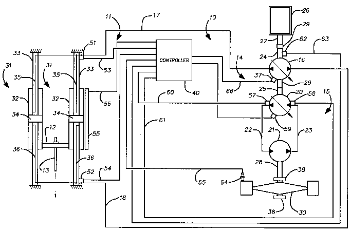
As shown in Figure 1, the reference number 10 denotes the
drive system of the present invention which includes an equal
displacement cylinder means 11 having an output means 12 for
attachment to a polished rod 13 of an oil well (not shown). The
system ll) includes two principal hydraulic circuits 14 and lS.
The first hydraulic circuit 14 includes a pump 16 and a pair of
2112711
hydraulic lines 17 and 18 connected between the pump 16 and the
cylinder means 11 to form a closed-loop hydraulic circuit. The
second hydraulic circuit 15 includes pumps 20 and 21 connected by
a pair of hydraulic lines 22 and 23 to form a second closed-loop
5 hydraulic circuit. Pump 16 has an input shaft 24, and pump 20
has an input/output shaft 25. A prime mover 26, which may be in
the form of an electric motor or an internal combustion engine,
has an output shaft 27. A drive connecting means 29 connects the
output shaft 27 of the prime mover 26 in a manner for driving the
10 input shaft 24 of pump 16 in the first circuit and the
input/output shaft 25 of the pump 20 in the second hydraulic
circuit. The drive connecting means 29 may also serve to connect
the input/output shaf t 25 of pump 20 in a manner to permit
transfer of driving power from pump 20, which is a pump/motor
15 means, to the input shaft of the pump 16. The pump 21 is also of
a pump/motor type and has an input/output shaft 28. A flywheel
30 is connected with the input/output shaft 28 for receiving
rotating drive therefrom or for transmitting driving power to the
pump 21. The flywheel 30 is shown as being fixed to a shaft
20 whicll is connected directly to the input/output shaf~ 28 and
mounted in bearings 38,38.
In t~le ~ o~l;r-~t of the hydraulic displacement cylinder
means 11 shown in Figure 1, it is in the form of a pair of
parallel hydraulic cylinder means 31, 31 of the through rod type
25 and wherein the cylinders 32,32 reciprocate. Through piston rods
33,33 are fixed or supported at opposite ends and are thus
stationary, as are the pistons 34,34 which are affixed to the
2112711
rods 33,33. The cylinders 32;32 are mounted for reciprocation in
unison and are connected by the output means 12 which is in the
form of a crossbar. One hydraulic line 17, which is in
communication with one port of the pump 16, is connected by way
5 of internal passages 35,35, which extend through the piston rods
33,33 to ports which are internal of the cylinders 32,32 above
the pistons 34,34. The other hydraulic line 18 is in
communication with the inside of the cylinders 32, 32 below the
pistons 34,34 via passages 36,36 in the piston rods 33,33. It
10 can be seen, therefore, that as the pump 16, which is of a
variable displacement, reversible flow type, is set on one side
of dead center to supply pressurized fluid to the upper side of
pistons 34,34, through line 17 and passages 35,35, while fluid is
allowed to return to pump 16 through passages 36,36 and line 18,
15 the cylinders 32,3~ are forced upwardly, thus imparting a lift
stroke to the polished rod 13 and the rod string attached
thereto. Alternatively, when line 18 is supplied with
pressurized fluid while fluid is permitted to return to pump 16
via line 17 from above the pistons 34,34, the cylinders are moved
20 to a lowered position.
It is of course possible to utilize a pair of through piston
rod type pistons, wherein the cylinders are stationary and the
piston rods reciprocate, as will be described in more detail
below in relation to Figure 4. Alternatively, a single cylinder
25 can be used which may be mounted directly above the well head
with the piston rod is aligned with and connected directly to the
polished rod. The reason a through piston rod type cylinder, or
~ 2112711
a pair of such cylinders mounted in parallel, is used is that in
a closed-loop circuit, the same amount of fluid must enter the
cylinder at one end as is simultaneously evacuated from the
opposite end to accomplish the up and down strokes. Alternative
arrangements are possible, such as the use of as pair of like
single ~iston rod cylinders, wherein one hydraulic line is in
communication with both the inner end of a first cylinder and the
outer end of a second cylinder, while the second of the pair of
hydraulic lines is connected to the outer end of the first
cylinder and the inner end of the second cylinder. With such an
arrangement one cylinder expands when the second contracts, but
the cylinders may be mounted in such a manner to rock a beam
which is connected to the polished rod. There are other
equivalent hydraulic mechanisms which would be obvious to one
skilled in the art, including a rotating hydraulic motor in the
closed-loop circuit in place of the illustrated through piston
rod cylinders, and wherein the rotating output of the motor is
translated into a reciprocating motion for stroking the polished
rod .
Referring now to Figures 4 and 5, hydraulic lines 17 and 18
are connected in a hydraulic circuit such as that shown in Figure
1, but the equal displacement cylinder means lla, include a pair
of parallel hydraulic means 31a, 31a wherein hydraulic cylinders
32a,32a are fixed instead of the piston rods of the earlier
embodiment. Through piston rods 33a, 33a, to which are affixed
piston 34a, 34a, within the cylinders 32a,32a, extend through
upper and lower ends of the cylinder 32a, 32a. EIydraulic line~
~ 2112711
17, which is connected to one port ol~ the pump 16 is connected to
ports communicating with the interior of the upper end of both
cylinders 32a,32a. E~ydraulic line 18, which is in communication
with the opposite port of pump 16 is connected to ports
5 communicating with the interior of both cylinders 32a,32a, at the
bottom end of the cylinders. An output means in the form of a
crossbar 12a is connected to both of the piston rods 33a, 33a, at
the upper ends thereof, and the polished rod, or a rod which is
connected to the polished rod of the well, is connected to the
10 crossbar 12a so that as the piston rods are forced up, the
polished rod is pulled up, and as the piston rods 33a, 33a are
caused to descend, the polished rod also moves downwardly thereby
causing the up and down strokes of the rod string.
In the ~mho~lir--lt shown in Figures 4 and 5, the portion of
15 each through piston rod 33a, which projects through the top of
the cylinder 33a, is under heavy compression during the upward
stroke, particularly after the turn around at the bottom of the
downward stroke of the rod string, and in fact, in most well
situations, the upper portion of the through piston rod remains
20 under considerable compression during the down stroke of the
polished rod. The structure illustrated in the enlargement
section view of Figure 5 allows for the use of a smaller piston
rod, which is thus lighter and less expensive, while providing
for higher power output for a cylinder of a given diameter.
25 While the outer diameter of the lower portion of the piston rod
33a, which extends through the bottom of the cylinder 32a, is the
same as the upper portion of the piston rod which extends up
2112711
through the top of the cylinder 32a, the upper portion, unlike
the lower portion, i5 not a solid rod but is in the form of a
tubular member or hollow rod 41. The hollow rod 41 remains full
of fluid 42 at all times, but this fluid is exposed to the
5 pressure of the fluid in the end of the cylinder which is being
subjected to the higher pressure at any instant. The existence
of the high fluid pressure in the interior of the upper portion
of the piston rod in effect applies a tension force to this
portion of the rod to at least partially negate the high
10 compression force on the rod and thereby resist buckling of the
upper portion of the piston rod.
The fluid 42 within the hollow rod is automatically
subjected to the pressure on either side of the piston 34a,
whichever pressure is higher, by way of the action of a shuttle
15 valve 43. A shuttle valve chamber 44 is connected by a passage
49 to the interior of the hollow rod 41, and the shuttle valve
chamber 44 has opposite ports 45,46 connected by passages 47 and
48 in the piston 34a to the fluid above and below the piston,
respectively. Accordingly, when the line 17 is receiving
20 pressurized fluid from pump 16, and line 18 is exhausting fluid
from below the piston 34a, a shuttle member 50 is forced against
port 46 to close passage 48. The shuttle valve chamber 44 and
fluid 42, via passage 49, is thus exposed to the high fluid
pressure above the piston through passage 47. Alternatively,
25 when line 18 is exposed to high pressure fluid and line 17 is
permitting the exhaust of the fluid above the piston 34a, the
~huttle mem~er so i~ oau~ed to everse It~: po~ition 90 al~ to
211271~
allow the higher pressure below the piston 34a to be exposed to
the fluid 42 within the hollow rod 41.
As indicated above the pump 16 is a variable displacement,
reversible flow pump, preferably of the swashplate type, wherein
5 the swashplate position is controlled by a control unit indicated
at 37. The pump further includes in combination with the control
unit an auxiliary pump (not shown) which draws fluid from a
systems reservoir (not shown) for make-up and control actuation.
The control unit receives an Electronic Displacement Control
lO signal (EDC) from a main controller 40 so as to position the
swashplate and thereby control the pump displacement and thus the
quantity of flow through one port to hydraulic line 17 while the
same quantity of flow enters an opposite port connected to
hydraulic line 18. Control of the quantity of flow in the
15 opposite direction in the closed-loop circuit 14 during the
opposite strolce of the polished rod is achieved as the swashplate
is moved across dead-centre and thereafter set at various
positions of displacement on the opposite side. As will be
described in more detail below, it is proposed that in most
20 installations, pump 16 will also be called upon to act as a
pump/motor unit so as to be able to utilize the circulation of
pressurized fluid in the closed-loop circuit 14 to drive its
shaft 24 whereby the shaft functions as an output shaft, and thus
termed herein as an input/output shaft.
Pump 20 of the second closed-loop circuit 15 is also shown
as a variable displacement pump which may be of the swashplate
type. While this pump need not be of the reversible type,
12
2112711
because the fluid in closed-loop circuit 15 always circulates in
the same direction, it is necessary that it be a variable pump
and be capable of acting as a pump or alternatively as a motor
driven by the fluid circulation, i.e. pump 20 must function as a
pump/motor. This pump's displacement setting is also controlled
by a control unit denoted 59, which receives a separate
Electronic Displacement Control signal (EDC) from the main
controller 40 so as to position the swashplate of pump 20 and
thereby control the quantity of flow of fluid therethrough. Pump
20, like pump 16, contains within its control unit an auxiliary
pump system for make-up and control actuation. Pump 20
performs as a pump when it is transferring energy into the
closed-loop circuit 15 and thus to the pump 21, or as a motor
when it is transferring energy out of closed-circuit 15 to the
input shaft of pump 16. In either mode the circulation of the
fluid in the circuit is in the same direction, i.e.
counterclockwi se .
Shown in the embodiment as viewed in Figure 1, pump 21 is
required to function as a motor when the fluid pressure in
hydraulic line 22 is above that in hydraulic line 23, and as a
pump when the relative pressures are reversed; thus this pump
can be termed a pump/motor as well.
When pump 21 f unctions as a motor driven by the circulated
fluid being pumped by pump/motor 20, the input/output shaft 28
functions as an output shaft to in effect store energy in the
flywheel 30 by increasing its speed (RPM). When the pump/motor
21 functions as a pump, its input/output shaft functions as an
13
2~127~ 1
input shaft, returning energy from the flywheel to drive the pump
21. The pumping of fluid into line 23 from line 22 increases the
pressure in line 23 and thus, the return of the energy into the
pressurized fluid from the flywheel decreases the flywheel speed.
5 Accordingly, in the embodiment shown, pump/motor 21
need not be either of a reversible flow or of a variable
displacement type, and thus it does not include a control unit
from receiving signals from main control 40 as in the cases of
pumps 16 and 20.
It should be apparent in view of the description of the
function of the overall closed-loop circuit 15 that the same
results could be obtained by switching the positions of pumps 20
and 21, i.e. by using a variable displacement pump with means for
control from main control 40 to transfer energy to or extract
15 energy from the flywheel. It is then possible to use a
pump/motor unit which is not of a variable displacement type for
automatically transferring energy to the circuit or transferring
energy to pump 16, depending on the relative fluid ~ressures in
lines 22 and 23 as established by the controlled pump/motor
2 0 connected to the f lywheel .
The system shown in ~igures 1 and 2 includes in its control
means a number of sensors for informing the main controller of
parameters existing in the system. The parameters are used by
the main controller 40 in conjunctiOn with programmed information
25 so the controller is capable of providing the EDC signals which
in turn establish the instantaneous settings of the displacemerrts
14
2112711
in pumps 16 and 20. The main controller 40, which may be in the
form of a personal computer with input/output ( I/O) boards added
to the expansion bus, is capable of monitoring various parameters
of the system to thereby control the velocity prof ile of the
5 polished rod which is its prime function. It further controls
the input of energy to and output of energy from the
counterbalance system which is in the form of the closed-loop
hydraulic circuit 15 and the flywheel 30 driven thereby.
There are depicted at 51 and 52 separate sensors for
10 providing signals via electrical lines 53, and 54, respectively
to inform the controller 40 of the hydraulic pressure in the
hydraulic lines 17 and 18, respectively, and thus the fluid
pressures above and below the piston 34,34 in the cylinders
32, 32 . These sensor may be mounted on the pump 16 and plumbed
15 into the opposite inlet/outlet ports thereof. These pressures,
provide information allowing the determination of a number of
values, including the lifting force in the cylinders 32,32 and
thus the polished rod load. The signals provided by the sensors
51,52 to the controller may be in the form of an ana~og voltage
20 or current. Also the pressures may be measured with the use of a
single sensor plumbed into a shuttle valYe connected across the
lines 17 and 1~.
A position encoder or sensor 55 is provided for measuring
the position of the cylinders 33,33 and supplying a signal via
25 line 55 to the controller 40, so as to give information
representative of the instantaneous position of the polished rod
2112711
in its pumping cycle. This stroke encoder or sensor 55 may be of
a type to produce a signal consisting of a minimum of three
separate signals, i.e. 3 digital channels. Two of such signals
will generate a quadrature output signal. By counting the number
5 of pulses generated, distance moved can be determined. By
measuring frequency o pulses, velocity can be determined and by
determining the phase between the two signals, direction of
motion can be found. Also, one or more signals are required to
indicate an index or reference position as the quadrature output
10 signals are not an absolute indication of position. As operation
of the system is initiated, the polished rod position is not
known by the controller ~0, and adjustment must be made to
establish a fixed reference position by way of information
provided from the sensor 55.
Pressure sensors 57 and 58 are provided in closed-loop
circuit 15, which may be plumbed into the opposite inlet and
outlet ports of the pump 20. Lines 60 and 61 connect the sensors
to the main controller so that signals produced by the sensors
are indicative of the pressures in hydraulic lines 22 and 23 and
20 are continuously supplied to the main controller for use in
determining, among other things, the EDC output of the controller
for setting the displacement of pump 20, and thus the energy
input into closed-loop circuit 15 or the energy transferred
therefrom. The signals provided from the sensors 57 and 58 may
25 be in the form of an analog voltage or current. Again, as an
alternative to the use of the two sensors 57 and 58, it is
16
-
2~1271~
possible to use a single sensor in combination with a shuttle
valve to obtain separate pressure readings from hydraulic lines
22 and 23.
It is further preferable to utilize A speed sensor 62 for
5 providing a signal which is indicative of the speed (RPM) of the
output shaf t 27 of the prime mover 26 . The sensor 62 may be of
the gear tooth type, and the signal provided thereby is fed to
the main control via line 63. Similarly, a speed sensor 64 is
used to supply a signal indicative of the flywheel speed (RPM),
10 the signal being transmitted to the main controller 40 via line
65. The RPM signals from sensors 62 and 64 may be in the form of
digital signals.
On installation of the pump jack system 10 on a particular
oil well, initial testing is conducted to establish an optimum
15 velocity profile for the rod string to achieve most efficient
pumping from the oil well. Various factors come into play.
To efficiently extract oil from a well, it is important to
complete each overall pumping cycle as quickly as possible so as
to achieve the maximum number of pumping cycles per unit of time.
20 The amount of time for one complete cycle ls shown at "a" in
Figure 3. Shown at "b" and "c" are the periods of time during
which the polished rod is travelling upwardly and travelling
downwardly, respectively. There may be dwell times "d" and "e",
between the end of the downward stroke and the start of the
25 upward stroke and between the end of the upward stroke and the
start of the downward stroke, respectively. A factor afEecting
17
2112711
the dwell time, for example, relates to the viscosity of the oil
being pumped, as the efficiency is decreased when the stroke
commences before the full quantity of oil has passed into the
downhole pump. Th~ length of the travel times "b" and "c"
5 depend, of course, on the rate of acceleration and deceleration
which can be used, those being shown as "f" and "g" for the lift
stroke and "h" and "i", respectively, for the down stroke. The
length of the travel time also depends on the maximum velocities
which can be used, as the higher the velocities, the shorter the
10 duration over time periods "j" and "k". The velocities may
remain substantially constant over these periods where "j"
repre3ents the maximum and constant velocity used during the lift
stroke and "i" represents the maximum and constant velocity used
over the down stroke. What represents acceptable acceleration
15 values and maximum velocity values is governed, of course, as to
what stress can be caused in the equipment, including the rod
string, to avoid costly maintenance. These values also depend on
the maximum power input available from the prime mover 26.
In the diagram of Figure 3, the constant velocity during the
20 period "k", which occurs during the downstroke of the polished
rod, is shown as being equal to that which occurs, except in the
opposite direction, during the lift stroke at " j" . Such a
situation may not be possible in all wells, since in heavier
crude oils, the descent of the rod string, which cannot be
25 forced, may occur at a rate which is below that at which the lift
stroke occurs. Moreover, due to the stretch of the rod string
18
2112711
which is significant in a long rod string, the movement of the
downhole end of the rod string does not coincide, time wise, with
that of the polished rod. While it may be possible to take some
advantage of the rod stretch to achieve certain pumping
S characteristics, it doe~ affect the optimum velocity profile
selected for the polished rod, and as the rod stretch does
represent a storage of energy, it also has an affect on
requirements of the counterbalance system with respect to the
time and amounts of the energy input and output of the system.
10 In any event, as indicated above, the maximum velocities will be
established which allow the pump jack to operate at the maximum
velocities without exceeding the system' s limits . The rod string
minimum and maximum loads, as well as the upper power limit of
the prime mover, can be programmed into the main controller. If
15 at any time in the total stroke cycle these limits are exceeded,
the main controller can react by reducing the velocity of the rod
string .
Considering first, a situation where exceptionally heavy
crude oil is not being pumped so that the oil viscosity is such
20 that under free fall the rod string would significantly exceed
the velocity indicated for the duration "k" of Figure 3, it is
obvious that the counterbalance system can function to receive
energy from the pump jack for storage in the rotating flywheel.
First, however, one might consider the pumping cycle as
25 experienced by the polished rod, the velocity of which has been
programmed to follow the line as shown in Figure 3, starting at
19
.
2112711
the dwell "d" immediately preceding the acceleration for the lift
stroke. At this point, the flywheel will be rotating at a high
speed for reasons which will become apparent below, and its RPM
will be known by the main controller 40 by way of sensor 64.
5 Also the output shaft 27 of the prime mover 26 will be rotating,
and the rotation of this shaf t may be substantially constant at
all times, particularly if the prime mover is an electric motor.
In any event, the main controller 40 will also be aware of the
RPM of shaf t 27 by way of sensor 62 .
The drive connection means 29 may be a gearbox dri~en by
output shaft 27 and having a pair of output shafts connected
directly to the shafts 24 and 25 of pumps 16 and 20,
respectively, instead of being connected only to input shaft 24
of pump 16 as shown in Figure 1. Such a gearbox may be designed
15 so that it has two output shafts which rotate at the same speed,
but in any event the input shafts of each of pumps 16 and 20 wil
be rotated at a speed which directly relates to the known speed
of output shaft 27 of the prime mover 26. As the drawings
indicate, however, there are in fact commercially available
20 variable displacement pumps of the type required in such an
installation for connecting together in a twinned fashion so that
the shafts are attached for rotation together. Thus, as shown,
only one pump such as pump 16 would be drivingly connected to the
output shaft 27 or to an intermediate gearbox 29 driven by the
25 prime mover 26.
In the illustrated embodiment, the prime mover 26 will have
2~12711
a known optimum maximum power output which will be programmed
into the main controller, and because of the presence of the
counterbalance system represented by the second hydraulic circuit
15, this maximum power output may be significantly less than that
5 required to accelerate the polished rod and to drive it at the
maximum velocity as indicated for the durations "f" and "j",
during the lift stroke. The main controller 40 will be
programmed, nevertheless, to provide at this point an EDC 6ignal,
via line 66, to the control unit 37 of pump 16, to increase the
10 displacement of the pump in a direction to cause pressurized flow
into line 17 and to draw fluid from line 18. As illustrated in
Figure 2, the electrical current signal sent to control unit 37
energizes a variable solenoid 67 which actuates a proportional
valve 68. The solenoid and proportional valve are part of the
15 control unit 37 and as the valve 68 is shifted, a flow of fluid
is effected to shift the posi~ion of the swashplate of pump 16.
Thus, a known change in the electrical current which forms the
EDC signal is translated into a predetermined amount of shifting
of the swashplate, which in turn varies the pump displacement to
20 cause the instantaneous quantity of flow into line 17 from line
18 to bring about the upward displacement of cylinders 32,32
causing the rate of acceleration of the polished rod as indicated
for the duration "f". When the velocity shown at the level
indicated during period " j" is reached, the swashplate position
25 of pump 16 is maintained by the EDC signal to pump control unit
~ 21127~1
37 to provide the optimum, substantially constant velocity until
the upper end of the stroke is approached. The EDC signal via
line 66 from the main controller 40 then ~rovides for a shift of
the swashplate in the pump 16 to decelerate the polished rod to a
5 stop. After the dwell time "e", the swashplate of pump 16 is
passed over centre to commence the flow from line 17 to line 18
at a rate to achieve acceleration of the polished rod for the
duration "h". Having reached the maximum velocity as represented
by the flat line of the duration "k", the flow is maintained at a
10 rate to maintain that velocity, followed by a shift of the
swashplate back towards the neutral position for deceleration as
the polished rod reaches the bottom of the stroke. As the
swashplate reaches its dead-centre position, this completes the
full cycle of the polished rod, and subsequently the upward
15 ~troke is, e ~r~d as previously described.
The instantaneous load being applied to raise the polished
rod 13 by the upward movement of cylinders 32,32 is known because
of the information of pressure above and below the piston of both
cylinders as sensed by sensors 51 and 52, respectively. The
20 controller 40 is also aware of the upward velocity because of the
information provided by the sensor 55, as described above. The
amount of power input to the pump jack at any instant via pump 16
is thus calculable from the velocity and pressure readings. As
well, the value of the EDC to the controller 37 is a direct
25 indication of the swashplate setting and thus the displacement of
the pump. The quantity of flow in the circuit 14 is directly
22
~ 2112711
related to the displacement and pump RPM, and together with the
pressure readings of lines 17 and 18 erovide a source of
information to the main controller 40. The controller is
programmed to maintain information of previous pumping cycles and
5 can thereby verify the correctness of the EDC output, for
example, and make on the run adjustments if necessary. Also, as
previously indicated, if external conditions change, such as the
requirement of a greater load to achieve the previously set
maximum upward velocity of the polished rod, the velocity may be
10 reduced, for example, or a system shut down is indicated if the
change is severe.
It is desirable for equipment longevity and low operating
costs to operate the prime mover 26 at a relatively constant
power output. The main controller 40 can be programmed to
15 achieve this by controlling energy flow via pump 20 into the
second hydraulic circuit, including the flywheel 30, and the flow
of energy therefrom at seeclfic required times. ~escribing the
energy requirements for a relatively simele eumping cycle, where
the crude oil is relatively light, and settings are not made to
20 take into account rod string stretch, the amount of power
required at the beginning of the ueward stroke, as discussed
above, increases very rapidly for acceleration. The power input
to the f irst hydraulic circuit 14 then remains substantially
constant, but relatively high during the time period "j", and
25 falls off quickly during deceleration at the end of the upward
stroke. As described, the main controller 40 is supelied with
2112711
information continuously, which allows it to maintain the desired
velocity profile for the polished rod and to simultaneously
calculate from this information and that which has been
programmed into the main controller, exactly what energy is
5 required in total at any instant. The controller is thus able to
determine what power need be added to that being supplied by the
prime mover 26 so that the prime mover 26 preferably does not
have to signif icantly vary its output. Thus, the controller 40
provides an EDC output signal to the control unit 59 of pump 20
10 which has a variable solenoid 70 and a proportional valve 71
which functions in substantially the same manner as the
corresponding components of control unit 37. The swashplate of
the pump 20 need not be of the type to pass over centre as the
direction of flow in the second hydraulic unit 15 is always in
15 the same direction. The magnitude of the signal, however,
controls the position of the swashplate to vary the displacement
of the pump 20, and thus the quantity of flow in the single
direction .
Because the energy input to the pump jack to commence
20 raising the polished rod is high, the EDC signal provided from
the main controller 40 to the control unit 59 of the pump 20
causes a shifting of the swashplate of this pump so as to vary
the pump's displacement to a degree that the fluid pressure in
line 23 is higher than that in line 22. To this point pump 21
25 had been driven by the fluid circulating in circuit 15, for
increasing the rotational speed of the flywheel 30, i.e. it
24
211271~
performs the function of a motor. Pump 21 now commences to
function as a pump, and thus, as the flywheel 30 drives pump 21,
energy is extracted from the flywheel to pressurize the -fluid
delivered to line 23, which energy is extracted from the fluid as
5 it drives pump 20 as a motor. The output power derived from this
energy drives shaf t 25 which adds to the input of prime mover 26
for meeting the energy input required by pump 16. The pump 16,
in turn, meets its committment, as set by the setting of this
pump by the main controller 40, via the EDC signal delivered to
10 the control unit 37 of pump 16. This EDC signal is determined,
as explained above, to establish the desired velocity profile of
the polished rod. The EDC signal provided by the main controller
40 to the control unit 59 of pump 20 is determined by the main
controller to set the swashplate of pump 20, now functioning as a
15 motor, to extract from the momentum of the flywheel 30, energy
through the pumping of pressurized 1uid to line 23, sufficient
to ensure that the load placed on the primer mover 26, during the
duration "f" and then "j", and possibly part of the duration "g"
does not exceed the designated maximum load of the prime mover
20 26. Depending on the requirements of the input to the pump jack,
and the amount of energy which can be collected during the
remainder of the pump cycle, as will be described in more detail
below, the amount of energy extracted from the counterbalance
system during the upstroke of the polished rod, may in fact,
25 allow the prime mover 26 to operate at a constant power output.
This output may be at a load considerably below that of its
2112711
allowable maximum.
In the type of installation being described, once the
polished rod ~ c,oC its downstroke, the force caused by the
weight of the string rod will in effect be braked by the fluid in
5 the cylinders 32,32 above the pistons 34,34, resulting in the
pressure in line 17 being above that in line 18. The downward
acceleration of the polished rod for duration "h", the constant
downward velocity of the polished rod for the period "k", and
then the deceleration for the duration "i" are all again
10 controlled by the setting of the swashplate of the pump 16 by the
EDC signal received from the controller. During these durations
the swashplate setting is on the opposite side of dead centre
than during the upward stroke, and the pump 16 is being driven,
so as to be functioning as a motor. Due to the interconnection
15 of the shaft 24 and 25 of the pumps 16 and 20, the output power
derived from the pump 16 controlling the flow of the high
pressure fluid from line 17 to the lower pressure line 18, is
transferred to pump 20. The EDC signal received from the main
controller 40 by the control unit 59 establishes a setting for
20 pump 20 so that the pump establishes a higher pressure in line 22
than in 23, i.e., it again acts as a pump instead of a motor.
This causes pump 21 to function as a motor in that it receives
fluid at a higher pressure than what is delivered to line 23.
Acting as a motor, it ~ ce~ to again increase the speed of
25 the flywheel, which had been slowed during the upstroke of the
polished rod. Moreover, as an energy input is not required by
26
2112711
pump 16 from the prime mover, the setting of the displacement of
the pump 16 is such to provide an output speed of its shaft 24 in
relation to the output speed of the shaft 27 of the prime mover,
that the output power of the prime mover 26 is also transferred
5 to the shaft 25, which at this time is acting as an input shaft
of the pump 20. By properly balancing the amount of energy
stored in the flywheel 30 and the desired output of the prime
mover 26 with the total energy required during the upstroke of
the polished rod, the output power of the prime mover required
10 during the upstroke can be substantially equalled to that needed
to be added to the counterbalance system during the downstroke.
If an installation involving the pumping of exceptionally
- heavy crude oil is now compared with the above, it is possible
that because of the slowness of the rod string returning from its
15 raised position, very little braking is required by the
resistance provided by the pump 16 functioning as a motor for at
least some of the total duration of "h" + "k" + "i". This would
mean, of course, that little or no energy is returned from the
first circuit 14 to what has been referred to as the
20 counterbalance circuit 15 during the downstroke of the polished
rod. Nevertheless, the second circuit 15 is still capable of
performing the important function of storing energy provided by
the prime mover 26 during the downstroke. As the second circuit
is then functioning more as an energy conservation circuit, its
25 function is less as a counterbalance system as such. The
usefulness of the system used in this manner is nevertheless
27
21127 l 1
clear in that the energy used during the upward stroke is derived
from both the prime mover and the second circuit 15, again
allowing the energy input from the prime mover 26 to remain
substantially constant and at a level considerably below the
S maximum energy level required during the upstroke.
It is apparent, however, the lower the viscosity of the
crude being pumped, the more energy utilized in raising the rod
string can be retrieved by the f irst circuit and returned to the
counterbalance circuit. The counterbalance or second hydraulic
10 circuit may be simultaneously storing energy from the prime mover
26 which is not required in the first circuit during the
downstroke. As the viscosity of the crude in a well becomes
higher, ~he second circuit may derive less energy being retrieved
from the downstroke in the pump jack, but nevertheless it is
15 fully capable of storing energy to allow the use of a smaller
prime mover and avoid higher peak inputs.
In the disclosed P~ho~;r-~t~ the main controller 40, in
combination with the f irst hydraulic circuit 14, is capable of
providing a customized velocity profile for the polished rod and
20 also a return of energy retrieved from the downstroke of the rod
string to the second circuit. The main controller 40, in
combination with the second circuit, is capable of storing energy
retrieved by the first circuit and/or directly from the prime
mover whenever such energy is available, and then returning it to
25 the first circuit at whatever time it is most efficient to do so.
While an embodiment of the invention has been described
28
2112711
above as an example of the preset invention, alternatives within
the inventive concept as def ined in the appending claims will be
obvious to those skilled in the Art.
29