Note: Descriptions are shown in the official language in which they were submitted.
- 2112722
This invention relates to load bearing support
columns, and in particular to an adjustable lifting and
shoring jack assembly.
Adjustable support posts or columns are well known
in the art. Typically, conventional support columns, such as
lifting jacks for lifting and supporting of various structures
employ a single, threaded support rod disposed in a main
column. Many of these assemblies comprise a main column
composed of two or more telescoping elements which can be
extended and locked at predetermined intervals, such that the
column can be adjusted to a length which is slightly shorter
than that which is actually required. The threaded support
rod, which may either engage an internal screw in the main
column or an adjusting nut which bears on the top of the
column, is then extended as required to support and/or raise
the structure in question.
For example, United States Patent No. 3,027,140
(Holzbach) discloses an adjustable element which is adapted
to be quickly and removably fitted to a fixed length columnO
The disclosed adjustable element comprises an adjusting screw
and nut, a bearing plate, and a base plate. The adjustable
element is intended to be used in conjunction with a column
or post which is obtained separately, and cut approximately
to length, by the user, on site.
However, in some cases it is necessary to raise the
structure by a substantial distance. For example, when a
house or other structure is jacked to permit moving of same,
or to raise its foundation, it is frequently found to be
necessary to raise the structure by one metre or more.
However, conventional jack posts of the type disclosed in
United States Patent No. 3,027,140 tend to become unstable,
and prone to buckling, due to the extreme length of the
adjusting screw extending from the fixed length column
portion.
United States Patent No. 4,872,634 (Gillaspy et al)
discloses a brace assembly which consists of a main brace and
a pair of side braces pivotally attached thereto. The length
2112722
of the main brace is adjustable by means of threaded couplings
mounted on the ends thereof. Each of the threaded couplings
consists of a length of threaded rod slidably fitted within
the hollow main brace, and a nut which bears against an end
surface of the main brace. A mounting bracket is pivotally
fitted to the free end of each of the side braces to permit
the side braces to be attached to a portion of a member being
supported (i.e. a wall), or to some other structure (such as
a floor), so as to lend stability to the main brace.
However, since the side braces are of fixed length,
the extent to which the main brace can be extended after the
side braces have been attached is severely limited.
Accordingly, a supporting system such as that disclosed in
United States Patent No. 4,872,634 is of limited use in
situations where a structure being supported must be lifted
through a substantial distance.
Finally, when used to support a structure of
substantial weight, a jack post tends to be forced downwards
into the earth. Typically, the base plates provided on
conventional jack posts do not distribute the weight over
sufficient surface area to prevent from undue sinking of the
post into soft and/or unprepared earth. Thus the safe and
effective use of conventional jack posts is often impossible
under these conditions.
It is therefore an object of the present invention
to provide an adjustable lifting and shoring jack assembly
capable of lifting a load through a substantial distance, and
which can be safely and effectively used on soft and/or
unprepared earth.
According to an aspect of the present invention,
there is provided a lifting and shoring jack assembly
comprising: baseplate means, said baseplate means being
capable of distributing load forces over a sufficiently large
surface area to substantially prevent said jack assembly from
sinking into soft earth when subjected to a load; support
column means removably disposed on said baseplate means; jack
screw means slidably disposed within said support column means
~ll2722
_. 3
and at least partially extending therefrom; jack nut means
operatively engaged with said screw means, and bearing on an
end surface of said support column means; load plate means
disposed on a free end of said screw means and capable of load
bearing engagement with a load to be supported; and at least
two side brace means pivotally connected to said column means,
each of said side brace means comprising: a respective
elongate brace arm pivotally connected at an end thereof to
said support column means; respective length adjusting means
disposed at a free end of each of said brace arms for
adjusting the length of each of said brace arms; and
respective load engaging means pivotally disposed on said
respective adjusting means to facilitate load bearing
engagement between the load to be supported and each of said
side brace means.
In a preferred embodiment, the column means is
removable from the base plate means, thereby permitting the
assembly to be disassembled for ease of storage and
transportation.
In a further preferred embodiment, the lifting and
shoring jack assembly is further provided with a second
supporting column comprising secondary support column means
removably disposed on said baseplate means; extension screw
means slidably disposed within said secondary support column
means and at least partially extending therefrom; extension
nut means operatively engaged with said extension screw means,
and bearing on an end surface of said secondary support column
means; and jack means disposed on a free end of said screw
means and capable of load bearing engagement with a load to
be supported.
Preferably, the jack means is a hydraulic jack.
Further objects, features and advantages of the
invention will become apparent from the following description
of a preferred embodiment when read in conjunction with the
accompanying drawings, in which:
Figure 1 is a perspective view illustrating a first
embodiment of the present invention;
2ll2722
Figure 2 is a side view showing the embodiment of
Figure 1 in cross-section;
Figure 3 is a perspective view illustrating a second
embodiment of the present invention;
Figure 4 is an elevation view illustrating an
embodiment of the present invention in use for supporting and
raising a building; and
Figure 5 is a plan view illustrating the placement
of several jack assemblies according to the invention in
relation to a building being supported and raised.
It should be noted that throughout the figures, like
elements are identified by like reference numerals.
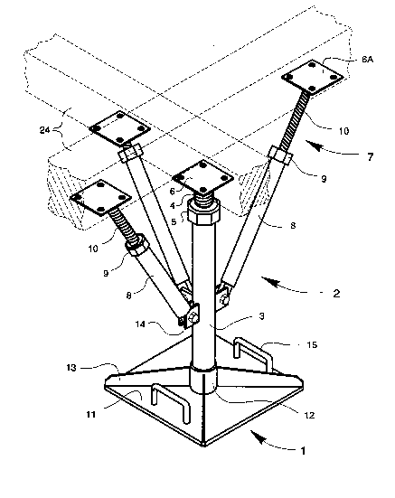
Referring to Figures 1 and 2, the jack assembly
comprises a baseplate 1, and a main support assembly 2. The
main support assembly 2 comprises a hollow main column 3
mounted on the baseplate 1, a jack screw 4 slidably disposed
within the main column 3 and at least partially extending
therefrom, a jack nut 5 in threaded engagement with the jack
screw 4, and bearing on the end surface of the main column 3,
and a load plate 6 mounted on the exposed free end of the jack
screw 4. At least two side braces 7 (three are illustrated
in Figure 1) are pivotally mounted on the main column 3. Each
of the side braces 7 are designed to be adjustable in length
as the load to be supported (diagrammatical represented in
Figure 1 by beams 24) is raised by the main support assembly
2, and include a respective load plate 6a which facilitates
engagement with the load to be supported. Conveniently, the
side braces 7 can have a construction similar to that of the
main support assembly 2, in that they can comprise a hollow
brace arm 8 pivotally connected to the main column 3, a length
of threaded rod 9 slidably mounted within the brace arm 8, and
an adjusting nut 10 in threaded engagement with the threaded
rod and bearing on the end surface of the brace arm 8.
The baseplate can have any desired configuration,
provided that it offers a large "footprint", so that heavy
loads can be securely supported by the jack assembly, even
when used on soft and/or unprepared earth. Conveniently, the
'21~2722
baseplate 1 will consist of a generally square or rectangular
bottom plate 11, a centrally-located column seat 12 for
receiving the main column 3, and a set of generally radially
oriented stiffening ribs 13 for transferring load forces
outward towards the periphery of the bottom plate 11. The
bottom plate and stiffening ribs 13 can conveniently be
constructed of steel plate, and the column seat 12 from hollow
round structural steel, the entire baseplate 1 being fastened
together by, for example, welding.
The interior diameter of the column seat 12 is
suitably sized with respect to the outside diameter of the
main column 3, so that the main column 3 is held securely
therein during use of the jack assembly, but can be readily
removed therefrom for ease of transportation. However, the
main column 3 can be permanently fastened in the column seat
12, for example by means of welding, in cases where
disassembly for ease of transportation is not a consideration.
The main column 3 is conveniently constructed of
hollow tubular steel, and will be sized appropriately
according to the loads to be supported. Similarly, the jack
screw 4 and jack nut 5 will be suitably sized according to the
load to be supported. In addition, the outer diameter of the
~ack screw 4 will be selected to provide a clear sliding fit
within the main column 3. However, the fit between the jack
screw 4 and the interior of the main column 3 must be close
enough to substantially prevent an angular offset between the
main column 3 and the Jack screw 4 (with the attendant
increased bending stresses and risk of buckling). The length
of the jack screw 4 will be selected according to the desired
distance through which the load is to be lifted, but can
conveniently be approximately the same length as that of the
main column 3, thereby allowing jack assembly to lift the load
to be supported through a distance as close as possible to the
height of the main column 3.
Each of the side braces 7 is pivotally attached to
the main column 3 by means of respective pins or bolts and
support lugs 14 attached to the exterior of the main column
2112722
3 (for example by means of welding) so as to not interfere
with movement of the jack screw within the main column 3.
In use, the jack assembly is located under a load
to be supported (see Figure 4), and the load plates 6 and 6a
of the main support assembly 2 and side braces 7,
respectively, are attached to the load to be supported, such
as a building 26 and/or temporary support beams 24 located
under the building 26 to facilitate the jacking thereof (note
that in figure 4, only one side brace 7 is shown for
clarity.). If desired, the base plate 1 can be secured
against lateral (sliding) movement by the use of stakes 26
driven into the ground. The jack screw is then turned in a
direct to extend the jack screw 4, from the main column 3, so
as to raise the load to be supported, through a desired
distance. As the load to be supported is raised by the main
support assembly 2, the threaded rods 9 of the side braces 7
are pulled outwards from their respective brace arms 8. As
this occurs, the adjusting nuts 10 are turned in order to
maintain each of the side braces in compression, so that at
least some of the weight of the load being supported is
transferred to the main column 3 through the side braces 7.
The maintenance of a compressive loading in each of the side
braces 7 serves two purposes. First, it reduces the load
forces acting on the jack screw 4 and jack nut 5, thereby
making the jack nut 5 easier to turn. Second, the forces
exerted by the side braces on the main column 3 tend to brace
the main column 3 against bucking, thereby increasing the
effective load carrying capacity of the jack assembly of the
invention.
Figure 3 illustrates a second embodiment of the jack
assembly of the present invention. This second embodiment
retains the base plate 1, main support assembly 2, and side
braces 7 described in respect of the first embodiment~
Accordingly, these elements will not be further discussed in
detail. The lifting and shoring jack assembly, according to
the second embodiment of the invention, is provided with a
secondary support assembly 16 comprising a secondary support
2 1~'~722
~_ 7
column 17 mounted on the baseplate 1; an extension screw 18
slidably disposed within the secondary support column 17 and
at least partially extending therefrom; an extension nut 19
engaged with the extension screw 18 and bearing on an end
surface of the secondary support column 17; and a lifting jack
20 mounted at the top of the extension screw 18.
The secondary support column 17 is preferably
mounted on the baseplate 1, by means of a secondary support
column seat 21 in essentially the same manner as the main
column 3. In addition, the secondary support column 17 is
removably coupled to the main column 3, at least during use,
by means of a bolt (or the like) and lugs 22 affixed near the
top of secondary support column 17 and the main column 3.
The operation of the jack assembly according to the
second embodiment of the invention is essentially the same as
that of the first embodiment, except that in this case, the
lifting jack 20 (which preferably comprises a conventional
hydraulic or pneumatic jack) is used to lift the load being
support through a small distance; the jack nut 5, and
adjusting nuts 10 are the tightened so that the main support
assembly 2 and side braces 7 carry the weight of the load
being supported; the lifting jack 20 is then released so that
the extension nut 19 can be turned to extend the extension
screw 18, thereby raising the lifting jack 20 without lifting
the load being carried. By this means, the load being
supported can be raised through a series of comparatively
small incremental steps, thereby ensuring safe operation of
the jack assembly.
As a further safety measure, additional side support
lugs 23 can be provided near the top of the main column 3.
These additional lugs permit a further set of side braces 7
to be mounted on the main column 3, thereby increasing the
buckling resistance of the main support assembly 2. In
addition, the baseplate 1 can be modified as desired to
provide additional reinforcement to the central portion of the
bottom plate 11, particularly under the main support assembly
2 and the secondary support assembly 16.
2112722
Figures 4 and 5 illustrate the use of the jack
assembly according to the present invention for supporting and
raising a building 25. Figure 4 presents an elevation view
of a jack assembly being used, while Figure 5 presents a plan
view showing the general locations of each of the jack
assemblies used, along with supplementary supporting beams or
timbers 24 and bracing stakes 26 in relation to the building
25 being supported and lifted.
In order to ensure adequate support of the building
25, while it is being lifted, a set of lateral and
longitudinal support beams (or timbers) 24 are preferably
provided under the building 25. A number of jack assemblies
(in the present example, six are employed) are then installed
such that the main support assemblies 2 thereof are positioned
under the respective intersection points of the beams 24. At
this point, side braces 7 are mounted on each of the
respective main support columns 3, and attached to the beams
24, generally as illustrated in Figures 1, 4 and 5. Following
the installation of the beams 24 and jack assemblies, in this
manner, the building 25 can be raised by operating each of the
jack assemblies in the manner described above in connections
with Figures 1-3. In tests performed by the inventor, two
houses (one measuring approximately 30' by 40') were
successfully raised by this method. During one of these
tests, the house in question was subjected to winds in excess
of lOo km/hr without ill effect.