Language selection

Search

Patent 2112813 Summary

Third-party information liability

Some of the information on this Web page has been provided by external sources. The Government of Canada is not responsible for the accuracy, reliability or currency of the information supplied by external sources. Users wishing to rely upon this information should consult directly with the source of the information. Content provided by external sources is not subject to official languages, privacy and accessibility requirements.

Claims and Abstract availability

Any discrepancies in the text and image of the Claims and Abstract are due to differing posting times. Text of the Claims and Abstract are posted:

  • At the time the application is open to public inspection;
  • At the time of issue of the patent (grant).
(12) Patent: (11) CA 2112813
(54) English Title: ROTARY CUTTER FOR EXTRACTING HARD ROCK
(54) French Title: FRAISE ROTATIVE POUR L'EXTRACTION DE ROCHES DURES
Status: Expired and beyond the Period of Reversal
Bibliographic Data
(51) International Patent Classification (IPC):
  • E21C 25/16 (2006.01)
  • E02F 3/24 (2006.01)
  • E21C 47/10 (2006.01)
(72) Inventors :
  • FLEISCHHAKER, WOLFGANG (Germany)
  • METT, JOACHIM (Germany)
(73) Owners :
  • KRUPP FORDERTECHNIK GMBH
(71) Applicants :
  • KRUPP FORDERTECHNIK GMBH (Germany)
(74) Agent: MACRAE & CO.
(74) Associate agent:
(45) Issued: 2000-06-13
(86) PCT Filing Date: 1992-06-23
(87) Open to Public Inspection: 1993-01-21
Examination requested: 1994-06-07
Availability of licence: N/A
Dedicated to the Public: N/A
(25) Language of filing: English

Patent Cooperation Treaty (PCT): Yes
(86) PCT Filing Number: PCT/EP1992/001410
(87) International Publication Number: WO 1993001392
(85) National Entry: 1994-01-04

(30) Application Priority Data:
Application No. Country/Territory Date
P 41 23 307.7 (Germany) 1991-07-13

Abstracts

English Abstract


Proposed is the use of a wheel-shaped
rotary cutter for the continuous working of hard
mineral-rock beds with a cylinder crushing resistance
of greater than or equal to 20 MPa, the
cutter being fitted both round its circumference
and at the sides with a multiplicity of cutting
elements. The cutter is driven to operate in the
vertical plane, powered by a generator with an
installed rating of at least 0,3 kW per theoretically
calculated cubic meter of rock extracted
per hour.


French Abstract

Il est proposé l'utilisation d'un outil de fraisage à disque pour l'extraction en continu de couches de roche minérales dures avec une résistance à l'écrasement cylindrique supérieure ou égale à 20 MPa, l'outil de fraisage étant muni tant sur sa circonférence que sur ses faces frontales d'une pluralité d'éléments de coupe. L'outil de fraisage est utilisé en trait d'abattage, en coopération avec un équipement moteur présentant une puissance installée d'au moins 0,3 kW par m3/h de puissance d'extraction théorique.

Claims

Note: Claims are shown in the official language in which they were submitted.

THE EMBODIMENTS OF THE INVENTION IN WHICH AN EXCLUSIVE
PROPERTY OR PRIVILEGE IS CLAIMED ARE DEFINED AS FOLLOWS:
1. A rotary cutter for continuous excavation of hard
mineral rock layers, comprising: a. disk-shaped supporting
element having a pair of axially spaced, annular ring supports
adjacent the periphery thereof; a plurality of
circumferentially spaced apart stirrup-shaped cutting elements
formed integrally with said ring supports; and at least one
stock guiding pouch between each pair of said cutting
elements.
2. The rotary cutter of claim 1 wherein there are at
least thirty-two of said cutting elements spaced apart on said
supporting element and wherein each said cutting element
includes at least four cutting teeth.
3. The rotary cutter of claim 1 or claim 2 including
a drive assembly therefor producing an installed power of at
least 0.3 kW per m3/h of theoretical conveying power and
wherein said rotary cutter provides a cylindrical compressive
strength of equal to or greater than 20 MPa.

Description

Note: Descriptions are shown in the official language in which they were submitted.


2112813
-1-
The invention concerns a disk-shaped milling tool for mining layers
of hard mineral rock.
Background of the Invention
A procedure for mining limestone (marl) is described in DE-OS 38 22
200, whereby the limestone is extracted in a finely granulated form
basically suitable for conveyor transport immediately after it is
mined, in one working stage. The preferred mining equipment here
is stated as being a bucket-wheel excavator. However, even if
bucket-wheel excavators can occasional7_y be used for harder layers
of rock, their efficiency is limited in the traditional mode of
construction, particularly when the wear and tear on the cutting
elements is taken into account. For this reason, once a particular
hardness of rock is reached, conventional procedures such as
drilling, blasting or the use of a power-shovel must be employed
before loading on to trucks or rail transport, then crushing the
basic limestone content prior to onward movement by a conveyor
installation. The numerous working stages required between the
mining and the conveyor-transport stage result not only in great
loss of time, but also in relatively low operating efficiency along
with high costs for personnel and equipment . Moreover, the material
remains in coarse fragments after blasting, so that the bulk of it
must be fed to a crusher before being moved on by the conveyor.
DD-PS 10 487 describes an excavating machine designed for digging
out narrow trenches, with cutters on cutter-supports on a swivel-
mounted wheel disk, whereby the blade-holder with the cutters
thereon is attached alternately to onE~ side or the other of the
ag/m s

2112813
-2-
cutter supports. This excavating machine, also referred to as a
trench-digger, is expressly designed to produce trenches of
relatively small width and depth (depending on the diameter) whereby
it is generally not a question of hard. rock layers, but rather of
loose soil or clay, so that no excessive demands are made on the
cutting elements.
DE-A 30 31 496 describes a bucket-wheel excavator with a freehanging
driven bucket-wheel whereby the bucket mounts are fitted with mining
tools. The bucket-wheel is built as a cutting wheel, whereby the
mining tools are made as hewing picks, with their tips aligned
towards the middle of the wheel. This type of construction is
regarded as being expensive and wasteful. where replacement parts are
concerned, even though harder rock can be cut, according to the type
of milling cutter. The aim of the presE~nt invention, starting from
DE-A 30 31 496, is to optimize the construction of the rotary cutter
in quite a simple way, so as to incrE~ase the output performance
compared with this prior art, even where it is a question of rock
layers with a cylinder resistance upwards of 20 MPa.
The problems of the prior art are overcome by the present invention,
which provides a rotary cutter for continuous excavation of hard
mineral rock layers, comprising: a disk-shaped supporting element
having a pair of axially spaced, annular ring supports adjacent the
periphery thereof; a plurality of circ~umferentially spaced apart
stirrup-shaped cutting elements formed integrally with the ring
eg/~m
l

2112813
-3-
supports; and at least one stock guiding pouch between each pair of
the cutting elements.
By using the advantageous cutting technology of rotary disk milling-
cutters in hard rock combined with the object of the invention, it
is now possible to deal with even harder rock, where the cylinder
pressure resistance equals or exceeds :?0 MPa, with acceptable wear
on the cutting tools, without needing to rely on expensive hewing
picks. In this way, the expensive blasting work which would
otherwise be necessary can largely be avoided.
Limestone, mudstone, sandstone and hard coal are examples of hard
rock which can be excavated with th.e present invention. The
plurality of cutting elements on the periphery of the rotary cutter,
in combination with the particular arrangement of the teeth and the
relatively high installed drive efficiency, not only makes for very
quiet operation, but also produces a finely structured composition
of the rock mined, generally rendering subsequent crushing
unnecessary.
Brief Description of the Drawings:
One model of the invention is illustrated in the drawing as
described below. Shown are:
ag/via

2112813
-4-
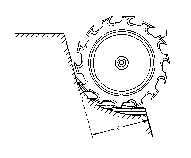
Fig. 1 - is a perspective view showing a disk-shaped
milling tool using the drop cut.
Figs. 2 and 3 - show a disk-shaped milling tool complete
with its drive, in various views.
Detailed Description of the Preferred l~~mbodiment
Figure 1 shows in schematic form a disk-shaped milling tool, capable
of working hard rock using either the parallel cut or drop cut.
This way of mining is particularly advantageous and practical when
working with layered or compact rock, arc no large fragments are torn
out at the cutting end, which is not the case when the terrace cut
is used. Furthermore, the material to be conveyed is more finely
structured, since the greatest thickness of chip is encountered at
the start of whichever cut is used.
Figs. 2 and 3 show a disk-shaped milling tool complete with its
drive, seen in different views. The milling tool (1) consists of
a supporting element (2) and an external tool support (3), which
combine to form the supporting element of the milling tool (1) as
the welded construction (4). A ring support (5) is radially welded
to tool support (3) as an annular disk-shaped component (face
surface) and projects into the cutting elements, of which there are
32 in this model, and which are actually U-shaped (6) with welded-on
teeth (7). At their free ends, the cutting elements (6) project
ag/via

2112813
-5-
into a further ring support, also disk-shaped, (8) (face surface),
axially spaced from the first ring support. The ring supports (5)
(8) and the cutting elements (6) are formed as one piece so as to
create the supporting component (3). T'he drive (9) for the milling
tool (1) lies on the central axis (10) of the milling tool and is
designed to provide a theoretical conveying capacity when installed
of m3/h per 0.35 kW. Additional teeth (11,12), referred to as side
cutters, are located in the region of face surfaces (5,8).
Bridges (13), running more or less horizontally, are provided as
bracing for the ring supports (5,8) which form the face surfaces.
Depending on the dimensions of the unit, these bridges (13) could
be replaced by a box-shaped type of construction. Particle
deflectors (14) are arranged laterally with respect to the cutting
elements (6) in order to repel the larger fragments of milled
material.
The flexible fashioning of the cutting edge backs in the shape of
pouches (15) is illustrated briefly. The cutting elements (6) are
close set, with only a relatively small separation (a) as viewed in
the direction of the periphery, in order that the milled material
can be extracted in a relatively finely structured form. As
mentioned above, the number of cutting elements (6) amounts to 32,
whereby each of these elements (6) is provided with four teeth (7).
a9/Vie

Representative Drawing
A single figure which represents the drawing illustrating the invention.
Administrative Status

2024-08-01:As part of the Next Generation Patents (NGP) transition, the Canadian Patents Database (CPD) now contains a more detailed Event History, which replicates the Event Log of our new back-office solution.

Please note that "Inactive:" events refers to events no longer in use in our new back-office solution.

For a clearer understanding of the status of the application/patent presented on this page, the site Disclaimer , as well as the definitions for Patent , Event History , Maintenance Fee  and Payment History  should be consulted.

Event History

Description Date
Time Limit for Reversal Expired 2007-06-26
Letter Sent 2006-06-23
Inactive: Cover page published 2001-09-05
Inactive: Acknowledgment of s.8 Act correction 2000-07-21
Inactive: Cover page published 2000-07-21
Inactive: Prior art correction 2000-07-21
Inactive: S.8 Act correction requested 2000-07-13
Grant by Issuance 2000-06-13
Inactive: Cover page published 2000-06-12
Inactive: Status info is complete as of Log entry date 2000-03-27
Inactive: Application prosecuted on TS as of Log entry date 2000-03-27
Inactive: Final fee received 2000-03-13
Pre-grant 2000-03-13
Letter Sent 2000-01-11
Notice of Allowance is Issued 2000-01-11
Inactive: Approved for allowance (AFA) 1999-12-08
Inactive: Multiple transfers 1999-02-17
All Requirements for Examination Determined Compliant 1994-06-07
Request for Examination Requirements Determined Compliant 1994-06-07
Application Published (Open to Public Inspection) 1993-01-21

Abandonment History

There is no abandonment history.

Maintenance Fee

The last payment was received on 1999-05-27

Note : If the full payment has not been received on or before the date indicated, a further fee may be required which may be one of the following

  • the reinstatement fee;
  • the late payment fee; or
  • additional fee to reverse deemed expiry.

Please refer to the CIPO Patent Fees web page to see all current fee amounts.

Fee History

Fee Type Anniversary Year Due Date Paid Date
MF (application, 5th anniv.) - standard 05 1997-06-23 1997-05-26
MF (application, 6th anniv.) - standard 06 1998-06-23 1998-05-21
Registration of a document 1999-02-17
MF (application, 7th anniv.) - standard 07 1999-06-23 1999-05-27
Final fee - standard 2000-03-13
MF (patent, 8th anniv.) - standard 2000-06-23 2000-06-13
MF (patent, 9th anniv.) - standard 2001-06-25 2001-05-28
MF (patent, 10th anniv.) - standard 2002-06-24 2002-05-17
MF (patent, 11th anniv.) - standard 2003-06-23 2003-05-20
MF (patent, 12th anniv.) - standard 2004-06-23 2004-05-26
MF (patent, 13th anniv.) - standard 2005-06-23 2005-05-27
Owners on Record

Note: Records showing the ownership history in alphabetical order.

Current Owners on Record
KRUPP FORDERTECHNIK GMBH
Past Owners on Record
JOACHIM METT
WOLFGANG FLEISCHHAKER
Past Owners that do not appear in the "Owners on Record" listing will appear in other documentation within the application.
Documents

To view selected files, please enter reCAPTCHA code :


To view images, click a link in the Document Description column. To download the documents, select one or more checkboxes in the first column and then click the "Download Selected in PDF format (Zip Archive)" or the "Download Selected as Single PDF" button.

List of published and non-published patent-specific documents on the CPD .

If you have any difficulty accessing content, you can call the Client Service Centre at 1-866-997-1936 or send them an e-mail at CIPO Client Service Centre.


Document
Description 
Date
(yyyy-mm-dd) 
Number of pages   Size of Image (KB) 
Cover Page 2000-05-25 1 41
Representative drawing 1999-05-10 1 10
Representative drawing 2000-05-25 1 9
Description 1995-05-13 6 207
Description 1999-12-01 5 193
Drawings 1999-12-01 1 19
Claims 1999-12-01 1 29
Cover Page 1995-05-13 1 25
Claims 1995-05-13 1 24
Abstract 1995-05-13 1 18
Drawings 1995-05-13 1 36
Cover Page 2000-07-20 1 40
Cover Page 2000-07-19 2 64
Commissioner's Notice - Application Found Allowable 2000-01-11 1 166
Maintenance Fee Notice 2006-08-21 1 173
Correspondence 2000-03-13 2 55
Fees 2000-06-13 1 28
Correspondence 2000-07-13 2 78
Fees 1996-05-22 1 69
Fees 1994-07-29 1 47
Fees 1995-05-24 1 66
International preliminary examination report 1994-01-04 30 1,073
Examiner Requisition 1996-12-20 2 83
Prosecution correspondence 1997-06-18 3 92
Courtesy - Office Letter 1994-10-19 1 38
Prosecution correspondence 1994-06-07 1 36