Note: Descriptions are shown in the official language in which they were submitted.
2113208
Title: GAS BURNER
BACKGROUND OF THE INVENTION
1. Field of the Invention
This invention relates to a gas burner, more
particularly to a gas burner which has several length-
adjustable gas delivery pipes.
2. Description of the Related Art
A conventional gas burner includes an inner gas
outlet member, an outer gas outlet member, a gas supply
pipe unit equipped with two nozzles, an inner gas
delivery pipe interposed between the gas supply pipe
unit and the inner gas outlet member, and an outer gas
delivery pipe interposed between the gas supply pipe
unit and the outer gas outlet member. In order to
achieve effective mixture of combustible gas and enough
air in the inner and outer gas delivery pipes, it is
necessary for the inner and outer gas delivery pipes to
have a ratio of length to diameter of about 6 to 10.
The conventional gas burner suffers from the following
disadvantages:
(1) Because only one outer gas delivery pipe is
provided between the gas supply pipe unit and the outer
gas outlet member of the conventional gas burner, the
outer gas delivery pipe is relatively long, resulting
in increased height of the burner head.
(2) Air can access the spaces between the gas supply
pipe unit and the inner gas delivery pipe and between
2113208
the gas supply pipe unit and the outer gas delivery
pipe through a relatively long air passage in the
conventional gas burner, so the amount of air mixed
with the combustible gas coming from the gas supply
pipe unit is insufficient to gain a satisfactory
burning effect.
(3) The positions of the nozzles in the gas burner
cause difficulties in adjusting or replacing the
nozzles. In particular, the majority of the gas burner
must be disassembled before adjusting or replacing the
nozzles.
(4) The amount of air needed to mix with different
types of gas in the gas burner falls into three
different ranges. Because the distances between the
nozzles and the outer gas delivery pipes and between
the nozzles and the inner gas delivery pipe are fixed,
the conventional gas burner can be used with only one
of liquefied petroleum gas, natural gas, or city gas.
SUMMARY OF THE INVENTION
An object of this invention is to provide a highly
efficient gas burner with several gas delivery pipes
which are shorter than those of prior art gas burners.
Another object of this invention is to provide a
gas burner in which the distances between the gas
supply pipe unit and the inner gas delivery pipe and
between the gas supply pipe unit and the outer gas
delivery pipe are adjustable so as to use with a gas
2113208
selected from liquefied petroleum gas, natural gas, or
city gas.
Still another object of this invention is to
provide a gas burner with replaceable nozzles so as to
use with a gas selected from liquefied petroleum gas,
natural gas, or city gas.
According to this invention, a gas burner includes
an inner gas outlet member, an inner gas delivery pipe
disposed under the inner gas outlet member, an annular
outer gas outlet member, several outer gas delivery
pipes disposed under the outer gas outlet member, a
head seat disposed under the inner and outer gas
delivery pipes and including a first gas supply pipe
and a second gas supply pipe, several first nozzles
installed on the first gas supply pipe, a second nozzle
installed on the second gas supply pipe, and an air
inlet unit formed in the outer surface of the gas
burner between the outer gas outlet member and the head
seat.
The inner gas outlet member has a plurality of
inner gas outlets formed therein. The inner gas
delivery pipe has an inlet, an outlet communicated with
the inner gas outlets, two interconnected tubular
sections movable relative to each other so as to adjust
the length of the inner gas delivery pipe, and a
locking unit for releasably interlocking the tubular
sections. The outer gas outlet member has a plurality
- 2113208
of outer gas outlet formed therein. Each of the outer
gas delivery pipes has an inlet, an outlet communicated
with the outer gas outlets, two interconnected tubular
sections movable relative to each other so as to adjust
the length of the outer gas delivery pipe, and a
locking unit for releasably interlocking the tubular
sections of the outer gas delivery pipe. A head seat
includes a first gas supply pipe accepting the
combustible gas from a gas supply source, and a second
gas supply pipe connected securely to the first gas
supply pipe so as to accept the combustible gas from a
gas supply source. The first nozzles are mounted
removably on the first gas supply pipe and are spaced
apart from the inlets of the outer gas delivery pipes
respectively so as to direct the combustible gas from
the first gas supply pipe to the inlets of the outer
gas delivery pipes. Each of the first nozzles is
associated with a corresponding one of the outer gas
delivery pipes to define a first air mixing space
therebetween. The second nozzle is mounted removably
on the second gas supply pipe and is spaced apart from
the inlet of the inner gas delivery pipe so as to
direct the combustible gas from the second gas supply
pipe to the inlet of the inner gas delivery pipe. The
second nozzle and the inner gas delivery pipe together
define a second air mixing space therebetween. The air
inlet unit is communicated with the first and second
- 2113208
air mixing spaces. The combustible gas coming from the
first and second nozzles is mixed with air in the first
and second air mixing spaces, and flows out of the
inner and outer gas outlet members through the inner
and outer gas delivery pipes.
BRIEF DESCRIPTION OF THE DRAWINGS
Other features and advantages of this invention
will become apparent in the following detailed
description of the preferred embodiments of this
invention, with reference to the accompanying drawings,
in which:
Fig. 1 is an exploded view showing the first
embodiment of a gas burner according to this invention;
Fig. 2 is a sectional view showing the first
embodiment of this invention;
Fig. 3 is a schematic view illustrating the use of
the first embodiment of this invention; and
Fig. 4 is an exploded view showing the secon'd
embodiment of the gas burner of this invention.
DETAILED DESCRIPTION OF THE PREFERRED EMBODIMENTS
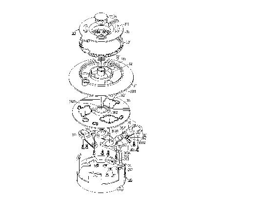
Referring to Figs. 1 and 2, the first embodiment
of the gas burner of this invention includes a molded
head seat (20) and a burner head unit (30).
The head seat (20) includes a gas supply pipe unit
consisting of a fixed first gas supply pipe (21) and a
fixed second gas supply pipe (22) which are connected
to a gas supply source via connecting pipes (23, 231).
- 2113208
The first gas supply pipe (21) has three projections
(24) each of which has an outlet (241). The second gas
supply pipe (21) has a projection (24) which has an
outlet (241). Three inclined first nozzles (25) have
externally threaded ends (251) engaged within the
threaded holes (242) of the projections (24) of the
first gas supply pipe (21). An inclined second nozzle
(25) is mounted removably on the second gas supply pipe
(22) in the same manner as the first nozzles (25).
The burner head unit (30) includes an annular
outer support (31) with three circular soup holes (311)
formed therethrough, and an annular inner support (31)
connected securely to the outer support (31). The
inner support (32) has a fixed vertical pipe (321) at
the center thereof. An annular outer gas outlet member
(33) is placed on a support ring (331) which is
positioned on the outer support (31). Much space is
left between the outer gas outlet member (33) and the
support ring (331) so as to form an air inlet unit
(332). A plurality of outer gas outlets (333) are
formed through the outer gas outlet member (33) in
communication with the air inlet unit (332) through
which air can enter the gas burner. An inner gas
outlet member (34) is placed on the vertical pipe (321)
of the inner support (32) and is surrounded by the
outer gas outlet member (33). A soup tray (35) is
disposed between the head seat (20) and the outer
- 2113208
support (31) and between the head seat (20) and the
inner support (32), and includes three holes (351)
formed therethrough, and a securing projection (352)
with a central hole (3521) formed therethrough. Each
of the holes (351) is defined by an annular upward
flange (3511) which prevents the soup falling from a
pot (4) from flowing out of the tray (35). Three
inclined outer gas delivery pipes (36) have upper ends
secured to the outer support (31) in such a manner that
the interiors of the outer gas delivery pipes (36) are
respectively communicated with the soup holes (311).
An inclined inner gas delivery pipe (37) is secured to
the soup tray (35) in such a manner that the interior
of the inner gas delivery pipe (37) is communicated
with the central hole (3521) of the soup tray (35).
Each of the outer gas delivery pipes (36) has a
fastening end (361) secured to the outer support (31)
in such a manner that an air-tight seal is established
therebetween, a fixed tubular section (362) connected
securely to the fastening end (361), and a movable
tubular section (363) having an upper end engaged
within the increased-inner-diameter lower end (3621) of
the fixed tubular section (362). The fixed tubular
section (362) has a radial projection (3632) protruding
outward from the peripheral wall thereof, through which
a threaded hole (3634) is formed so that the movable
tubular section (363) can be locked on the fixed
- 2113208
tubular section (362) by means of a lock bolt (3635),
thereby adjusting the length of the outer gas delivery
pipe (36). The radial projection (3632), the threaded
hole (3634), and the lock bolt (3635) together
constitute a locking unit for releasably locking the
movable tubular section (363) on the fixed tubular
section (362). Similarly, the inner gas delivery pipe
(37) includes a fastening end (371), a fixed tubular
section (372) with an increased-inner-diameter lower
end (3721), a movable tubular section (373), a radial
projection (3732) with a threaded hole (3734), and a
lock bolt (3735). Each of the outer and inner gas
delivery pipes (36, 37) has an inlet at the lower end
thereof, and an outlet at the upper end. The inlet of
each of the outer and inner gas delivery pipes (36, 37)
is spaced apart from a corresponding one of the nozzles
(25) at a certain distance which is determined
according to the type of the combustible gas supplied
from the first and second gas supply pipes (21, 22). A
first air mixing space is defined between the inlet of
each of the outer gas delivery pipes (36) and the
corresponding nozzle (25). A second air mixing space
is defined between the inlet of the inner gas delivery
pipe (37) and the corresponding nozzle (25). As shown
in Fig. 2, the first and second air mixing spaces are
communicated with the air inlet unit (332).
2113208
When the type of the combustible gas is changed,
the burner head unit ( 30) iS removed from the head seat
(20) so as to replace the nozzles (25) and to adjust
the lengths of the outer and inner gas delivery pipes
5(36, 37), thereby adjusting the distances between the
the gas supply pipe unit and the gas delivery pipes
(36, 37).
In comparison with the prior art, because the
number of the outer gas delivery pipes (36) is
10increased, the amount of air needed to mix with the
combustible gas in each of the pipes ( 36) and between
the inlet of each of the pipes ( 36) and the
corresponding nozzle ( 25) is much reduced.
Accordingly, in a case where the ratio of length to
15diameter of the outer and inner gas delivery pipes (36,
37) is about 6 to 10, the lengths of the outer and
inner gas delivery pipes (36, 37) are much reduced so
that the height of the gas burner of this invention is
reduced and that the distances from the air inlet unit
20(332) to the inlets of the outer and inner gas delivery
pipes ( 36, 37) are reduced, thereby achieving quick
supplement of air into the gas burner.
Fig. 4 shows the second embodiment of the gas
burner of this invention. Unlike the previous
25embodiment, the burner head unit (30' ) includes three
vertical outer gas delivery pipes (36' ) and a vertical
inner gas delivery pipe ( 37 ' ) which are respectively
- 2113208
aligned with the vertical nozzles (25') of the head
seat (20').
With this invention thus explained, it is apparent
that numerous modifications and variations can be made
without departing from the scope and spirit of this
invention. It is therefore intended that this
invention be limited only as indicated in the appended
claims.
-- 10 --