Language selection

Search

Patent 2113295 Summary

Third-party information liability

Some of the information on this Web page has been provided by external sources. The Government of Canada is not responsible for the accuracy, reliability or currency of the information supplied by external sources. Users wishing to rely upon this information should consult directly with the source of the information. Content provided by external sources is not subject to official languages, privacy and accessibility requirements.

Claims and Abstract availability

Any discrepancies in the text and image of the Claims and Abstract are due to differing posting times. Text of the Claims and Abstract are posted:

  • At the time the application is open to public inspection;
  • At the time of issue of the patent (grant).
(12) Patent Application: (11) CA 2113295
(54) English Title: LENS MARKINGS VIEWER
(54) French Title: DISPOSITIF D'INSPECTION DE LENTILLES
Status: Deemed Abandoned and Beyond the Period of Reinstatement - Pending Response to Notice of Disregarded Communication
Bibliographic Data
Abstracts

English Abstract


In the process for producing ophtalmic progressive lenses, it is common practice to
inspect lenses using a lamp and the effects of ambiant light refraction to detect surface
imperfections as well as for retreiving manufacturers markings. Such markings
containing key process information are mandatory for further finishing and cutting
processes of the ophtalmic progressive lenses. In this invention, light is generated by a
coherent light source at a given wavelenght that may range between 620 and 670
nanometer and collimated prior to being difused over the surface of the lens under
inspection. The lens under inspection may be moved at an angle .beta. in the path of the
difused light to enhance light refraction occuring onto the markings and other surface
imperfections. The light is thus refracted to a projection surface for viewing by the
human eye (operator) to clearly examine the markings as well as the surface
imperfections before and after coatings and other treatments. In this invention, the
optical aparatus is contained into an instrument which encompasses all of the
necessary mechanism to enable the examination of most types of ophtalmic lenses.The angle .beta. may be modified by the operator to adapt to different lenses curvature.
This is achieved by manipulation of a controller arm until optimum viewing is achieved.
The light source intensity as well as focus may be adjusted during the process of
examining lenses.


Claims

Note: Claims are shown in the official language in which they were submitted.

The embodiments of the invention in which an exclusive property or privilege is
claimed are defined as follows;
1. An instrument for the examination of markings used in the fabrication of ophtalmic
lenses comprising: an optical apparatus for generating said refraction of light to
produce said projection of markings.
2. The instrument of claim 1, wherein said optical apparatus is used for generating
said refraction of light to produce said projection of surface imperfections of ophtalmic
lenses.
3. An optical apparatus for generating said refraction of light for examining ophtalmic
lenses comprising: a light source, a collimator and a diffuser for examining said
markings and said surface imperfections.
4. The instrument of claim 1, wherein said optical apparatus for generating saidrefraction of light comprises: a two axis controllable inclination plateform to create said
refraction angle .beta..
5. A method of detecting ophtalmic lens markings and surface imperfections
comprising: an optical apparatus for generating said refraction of light to produce said
projection onto the said projection area.
6. The instrument of claim 1, wherein said optical apparatus comprises: a light source
and adjustment of same used to enhance said examination of markings and said
surface imperfections.
7. The instrument of claim 1, wherein said optical apparatus comprises: a focus
adjustment used to enhance said examination of markings and said surface
imperfections.

Description

Note: Descriptions are shown in the official language in which they were submitted.


- 2113295
SPECIFICATION
-
This invention relates to an instnument containing an optical aparatus and mechanisms
for inspecting ophtalmic progressive lenses for the viewing of markings and
imperfections.
It is common in processes for inspecting lenses or for retreiving markings on ophtalmic
lenses to use such optical aparatus as lamps or ambiant light to create superficial
refraction in order to view engraved markings on progressive lenses or to inspect
surface quality of semi-finished or finished ophtalmic lenses using same. Such
methods are, however, inefficient because of the lens manipulations that the method
require as well as improper retreival of markings often due to insuffi~ient lighting and
incorrect refraction angles. Manually applied processes cause instability and operator
fatigue which are also causes of human error as well as potential permanent
degradation of the operators vision if such individual is assign this duty for long periods
of time.
I have found that these disadvantages may be overcome by providing an integratedinstrument incorporating sufficient lighting, reflection angle selection capability and
magnified projection capability. Such an aparatus reduces manipulation to the simple
placing of the lenses onto the examination surface area. Controls provided for the
adjustements of light intensity and selection of refraction angle provide for accuracy
and greater stability while examining the lenses. The magnified projection of refracted
light offers reduced human eye fatigue and provide better efficiency of the process.
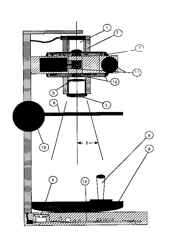
In the drawings which illustrate embodiments of the invention, Figure 1 is a side view of
the optical assemblies and Figure 2 is a front view of the instrument with all controls.
The instrument illustrated comprises a coherent light source 1 which is mounted into
an optical body 2 toward a collimator 3 and emits light of intensity one to fourmiliwatts and wavelenght 620 to 670 nanometer when activated by the power supply4. An HeNe lamp may be used as a coherent light source as shown in figure 1 but a
laser diode emiting within the same wavelenght may be used if desired. Light emitted
through the collimator 3 is directed onto a difuser 5 which provides for a three inch
diameter illumination of the examination surface area 6. The examination surface area
6 is mounted onto a controlable inclination plateform 7 which may be inclined in both
X and Y axis within a range of + and - 30 degrees using the control lever 8 to provide
for the refraction angle 13. The difused light refracted onto the examination surface
area 6 is then projected onto a projection area 9. The imperfections and markings
which refract light at different angles are seen on the projection area 9 as darker
patterns that are very clearly visible. The coherent light source 1 intensity may be
adjusted using the intensity control 10 to overcome the effect of ambiant light. Focus

~ 2113295
adjustment 18 may be used to accentuate the sharpness of the projected markings as
well as surface imperfections.
The adjustment of the refraction angle B is achieved by control motors 11 located to
provide inclination in both X and Y axis through a gear mechanism 12. The degree of
inclination and its direction within the span of + and - 30 degrees in both axis is
obtained by the activation of the control lever 8 in the direction and axis desired. The
operation of the control lever 8 is similar to that of a joystick and is directly inputed to
the electronic circuit 13. The electronic circuit 13 is used to provide the control motors
12 with the required voltage as inputed by means of the control lever.
An additional function of the electronic circuit 13 is to control the intensity of the
coherent light source 1 by supplying the necessary voltage as selected by the
operator using the intensity switch 14. Selection of light intensity level as displayed on
level meter 16 is achieved by pressing the light intensity swicth 14. Each time the light
intensity switch 14 is pressed, the light source 1 intensity will increment by a factor of 1
on a scale of 0 to 9. The electronic circuit 13 will output to the coherent light source 1
a corresponding power value. The power supply 4 contains a voltage transformer
which reduces standard 110 AC voltage required to supply the instrument to 5 volts DC
required by the electronic circuit 13. Power may be interupted using switch 17.
The electronic circuit 13 contains a self test routine that is initiated on power up of the
instrument. The condition of the instrument upon self test is shown on the front panel
using " fault and function " LEDs (light emiting diode).
As will be appreciated, an instrument as illustrated by figure 1 and 2 and as described
in the specification above has numerous applications throughout the industry of optics
for the purpose of inspecting and/or examining lenses at various stages of the making.
Exemples of such applications are for inspection of surface quality after treatments and
coatings, inspection of semi-finished and finished lenses used for telescopes,
binoculars and other similar products.
Those skilled in the art will recognise that the embodiments disclosed herein are
unique in nature and that various changes can be made therein without departing from
the scope and sperit of the invention. In this regard, and as was previously mentioned,
the invention is readily embodied with various light source configurations which will
provide similar results. Other mecanisms may be applied for producing the necessary
refraction angle and magnification all aiming at the same principle described herein.
--3-

Representative Drawing
A single figure which represents the drawing illustrating the invention.
Administrative Status

2024-08-01:As part of the Next Generation Patents (NGP) transition, the Canadian Patents Database (CPD) now contains a more detailed Event History, which replicates the Event Log of our new back-office solution.

Please note that "Inactive:" events refers to events no longer in use in our new back-office solution.

For a clearer understanding of the status of the application/patent presented on this page, the site Disclaimer , as well as the definitions for Patent , Event History , Maintenance Fee  and Payment History  should be consulted.

Event History

Description Date
Inactive: IPC from MCD 2006-03-11
Time Limit for Reversal Expired 1996-07-13
Application Not Reinstated by Deadline 1996-07-13
Inactive: Adhoc Request Documented 1996-01-12
Deemed Abandoned - Failure to Respond to Maintenance Fee Notice 1996-01-12
Application Published (Open to Public Inspection) 1995-07-13
All Requirements for Examination Determined Compliant 1994-03-24
Request for Examination Requirements Determined Compliant 1994-03-24

Abandonment History

Abandonment Date Reason Reinstatement Date
1996-01-12
Owners on Record

Note: Records showing the ownership history in alphabetical order.

Current Owners on Record
ROGER DORE
Past Owners on Record
None
Past Owners that do not appear in the "Owners on Record" listing will appear in other documentation within the application.
Documents

To view selected files, please enter reCAPTCHA code :


To view images, click a link in the Document Description column. To download the documents, select one or more checkboxes in the first column and then click the "Download Selected in PDF format (Zip Archive)" or the "Download Selected as Single PDF" button.

List of published and non-published patent-specific documents on the CPD .

If you have any difficulty accessing content, you can call the Client Service Centre at 1-866-997-1936 or send them an e-mail at CIPO Client Service Centre.


Document
Description 
Date
(yyyy-mm-dd) 
Number of pages   Size of Image (KB) 
Cover Page 1995-09-01 1 14
Abstract 1995-07-13 1 39
Claims 1995-07-13 1 36
Description 1995-07-13 2 119
Drawings 1995-07-13 2 88
Representative drawing 1998-05-12 1 52
Courtesy - Office Letter 1994-09-12 1 41
Prosecution correspondence 1994-03-24 1 26