Language selection

Search

Patent 2113777 Summary

Third-party information liability

Some of the information on this Web page has been provided by external sources. The Government of Canada is not responsible for the accuracy, reliability or currency of the information supplied by external sources. Users wishing to rely upon this information should consult directly with the source of the information. Content provided by external sources is not subject to official languages, privacy and accessibility requirements.

Claims and Abstract availability

Any discrepancies in the text and image of the Claims and Abstract are due to differing posting times. Text of the Claims and Abstract are posted:

  • At the time the application is open to public inspection;
  • At the time of issue of the patent (grant).
(12) Patent Application: (11) CA 2113777
(54) English Title: BRAKING DEVICE PARTICULARLY FOR SKATES WITH ALIGNED WHEELS
(54) French Title: DISPOSITIF DE FREINAGE, SURTOUT POUR PATINS A ROUES ALIGNEES
Status: Deemed Abandoned and Beyond the Period of Reinstatement - Pending Response to Notice of Disregarded Communication
Bibliographic Data
(51) International Patent Classification (IPC):
  • A63C 17/14 (2006.01)
  • A63C 17/06 (2006.01)
(72) Inventors :
  • CONTE, GINO (Italy)
(73) Owners :
  • ROCES S.R.L.
(71) Applicants :
  • ROCES S.R.L. (Italy)
(74) Agent: ROBIC AGENCE PI S.E.C./ROBIC IP AGENCY LP
(74) Associate agent:
(45) Issued:
(22) Filed Date: 1994-01-19
(41) Open to Public Inspection: 1994-07-20
Availability of licence: N/A
Dedicated to the Public: N/A
(25) Language of filing: English

Patent Cooperation Treaty (PCT): No

(30) Application Priority Data:
Application No. Country/Territory Date
TV93A000005 (Italy) 1993-01-19

Abstracts

English Abstract


ABSTRACT
A braking device, particularly for skates having a
frame to which a plurality of mutually aligned wheels is
pivoted. The device is constituted by an element which is
pivoted to the frame in contrast with a spring and interacts
with the ground at a first end upon a backward rotation of
the skate. The device comprises a second end which interacts
with the lateral surfaces of one of the wheels, allowing to
preserve them from wear.
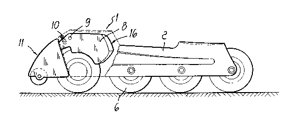
(Ref. Fig. 1)


Claims

Note: Claims are shown in the official language in which they were submitted.

CLAIMS
1. Braking device, particularly for skates comprising a
frame having a plurality of mutually aligned wheels
pivoted therein, wherein it comprises an
element pivoted to said frame in contrast with an
elastically deformable element and interacts with the
ground at a first end, upon a backward rotation of said
skate, and with the lateral surfaces of one of said wheels
at a second end.
2. Device according to claim 1, wherein said frame
is a U-shaped and has first wings which are directed toward
the ground and to which said plurality of mutually aligned
wheels are pivoted, said element having a central body which
is associated, so that it can oscillate, between said first
wings of said frame by means of a first pivot.
3. Device according to claim 2, wherein said central
body is partially arranged within said frame and can
oscillate in contrast with said elastically deformable
element.
4. Device according to claim 3, wherein said central
body has a first end which is external to said frame and is
formed by a shell, a roller being freely pivoted, by means
of a second pivot, below second wings of said shell and
interacting with the ground upon a backward rotation
imparted to the skate.
5. Device according to claim 4, wherein said
elastically deformable element is constituted by a pre-
compressed spring which is interposed between said central
body and said frame so that said second wings of said shell
remain in abutment against said first wings of said frame in
order to keep said roller raised from the ground during
normal sports practice.

6. Device according to claim 5, wherein
said central body has a second end which is arranged inside
said frame and surmounts one of said wheels in the condition
for normal sports practice, the surface of said second end
which faces said wheel having a concave shape so as to form
two inclined planes which interact with the lateral
surfaces, or with the surfaces adjacent to the rolling
surface, of said underlying wheel during braking, the
braking action being obtained upon a backward rotation of
said skate that makes said roller touch the ground.
7. Device according to claim 6, wherein said
elastically deformable element is constituted by a spring
which is interposed between said frame and said second end
so as to keep said inclined planes raised with respect to
said lateral surfaces, of said underlying wheel during
normal sports practice.

Description

Note: Descriptions are shown in the official language in which they were submitted.


21 ~ 3777
BACKGR~)11Nr) OF THE INVENrl'l()N
1. Field of the invent:ic)n
li'he F)resent invention relates to a brakiTl~l df~?ViC~-!
E)articularly fc)r 5kates wi t.h aligned wheelc~ .
5 2. Descriptioll of tlle Prior Art
Bringing tlle ~?kate tc~ a f1~ll c?tc)F) durillg sE)c)rt.C.?
practice is currently a prob1e1n for the skater; ill
cc)nvent:ional .~kat.es ~ a brake Collc?ti t~l~ t~et3 bv a k)l ock c)f
plastic material i~? in fact associated to the rear o~ the
10 wheel suElporting frame, ant3 sai~l blc)ck is ~na~3f? t.o irlt,f.?ract.
wit11 the groun-l bv rotatillg the .~-Jkat e bakward ~
llc)wevt?l, thi~ oE)eration is lJazr~r~3ol~ ,? in~'e i t. can
callse the skater to lc)~4e hiS balar)ce. w-il~h dangero~
c~c~ll~?~?~llJ~ ec.? . ~ tl~f?l Illc)r e, t.h~ c,c~l~ wears ~ .
15 corlsiderablv anc3 nlllst be replacecd verv frequentlv~
Co]lltiorl~: are alsc) kl~owll whicll provi(if.~ fc).r t.lJ
inl-er.3ct.-ic)1l o~ a hralze direc1:lv c)rl ~.he rollinc1 sllrt.~ce of
t.ll~? wl~?el: t.llf~? C~C)~ ?(~cllf?l~t. (1r.lwl:-c3~ )f c~ r c~ ? t.ll~? ll~!f.?~3 ~ ~)
-c el)l rlce t he wl1ee l f re~uen ~ l v . ~;
2() ~?,IJMMARS- OF ~HE INVE:N'r~)N
'I'1-~e aim of the prese1lt ir~ver1tio11 i.s to s-~lve? th~!
de.s?cril~ed draw3-)acks bv ~)rovidiJlg a skat.f? wllic1l al 1c~ws ~l]f~!
skater to ~4top it or rec3~1ce it5 5rleed while prf?sf.?rvillcl t.~lf?
W 11 f~! ~? 1 f r C)lll W f ? cJ 1 a 11~3 a :1 1 ( ) w i ~1 C1 t. ~ . li a t. f.! r t. c) E~ .? r f o :~ 111 t. i1 C?
2ri mallel~ver ill 5a~ety.
A ~llrther ol:)ject, if; l:o prc)vide a ~:kr3te wil.ll aligned
whee]s which a;llc)ws t.he skat.er t.o acllieve l:)ett.er 3')1''r3kiJ1~3
cc)ntrol .
Another in~pc)rtallt ol:,ject is to prc)vide a r,kclte whic
~0 ha a i~iml)le .~:t.ruct.llre an~l i;: ~.?aSV t.c) illdl3C trial i7.ce.
Another object i~: to prc)vide a braking devic~e w1-1ich is,
~?~ i C'31)1 t?, ~lf e ill 1~ ? aIl(~ Jlc~ v~?r~ ~ ow 311c3l~l3i c~ Jr i~

21~ 37 i7
co~ts which allc,w its wide.~pread di.ffusioll and appl1catic)n
even t.o cnnvel]ti{)lJal skates.
This aim tllese objects and otllers which will. becc)nle
ap~arent froTn the fc)llnwing de~criptic)ll are achieved by a
braking devices a~ claimed in the appendec3 claims.
BR~EF DESRIPTION 03~ THE DRAWINC.S
Other c)bjects will become apparent during the following
descri~tioll which DIUSt. he cc-ncidered t.nget.her wit.h t.he
accompanying drawing~ which illllstrate by wav of nl-)n-
n limit:at.ive exallly)le, a -~)art.ic~lar emhodill~elll., :in wl~
Fiyure I .is a partia:lly sectiorlaL sic3e view o~ a
~30rt.ic~n nf a skat.e wherein t.he device is shc~wll in t.he
inactive condition
Figure 2 is an exploded partial view o~ solne c)f the
1S cc)mF)mlents c-f thc device
Figure 3 is a cross sectic)n view of the device taken
at the element as~c)ciat.ed with the frallle irl t.he l.)ra~;:ing
conditic)ns.
DESCRIPT~ON OF A PREFE~RED
~() EM~)n~ENT O~ ~HE ~NV~NTJ~)N
With reference l:o the above r:i.gures and cc,llsi(3eri.lly
t:hat. thev exemE~lify a F)articll]ar elllbc)c3iment. and are iJl
variable scale and that identical. (~r e(~l3ivalel-lt ~)art~s
cc)rrespc)n(3 to in(3ivi(31~al reference nllmeralc. in said ligl~res
the numeral 1 designate~ t:h~ hrakiny device ~arl.icl33.ar1v
fc-r skate~ cc)mE)rising a ll-sha~)ed frame 2 Wit.]1 first. wingC~ ~
and 4 directed toward the grnl]nd 5; a ~lurality c)f mutuallv
aliyned wheels ~ i~ E~ivnte(l t.n t.he Willys.
The braking device i8 constitlited bv an element 7 which
3() i 8 cc)mpc)set3 of a central hndv ~ which is a.ssc)ciate(3 hetweel-
the ~irst wings 3 and 4 of the frame 2 8C) that it can
~wing al~c)llt. a first. ~iv,.)~. '3.
. . ~ . . , . ` ~ . ` , ~

i : `
21~ 3777
Thr? rcentral bodv 8 is partiallv accolllrllc)dat.ec'3 within the
frame 2 ancl can ~wil~g in c~()]ltra~:t. wit.h an el.3st.ical~v
de~ormal:le element, gucll as a ~pring 10.
The cent.ral bc)c'3v ~ has a first: end :~i, arrangecl o~lt~:icle
5 the ~rame 2, wllich i8 fc)rmed by a sh~?ll 12 having the sec~)nd
winy6 13a a~ 13'c). A roller 15 is freely ,c)ivc)t.ecl, hv Irlean~:
of ~ second pivot 1 4, below the secc,nd wingAs 1 3a and 1 3b and
interac?t.s wi th the grc)un~ )c)n a batakw.3rd rc)t-atic
imparted to the ~ska te .
1() 'rhe spring 1() can he int.erpc)sr?~l, in a pre--colllpre~ e~l
c~c)nditic)~ etween tl-le c.~ellt-.r~-31 b~.,dv ~ a~cl t;l,~3 rr;3me 2 !::m
that. thr? ~eCC)IlCi Will~: 13a arJ(l 1~ c)f l.he ~:hel~ 12 reJIlairl irJ
abutment against tlle fir~t. Will~S 3 an(l ~i of l:.hr.? ~rallle 2:
thi~: al.lc)w~: t.c) ker.?l-) t:l3e roller 1~ raiC C?~'3 frc)lD the C~rC~I]Il~J r~
durirlg r30rm~3]. spc)l-t~s practlce.
rl' he cen tral h o d v 8 h ~a~: a ':C?c~() n C~ e ncJ 1~ W h i ch iS
arrang~?d inside t.lle frame 2 and xurmr. I?nt;s c-lle ~.,f l-he wll~?r?l~s
~ :in the collclitic)Jl fc-r nc-rlllal spc)r-t.~: E~r.3ctic~-?. ']'lle ~:ecr
end 16 also has a ~:urface l7 Wl-licll f:aCr-?C; t;he Wlleel 6 arld }la~'~
2 0 a cc))lca v ~? ~ aFIr? 8c~ a 8 t.c) f c)rlll t; wo i 11 C' I i 11 r.?C3 F~ nc? C. I ~? ~ (3 1 .'~
which interac~t witll tlle lateral ~ rfac~es, c~r wit~ he
c;llrfaces ad jacellt. t:o the rc)llinc~ lrface, c)l- t.~le l~rl(lr?l ~vinrJ
wl1eel 6 during braki.ng.
I.~raking oc~ur~, u~c~c)n a backwar(l rotatiorl c~ I-Ie skl~.r?,
? I. r?rllli l'l r;?~ ~.iV t.l] e C~ 3 t. C!I", Wll i C`ll 111~ ~7 ~? ~ l r.? r ~ r.-~r :1 5 t. c
tlle arc)llrld 5.
This Lead.s tc~ the rc)~.ati.oll, a~c-ut. tl-le l~ir~:t r;)i.vc~t 9, {,1.
t.ll~? r~ el1lel-lt. 7, wllic~h fl~rt.~lel~ c~{)~ lr~?~ c) t.]le ~ ri~
makes the incline(3 plarles Id an(~ 1.9 interact witll tlle
3û lflteral s~lrLaces c)f the wheel.
The ~:princl lO can he int.erpc)~;e(3 }:letween tlle f:rame 2 arl(3
the secc)llcl el~ ;, sc~ a;. t.c~ ker?p tlle inc~ le~J ~:)l all~.?!; .J ~ al~l

` 2~3777
19 raised with respect to the lateral sur~aces c)r t;o t.he
surf~ce~; ad jacell~ tc) the rc)lling surface c~f the ul-lder~villg
wheel 6 during norma1 ..ports practice.
It hac. t.hlls beell c).~)served that t.he (iÇ?ViC'Ç.? has ~3chieved
5 the intended aim and object.s allowing the ~kater to stop
t.he ~:kate or redllce it.~: sE~eed while Ic)reserving t:he wheel
from wear since it is the roller which may also be rnade of
very ha:rd mat.erial that interacts Wit]l the grol~nd
Furthermore the fact that the rota.tic)n of the element 7
10 n~akes the i.nc~ ç?d planes jnterac t-. Wit.]l the lateral SUl faces
o~ the wheel a1so allows to sllift t]l~.? center of yravity of
t]~.? brakinc~ ac t.ic)rl bç-lc)w t.he fc,c,t: c,f t.he ~kat.el l-.h~
improving balance arld braking contrc)1 and -increasiny safetv.
rlatn~rallv the mat.ç?ria]s c>:~ which the eleoel]t~: c)f t.hç
15 qevice are made a~; wel1 as the dimerlsic)ns of the individua:L
comp~)llellt~; of t.he device .mav vary accc)r~ lg tc) the
reqllirements.
~0

Representative Drawing
A single figure which represents the drawing illustrating the invention.
Administrative Status

2024-08-01:As part of the Next Generation Patents (NGP) transition, the Canadian Patents Database (CPD) now contains a more detailed Event History, which replicates the Event Log of our new back-office solution.

Please note that "Inactive:" events refers to events no longer in use in our new back-office solution.

For a clearer understanding of the status of the application/patent presented on this page, the site Disclaimer , as well as the definitions for Patent , Event History , Maintenance Fee  and Payment History  should be consulted.

Event History

Description Date
Inactive: IPC from MCD 2006-03-11
Time Limit for Reversal Expired 2001-01-19
Application Not Reinstated by Deadline 2001-01-19
Deemed Abandoned - Failure to Respond to Maintenance Fee Notice 2000-01-19
Application Published (Open to Public Inspection) 1994-07-20

Abandonment History

Abandonment Date Reason Reinstatement Date
2000-01-19

Maintenance Fee

The last payment was received on 1999-01-15

Note : If the full payment has not been received on or before the date indicated, a further fee may be required which may be one of the following

  • the reinstatement fee;
  • the late payment fee; or
  • additional fee to reverse deemed expiry.

Patent fees are adjusted on the 1st of January every year. The amounts above are the current amounts if received by December 31 of the current year.
Please refer to the CIPO Patent Fees web page to see all current fee amounts.

Fee History

Fee Type Anniversary Year Due Date Paid Date
MF (application, 4th anniv.) - standard 04 1998-01-20 1998-01-07
MF (application, 5th anniv.) - standard 05 1999-01-19 1999-01-15
Owners on Record

Note: Records showing the ownership history in alphabetical order.

Current Owners on Record
ROCES S.R.L.
Past Owners on Record
GINO CONTE
Past Owners that do not appear in the "Owners on Record" listing will appear in other documentation within the application.
Documents

To view selected files, please enter reCAPTCHA code :


To view images, click a link in the Document Description column. To download the documents, select one or more checkboxes in the first column and then click the "Download Selected in PDF format (Zip Archive)" or the "Download Selected as Single PDF" button.

List of published and non-published patent-specific documents on the CPD .

If you have any difficulty accessing content, you can call the Client Service Centre at 1-866-997-1936 or send them an e-mail at CIPO Client Service Centre.


Document
Description 
Date
(yyyy-mm-dd) 
Number of pages   Size of Image (KB) 
Abstract 1994-07-19 1 33
Drawings 1994-07-19 1 68
Claims 1994-07-19 2 108
Descriptions 1994-07-19 4 208
Representative drawing 1998-08-20 1 12
Courtesy - Abandonment Letter (Maintenance Fee) 2000-02-15 1 185
Reminder - Request for Examination 2000-09-19 1 116
Fees 1998-01-06 1 38
Fees 1999-01-14 1 34
Fees 1997-01-15 1 30
Fees 1996-01-15 1 37
Courtesy - Office Letter 1994-04-11 1 17