Language selection

Search

Patent 2114130 Summary

Third-party information liability

Some of the information on this Web page has been provided by external sources. The Government of Canada is not responsible for the accuracy, reliability or currency of the information supplied by external sources. Users wishing to rely upon this information should consult directly with the source of the information. Content provided by external sources is not subject to official languages, privacy and accessibility requirements.

Claims and Abstract availability

Any discrepancies in the text and image of the Claims and Abstract are due to differing posting times. Text of the Claims and Abstract are posted:

  • At the time the application is open to public inspection;
  • At the time of issue of the patent (grant).
(12) Patent Application: (11) CA 2114130
(54) English Title: DEVICE FOR DEWATERING A PULP SUSPENSION
(54) French Title: DISPOSITIF DE DESHYDRATATION DE PATE EN SUSPENSION
Status: Deemed Abandoned and Beyond the Period of Reinstatement - Pending Response to Notice of Disregarded Communication
Bibliographic Data
(51) International Patent Classification (IPC):
  • D21F 01/02 (2006.01)
  • D21F 01/06 (2006.01)
  • D21F 01/76 (2006.01)
(72) Inventors :
  • LINDSTROM, ALF (Sweden)
(73) Owners :
  • SUNDS DEFIBRATOR INDUSTRIES AKTIEBOLAG
(71) Applicants :
  • SUNDS DEFIBRATOR INDUSTRIES AKTIEBOLAG (Sweden)
(74) Agent: SMART & BIGGAR LP
(74) Associate agent:
(45) Issued:
(86) PCT Filing Date: 1992-06-25
(87) Open to Public Inspection: 1993-03-04
Availability of licence: N/A
Dedicated to the Public: N/A
(25) Language of filing: English

Patent Cooperation Treaty (PCT): Yes
(86) PCT Filing Number: PCT/SE1992/000469
(87) International Publication Number: SE1992000469
(85) National Entry: 1994-01-24

(30) Application Priority Data:
Application No. Country/Territory Date
9102370-5 (Sweden) 1991-08-16

Abstracts

English Abstract

2114130 9304234 PCTABS00020
A device for dewatering a pulp suspension, comprising an
open-work movable surface (1) for forming and dewatering a pulp web. In
an inlet (2) for the pulp suspension to the movable surface (1), a
cylindric chamber (3) is located which encloses a rotatable
cylindric rotor (4), the shaft of which extends transverse to the
flow direction of the pulp. The rotor (4) is provided on its surface
with a plurality of crosswise arranged channels (7). The pulp is
forced to flow from an inlet (2) in the chamber (3) through the
channels (7) to an outlet (6) located on the opposite side of the
chamber (3).


Claims

Note: Claims are shown in the official language in which they were submitted.

WO 93/04234 PCT/SE92/00469
Claims
1. A device for dewatering a pulp suspension, compris-
ing an open-work movable surface (1) for forming and
dewatering a pulp web, and an inlet (2) for the pulp susp-
ension to the movable surface (1), c h a r a c t e r -
i z e d i n that in said pulp inlet (2) a rotatable
cylindric rotor (4) is located which with its shaft extends
transverse to the flow direction of the pulp and the
length of which substantially corresponds to the width
of the movable surface (1), that the rotor (4) on its
surface is provided with a plurality of cross-wise arr-
anged channels (7), and that the rotor (4) is enclosed
by a cylindric chamber (3), which has an inlet (5) and
an outlet (6) located substantially directly in front
of each other, so that the pulp is forced to flow through
the channels (7).
2. A device as defined in claim 1, c h a r a c t e r -
i z e d i n that the rotor (4) is arranged for slow
rotation, continuous or reversible.
3. A device as defined in claim 1 or 2, c h a r a c t -
e r i z e d i n that the channels (7) are arranged
helicoidally.
4. A device as defined in any one of the preceding
claims, c h a r a c t e r i z e d i n that the
channels (7) at their crossings form a substantially
right angle with one another.
5. A device as defined in any one of the preceding
claims, c h a r a c t e r i z e d i n that the rotor
(4) is rotatable at a speed of 1-20 rpm.

WO 93/04234 PCT/SE92/00469
6. A device as defined in any one of the preceding claims,
c h a r a c t e r i z e d i n that the diameter of the rotor (4)
is 50-100 mm.
7. A device as defined in any one of the preceding claims,
c h a r a c t e r i z e d i n that the outlet (6) of the
chamber (3) communicates via an outer return line (8, 9) with the
inlet (5) of the chamber (3) for circulation of a portion of the
pulp flow.

Description

Note: Descriptions are shown in the official language in which they were submitted.


W093/042~ 1 211~13 D PCT/SE92/0~69
Device for dewatering a pulp suspension
This invention relates to a device for dewatering a pulp
suspension. It comprises an open-work movable surface for
forming and dewatering the pulp suspension, an inlet
for the pulp suspension and an outlet for the dewatered
pulp.
The pulp suspension is supplied with a relatively low
concentration, usually 3-5~, and is formed on the open-
-work movable surface, which consists, for example, of
a perforated rollj through which liquid is sucked and
pressed off. Such presses usually comprise two perforated
rolls, which form between themselves a nip for pressing ;-
off liquid. The pulp normally is dewatered to a concen-
tration Or 35-50%.
A large problem at dewatering is that, due to low flow ~-
rate, flocculation (lump formation) of the pulp easily
occurs when the pulp suspension is being supplied to
the concentrator. The pulp-suspension, thus, is suppli~d
through a pipe line, in which the flow must be adapted
to the capacity of the concentrator. At the subsequent
pressing between the rolls, the fibres in these fibre
lumps are subjected to a pressing force higher than on
the remaining fibres, which can cause the fibres to be
crushed. This has a negative effect on the pulp quality
and cannot be compensated for in subsequent processing
steps.
-
The floccu~ation problem can be reduced by lowering the
- pulp concentration. Then, instead, the fibre losses in-
crease and a greater liquid amount nust be removed, at
the same time as the dewatering zone increase~ in length.
.

W093/042~ PCT/SE92/0~6~
c~ e
According to the present invention, the aforesaid problem
is eliminated in that the pulp inlet to the concentrator
is formed so that the supply takes place at a higher rate
by means of cross-wise arranged channels. Turbulence is
thereby brought about in the suspension, so that floccul- ~-
ation is prevented or lumps formed are broken up. In
certain cases it is even possible to increase the pulp
concentration to sbout 8%, without inconvenience.
~ :
The characterizing festures of the invention become app-
srent from the sttsched claims.
The invention is described in greater detsil in the foll-
owing, with reference to the accompanying drawings, in
which
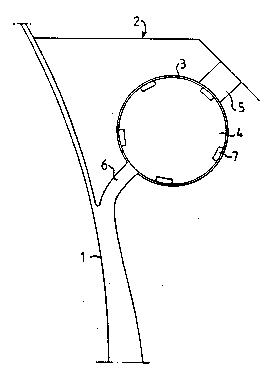
Fig. 1 shows a pulp inlet to a concentrstor sccording
~to the invention,
~ig. 2 shows the surface o~ a rotor provided in the
pulp inlet,
Fig. 3 shows a detsil of the rotor surfsce according
~to a section III-III in Fig. 2,
Fig. 4 shows sn slternative configuration of the pulp
inlet.
Fig. S shows an alternative configuration of the rotor surface.
The device comprises an open-work movable surface 1, on
which the pulp suspension is intended to be formed. The
movable surface can be a perforated roll, wire or the
like. A pulp inlet 2 is provided for the supply Or the
suspension. The pulp inlet 2 is formed with a cylindric
chamber 3, which encloses a cylindric rotor 4 rotatable
about it5 shaPt. The chamber 3 and rotor 4 are located
transversely to the flow direction of the pulp and have
a length substantially corresponding to the width of the
movable surface 1. The chamber 3 i~ provided with an
inlet 5 and an outlet 6 located substantially directly
in front of each other.

W093/W2~ 2~ ~ 41~ ~ PCT/SE92/00469
The cylindric rotor 4 is provided on its surface with a
plurality of cross-wise arranged channels 7. The channels
suitably are arranged helicoidally with opposedpitch
angles. The channels can be arranged so that the crossings
form a right angle or nearly a right angle. Due to the
fact, that the rotor 4 is enclosed with a small clearing
by the chamber 4, the pulp suspension is forced to flow
through the channels 7.
The rotatable rotor 4 suitably rotates at a low rotation
speed, for example 1-20 rpm. The driving of the rotator
should be reversible. The rotor diameter can be 50-100 mm.
The channels are to be dimensioned so that the pulp
suspension flows at a su~ficient rate. The cross section of the
channels 7 can ~e of different design, for instance with rectangular
(fig 2 and 3) or triangular cross section (fig 5). A suitable size of
rectangular channels can be a width of 2-10 mm, preferably 3-7 mm, and
a depth of 2-8 mm, preferably 3-6 mm.
The device operates as follows.
The pulp suspension is supp.l.ied through the pulp inlet 2, whereby the pulp
flows via the inlet 5 of the chamber 3 in~o the channels 7, passes through
the~ same and flows out through the outlet 6 of the chamber 3. The outlet
6 communicates directly with the movable surface 1.
The pulp flows through the channels 7 at a high rate, which
at every crossing between the channels 7 is increa,sed
;instantaneously and thereby gives rise to intensive turb-
ulen~ce.~Flocculation of the pulp is thereby prevented,
and lumps already formed are broken up. Due to the rotation
of the rotor 4 about its shaft at a low speed of rotation,
continously or reversed, the flow direction through each
channel 7`changes periodically. Clogging of the channels
is thereby prevented. The rotor speed æhall be so low in
relation to the flow rate of the pulp through the channels
7, that the flow in one direction or the other about ;~

W093/042~ PCT/SE92/OW69
2~ 3e :~
the rotor 4 is of substantially equal size. The rotor
thereby is not subjected to uneven load, and at the same
time the ~ormation of fibre lumps is prevented in an
optimum manner.
According to the embodiment shown in Fig. 4, an outer
return line 8,9 is coupled between the outlet 6 snd inlet
5 of the chamber 3. In this line 8,9 a pump 10 is located.
This arrangement has the obje~tto maintain in the channels
7 a flow rate higher than correæponding to the capacity
of the concentrator. A portion of the pulp flow is then
circulated through the line 8,9 from the outlet 6 to the
inlet 5. In this way, a homogenous flow of pulp free
from fibre lumps to the formation zone on the movable .
surface 1 is ensured, irrespective of the capacity of
the concentrator.
The invention, of course, is not restricted to the embod-
iments described and shown, but can be varied within the
scope of the invention idea.

Representative Drawing
A single figure which represents the drawing illustrating the invention.
Administrative Status

2024-08-01:As part of the Next Generation Patents (NGP) transition, the Canadian Patents Database (CPD) now contains a more detailed Event History, which replicates the Event Log of our new back-office solution.

Please note that "Inactive:" events refers to events no longer in use in our new back-office solution.

For a clearer understanding of the status of the application/patent presented on this page, the site Disclaimer , as well as the definitions for Patent , Event History , Maintenance Fee  and Payment History  should be consulted.

Event History

Description Date
Inactive: IPC from MCD 2006-03-11
Time Limit for Reversal Expired 1995-12-25
Application Not Reinstated by Deadline 1995-12-25
Deemed Abandoned - Failure to Respond to Maintenance Fee Notice 1995-06-26
Inactive: Adhoc Request Documented 1995-06-26
Application Published (Open to Public Inspection) 1993-03-04

Abandonment History

Abandonment Date Reason Reinstatement Date
1995-06-26
Owners on Record

Note: Records showing the ownership history in alphabetical order.

Current Owners on Record
SUNDS DEFIBRATOR INDUSTRIES AKTIEBOLAG
Past Owners on Record
ALF LINDSTROM
Past Owners that do not appear in the "Owners on Record" listing will appear in other documentation within the application.
Documents

To view selected files, please enter reCAPTCHA code :


To view images, click a link in the Document Description column. To download the documents, select one or more checkboxes in the first column and then click the "Download Selected in PDF format (Zip Archive)" or the "Download Selected as Single PDF" button.

List of published and non-published patent-specific documents on the CPD .

If you have any difficulty accessing content, you can call the Client Service Centre at 1-866-997-1936 or send them an e-mail at CIPO Client Service Centre.


Document
Description 
Date
(yyyy-mm-dd) 
Number of pages   Size of Image (KB) 
Abstract 1993-03-03 1 46
Claims 1993-03-03 2 51
Drawings 1993-03-03 2 56
Descriptions 1993-03-03 4 178
Representative drawing 1998-05-25 1 4
Fees 1994-01-23 1 40
International preliminary examination report 1994-01-23 10 184