Note: Descriptions are shown in the official language in which they were submitted.
WO g3/03310 PCr/lJS92/~266
3 ~ ~
--1--
t:OORING AppARA~ru8 U~:ING E:LECq!RON AND
~O~:C:U~R E~:KCITA~IO~N ~ODE
Cross Re~erences to Related Ap~lications
This application is a continuation-in-part of V.S.
Patent application number 195,967 filed on May 19,
1988, (now abandoned), a continuation-in-part of U.SO
Patent application number 664,494 filed on March 5,
1991, and a continuation-in-part of U.5. Patent
application number 07/350,024 filed on May 12, 1989,
which are incorporated herein by reference.
Field of the Invention
This invention relates to the field of cooking
apparatuses. More particularly, this invention relates
to baking and cooking processes that are substantially
fa~ter than such processes in conventional ovens, and
I offer sensory improvements in quality for many
¦ foodstuffs.
. Back~round of the Invention
Ovens Por cooking and baking food have been known
and used fcr th~ousands of years. Basically, oven types
can be categ~rized in four different forms. The
simplest and probab~ly the oldest cooking resulted when
l man put some vegetable or grain products on a hot rock
J next to a fire~, and cooked them essentially by the heat
2 5 transf er me~hod of conduction. With a little more
refine~ent, an enclosure surrounding the heating
~ element entrapped the heated air gi~iny rise to cooking
'` by convective heat transfer. This was the prototype
,' f or the modern g~s or electric oven . In the past
century, radiant energy from infrared radiation sources
has been used to heat and cook f oodstuf f s directly .
Within the past f ew decades, micrc)wave radiation has
.
W093/03310 PCT/~S9 /0~26~
.
~ 21,1431S
--2--
proved useful in allowing very short cooking times for
many types of food.
There are subtle diferences between c09~ing and
baking~ Cooking just requires the heating of the food.
Baking of a product from a dough, such as bread, cake,
crust, or pastry, re~uires not only heating of the
product throughout but also a chemical reaction coupled
: with driving the water from the dough in a
predetermined fashion to achieve the correct
consistency of the final product and finally browning
the outside. Following a recipe when baking is very
important. An attempt to decrease the baking time in a
conventional oven by increasing the temperature results
in a damaged or destroyed product.
~`( 15 In general, there are problems when one wants ~o
cook or bake foodstuffs with high-quality results in
the shortest times. Conduction and convectioSn provide
the necessary quality, but both are inherently slow
energy transfer methods. Infrared radiation can
provide faster heating rat~s, but it only heats the
surface area of most foodstuffs, leaving the internal
heat energy to ~e:transferred by much slower
. conduction. 'Microwa~e radiation heats the foodstuff
very quickly in depth, but during baking the loss of
~;, 25 . water near the surface.stops the heating process before
.i any satisfactory browning occurs. Consequently,
~, microwave ovens cannot produce quality baked
~, foodstuf~s, such as bread.
~6,` SummarY of the Invsntion
1':'`
An oven for the high-speed, high-quality cooking
. and baking of~food items includes a means for impinging
~` ~ high-int nsity:~isible, near-visible, and infrar~d
radiations ontoS a food item, thereby cooking the item
at accelerated rates comparable to microwave cooking,
Y''
~ .
.. .. . .
~ WO93/0331~ PCT/~S92/062~6
~119L315
.. . . . .
3--
while maintaining the browning of infrared cooking and
the quality of conduction-convection cooking.
It has generally been believed that radiation with
wavelengths much shorter than 1.35 ~m is not of much
value in cooking or baking processes. This
presupposition is based on the fact that water is the
major constituent of most foodstuffs and water is
essentially transparent for wavelengths of
electromagnetic radiation less than about 1.35 ~m.
This region of low energy absorpti~n in water includes
th~ visible (.39 to .77 ~m) and the short infrared ~.77
to 1.35 ~m) which we term "near-visible". The
absorption characteristic of water in the visible and
ne~r-visibl~ regions of the spectrum i5 illustrated in
the graph of Figure 1 using data compiled from the
Handbook of Optics. Because of the low absorption,
radiation at these wavelengths provides very povr
energy transfer to the water, especially in the visible
ra~ge where less than one percent o~ the radiant power
is converted to heat in a one centimeter depth of
water. For this reason, one of ordinary skill in the
art would be predisposed to cook with the longer
-- infrared wavelengths to heat the water in various
foods. - ~
Accordingly, another mode of cooking must be
utilized in ~e present invention. The foodstuff
molecules themselves have very definitQ handc of
absorption in both the visible and near-visible
: xegions~ In the visible regio~ this~absorption shows
up as food color. For example, tomatoes absorb all of
the blue and gr n components of the white light that
illuminates t~em, and they reflect the red portion back
to the eye. Hence we see a "red" tomato~ This color
absorption is due to the excitation of specific
electrons that make up the molecules in a particular
W093/03~10 PCT/US92/Q626~
'2i.1,~31~
--4--
foodstuf~, and it is this absorption that makes it
possible to use intense visible and near-visible
radiation to heat the foodstuff molecules directly. If
one provides a su~ficiently intense source of visible
and near-visible radiation in conjunction with the
~ longer infrared radiation, a novel and very effective
:' cooking apparatus results. The low absorption of
. visible ~nd near-~isible radiation allows the energy to
penetrate the foodstuff and heat it deeply like
~, 10 microwave energy. ~y contrast the longer infrared
radiation does not penetrate very deeply and acts as a
very effective browning agent. By combining these
sources of radiation into a single cooking process it
1 is possible to produce a very rapid and highly
1 15 e~ficient method of cooking and baking a wide variety
;~ of foodstuffs.
As an illustration of the effectiveness of this
~ combined direct:heating pro~ess one ran consider a
:~ simple example.: A cup~(8 oz.~ of pure water in a
~ 20 transparent ¢ontainer can:be heated~to boiling in a
.' time of 35 secondæ in our oven using ~ KW of power.
This can be~compared to the 210 seconds that it takes
to.heat-the same:cup of water in a standard 600 watt
microwave oven. Since water is transparent to the
l 25 visible and::near-visible~radiations, virtually all of
.1 khe heating is~produced by the infrared longer than
1035 ~m. If that cup of water is replaced by an
! identical cup of water, but with a teaspoon of instant
coffee added~:to color it, the boiling time is reduced
~o 25 seconds in our oven, while the microwave oven
~` still requires 2~0 seconds. The coffee r;olecules
themseIves are directly absorbing the impinging energy,
and the visible and near-visible radiations are
~ contributing to the heat rise.
,~
; , ' W093/033~0 PCT/US92/06266
3 ~ ~
i . .
-5-
Radia~t cooking methods can be classified by the
manner in which the radiation interacts with the
foodstuff molecules. This interaction i8 illustrated
for ~arious wavelengths in Fig~re 2. For exampl~,
f 5 starting with the longest wavelengths for cooking, the
~ microwave regisn, most of the heating occurs because of
¦f the coupling of radiant energy into the bipolar water
~ molecule causing it to rotate and thereby absorb energy
,l to produce heat. Decreasing the wavelength to the
~l 10 infrared regime, we find that the molecules and their
!~ component atoms resonantly absorb the energy in well-
~ defined excitation bands. This i5 mainly a vibrational
f energy absorption pro~ess. In the near-visible and
visible regions of the spectrum, the principal
absorption mechanism is excitati~n of the electrons
that c~uple the atoms to form the molecules. These
interactions are easily discerned in the visible band
of the spectra, where we identify them as "colorl'
absorptions. Finally, in the ultraviolet, the
~JI 20 waveleng~h is short enough, and the energy of th~
~l radiation is su~ficient to actually remoYe the
. ~ electrons:from their component atoms, thereby creating
ionized:~states. This short wavelength ultraviolet,
while it finds uses in sterilization techniques,
~l 25 probably has little use in foodstuff heating~ because
it pr~mo~es chemical reactions and destroys food
molecules.
Using intense visible, near-visible, and infrared
radiation to cook food has a number of significant
adYan~ages. First of all, the cooking process is very
fast. Baker~ products, like pizza crust ~or example,
~: can be ba~ d 5 to 10 times faster than ovens tha rely
on con~entional convection and conduction processes
only. Second, the quality of the cooking process is
enhanced for many foodstuffs. For example, crusts
,
r
l`
~;
~,1
~ WOg3/03310 PCT/~92/0~26~
~1431.5
--6--
become fully cooked with crispy exteriors and moist,
ch~wy interior~. Vegetables are cooked so fast that
they are virtually stzamed in their own water vapor,
leaving them hot, but with very little lois of any of
their nutriti~e values. Third, the process is very
energy efficient. Because the oven has reflective
inner walls, most of the energy produced by the sources
is used to cook the food rather than heat the oven. A
pizza can be fully baked for about $.01 o~ ~lectrical
energy.
Ordinarily, in the preferred oven configuration,
the visible, near-visible and infrared impinging means
, is one or more guartz-halogen tungsten lamps, or
equivalent means such as quartz arc lamps~ Typic~l
quartz-halogen lamps of this type, operating at 3000
degrees Kelvin, convert electrical energy into black
body radiation having a range of wavelengths from .4 ~m
to 4.5 ~m with a peak intensity at .965 ~m. Each lamp
can generally~provide from 1 to 2 KW of radiant energy
ii 20 with a signif icant portion of the energy in the visible
`' light spectrum.
.~1 Typical con~igurations can use one to as many as
ten lamps operated in unison, and larger ovens could
use even ~ore:lamps. One or more of the radiation
source lamps may be used in the cooking process as
necessary. ~These radiation sources are ordinarily
~ positioned above and below ths food item. Certain
;I applications~may require that radiation sources
surround the food item. The walls of the surrounding
food chamber are preferably treated to be highly
reflective to~this radiation. The visible and infrared
~i ~ waves from the radiation sources impinge directly on
the food item and are also reflected on this inner
surface of the oven to strike the food item many times
~ 35 and from many angles. This reflecting action results
';
~ WO93/03310 PCT/US92/06266
r 211~3315
--7--
in a greater unif ormity of cooking, and ince very
; little of the radiation is absorbed in the surrounding
reflecting surface, almost all of the radiant energy is
converted into heat upon and within the foodstuff.
Hence, this process is a very efficient mode of
, transferring energy to the foodstuff ~or cooking, and
,~l operation is very economical.
For certain cooking applications, the food item
may be placed on a radiant energy absorbing and h~at
. 10 conductive support platter. The platter can be
:. selectively heated by means of the bottom set of lamps
to increase its temperature to a point where it can aid
the cooking process by conductive heating, if desired.
The platter may be perforated in such a m~nner so as to
facilitate the removal of internal water vapor and
, gases from the bottom sf the foodstu~f.
l The in~ensity of the radiation from the lamps is
ql controllable~ Each lamp can be individually controlled
or the lamps can be operated in uni~on to provide the
desired cooking result. It is necessary that this
~, control be performed quickly, because of the inherent
speed of the cooking process. For certain food
products, it is necessary that the intensity be varied
throughout the~:cooking cycle. Such fast and variable
intensity control is preferably managed through
aut~matic means,:~such as computer or microprocessor
circui~s.
In general, this is a new mode of cooking. The
potentialit:ies of using this enhanced range of
~i 30 wavelengths for:cooking and baking are just starting to
be explored, and a whole new range of cooking
: techniques should resu~t from the invention.
.
! ~ :
:~"
~`1
t
i~.
.
~ WO93/03310 PCT/USg2/06~66
'2,1 14315
. -8-
~rie~ Description of the Drawinas
Figure 1 is a graph showing the ab~orption of
water at various wavelengths of electromagnetic
. radia~ion.
i 5 Figure 2 is a schematic representation showing
various modes of electromagnetic absarption.
Figure 3 shows a front cross section of a
preferred embodiment o~ the present inventisn.
Figure 4 is a graph showing the depth of
penetration of electromagnetlc radiation into watsr
versus wavelength.
.~ Figure 5 is a graph showing cooking time versus
; diameter-squared of a pizza.
Figure 6 sh~ws a side cross section of the
preferred embodiment of the present invention.
Figure 7 is a graph showing the approximately
~ inverse linear relationship between cooki~g power and
;' - cooking time.
. : Figure 8 is a graph showing the constant
; 20 power-time~product for baking a pizza in the oven of
j : the preferred embodiment.
;
::. Det~ailed Description_of the Preferr~d: EmbQdiment
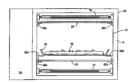
Fig~ 3 is a front ~ross section of the preferred
: ~mbodiment of the present invention. The oven in
~-Fig.: 3 includes~an outer enclosure 10. The enclosure
has an inner wall 12 coupled to the outer wall 10~
~$, ; Ordinarily, an insulating layer 14 is formed between
the outer enclosure~lO and the inner wall 12. Because
of the~inherent:speed of the cooking cycle, the
insulating layer~l4 may be a layer of air.
l .
The present~invention has been used to cook pizzas
:reasonably continuously for an hour in an oven with
: onl:y air as an insulator. While the exterior of the
oven did warm up, it never became too warm to touch
~ . W~93/03310 P~T/US92/06266
~ t~ 3 1 ~
_g_
comfortably. This is true because the interior walls
of the oven are re~lective so that most of the energy
i~ used to cook the food, not heat the oven. Second, a
f an is used to pull hot air out of the oven. Though
some air is heated directly by the radiation, most of
the air is heated by convection from the cooked food.
In prior art convection ovens, hot air is forced onto a
~ood product and acts to cook the food. Commercial
! pizzas are o~t~n cooked this way. Because the cooking
times are so short with the present invention, the hot
air is removed to prevent further cooking after the
radiation source is turned off.
The energy for cooking is supplied by the lower
radiation heating lamps }6 and the upper radiation
; 15 heating lamps 18. Thes~ lamps are generally any oX the
quartz body, tungsten-halogen or quartz arc lamps
commercially available, e.g., 1.5KW 208V quartz-halogen
lamps. The oven according to the preferred e~bodiment
utiliæes ten such lamps and cooks with approximately
1 20 40% to 50% of the energy in the visible and near-
: visible light portion of the spectrum, which is
significant. Quartz xenon-krypton arc lamps have been
used as an alternate source in which 95~ of the
radiation is below l~m and good cooking re~ults have
been achieved with their shorter wa~elengths.
There is no precise definition for the range of
wavelengths for ~isible light because the perceptive
ranges of each human eye is different. Scientific
definitions typically encompass the range of 0~39 ~m to
`~ 30 0~77 ~m. An engineering shorthand for visible light: specifies the range of 0.4 ~m to 0~7 ~m. The tQrm
~! near-visible has been coined for radiation that has
~ wavelengths longer than the visible range, but less
-l than the water absorption cut-off at 1.35 ~m.
,
"
, .
!
I WO93/03310 PCT/VS92/06~
211431~
--1 0--
, Figure 4 is a graph showing depth of penetration
of electromagnetic radiation into water relative to the
wavelength. Please note that the vertical scale is
logarithmic. The d~pth o~ penetration for the visible
light range is in excess of 100 cm (1 m~ter) which is
substantially larger than any ordinary food product.
Because food is mostly water, one would expect the
shorter wavelength radiation of visible light to simply
pass through food. In fact, it is the color absorption
bands of most foods that absorb the radiation and
convert the radiant energy into heat and the high
penetration provides heating deep into the foodstuff.
Alternately, the long infrared has a very small
penetration (less than ~ mm) and this provides high
surface temperatures and good browning characteristics.
The inner surface of the inner wall 12 is
preferably a highly polished, poorly absorptive
surface, so that it appears to~be very reflective to
the wide spectrum of wavelengths from the radiant
- 20 lamps. ;Polished Aluminum~and;stainless steel have been
successfully~used~for the inner wall 12. Plating the
inner~wall~l2,~ such ~as with~gold, increased the
ef~iciency~of~the~reflector~for visible light by about
10% ovér the~polished~Aluminum or~stainless steel
: : :
walls.~
The oven efficiently uses the generated radiant
energy. Figure 5 shows a graph relating cooking time
to diameter-squared of a pizza. The pizzas were all
loaded with~similar ingredients to approximately the
~ same dépth so that area (which is~proportional to the
diameter-squaredj is proportional to volume. As
expected,~as the~volume of pizza to be cooked
increased, the coo~ing time also increased. This graph
~shows two surprising results. First, the graph is
3s linear. In other words, the cooking time is directly
~/U~ g 2 / li b 2 6 6
211~31~ ~ ~ 7 ~E~ ?g~3
proportional to volume (all pizzas were of the same
height). This indicates tha~ nearly all o~ the radiant
energy goes into cooking the pizza. Second, the graph
passes approximately th~ough zero. In conventional
ovens one would expect a displacement of the line up
the vertical axis to account for inefficiencies in th~ -
cooking proc~ss.
Two radiation transparent plates 20 and 24 are
used to isolate the cooking chamber from the radiant
sources making the oven easier to clean as shown in
Figure 3. These plates can be formed from s~ch
materials as quartz or a glass that transmits visible,
near~vi~ible and infrared radiations. The lower
transparent plate 20 is supported by brackets 22a and
~5 22b and is positioned above the }ower lamps 16. The
upper transparent plate 24 is support~d by bracke~s 26a
and 26b and is positioned below upper lamps 18.
Brackets 28a and 28b support platter 30. The
platter 30 is positioned above th~ lower transparent
plate 20 and below th2 upper glass plate 24. A food
item 32 is positioned on platter 3~: to be cooked~ The
sontrol circuit 34, shown as a circuit block, controls
the operation:o~ lamps 16 and 18.
The platter 30 may formed o~ a material similar to
tha transparent plates 20 and 24 to allow even cooking
over ~he surface of the ~ood item 32. However, in some
circumstances it m~y be desirabl~ to crisp the bottom
o~ the ~ood item 32. As a particular example, when
cooking a pizza, it is desirable that the crust be
light and crispy, rather soggy and doughy. In such an
application, the cooking platt~r 30 can be fsrmed of a
radiation absorbing, heat conducting mat~rial, such as
~ ~ bl~ck anodized aluminum. In this way, the lower lights
i 16 would rapidly heat the platter 30 to a high
temperature in order to crisp and brown the bottom of
SUBSTITUTE SHEET
WO93/~3310 PCT/V~92/06266
. . 5
3l~
.
-12-
the pizza. It may also be desirable to perforate the
platter 30 in order to allow steam to escape ~rom the
cooking pizza ~ough. Platter 30 should touch the
support brackets 28a and 28b over very limited areas,
so that the heat delivered to platter 30 is not lost by
conduction.
The lamps 16 and 18 produce very high intensity
visible and in~rared radiation. Prior art uses of
radiant energy heat sources teach cooking using
radiation in the infrared portion of the
electromagnetic spectrum. For example, see Malick U.S.
Patent 4,481,405 and Bassett U.S. Patent 4,486,639.
Burkhart, in U.S. Patent 4,516,486t discloses a radiant
I energy cooker for the exclusive purpose of charring the
surface of foods, particularly meats.
I The use of high intensity vi~ible radiation
f provides a very rapid method of high quality cooking
and baking both alone or in combination with infrared
radiation.~ The radiant energy from the lamps 16 and 18
radiates from each bulb in all directions.~ ~A portion
: of the energy radiates directly onto the food item 32.
The remainder of the energy will be reflected off the
surface of~t~:e preferably metal inner wall 12 and then
strike~the food item 32 for more e~ficient cooking.
-. It is possible to control the lightæ 1~ and 18
independently with the control circuit 34. The control
circuit 34, shown as a circuit block in Fig. 3, may
include a mi~roprocessor or a microcontroller and
~l a~sociated~memory to stoxe individual cooking r cipes
~: 30 to control proper heating of the food produ~t.
: For example, in cooking a pizza, it may be
de~irable to run the upper lamps 18 at a reduced power
level for a time. For a pizza having fresh vegetables,
this would prevent ~he overcooking of the vegetables
~: 35 making them mushy~ The lower lamps 16 might be
; ` .
,j :
WO93/03310 PCT/US92/062~
,
211431S
-13-
operated at a higher powsr level to make the pizza
crust light and crispy.
Figure 6 shows a side CrOS5 section of the
preferred embodiment of the present invention. In the
prefPrred embodiment, there are 5 lower lamps 16a
through 16e and 5 upper lamps 18a though 18 By
appropriately selecting the lateral spacing between the
lamps relative to the food, even cooking can be
achieved over the entire surface. A door 40 is also
shown.
Experimental results show that cooking with one
s l.SKW lamp above and one below, i.e. impinging a
~ maximum of 3KW of radiant energy onto a pizza, does not
;l achieve the dramatic improvem~nt in speed that is
possible according to the present invention. The oven
in the preferred embodiment includes 5 lamps above and
5 lamps below. This number provides for a maximum of
lSKW of cooking ener~y.
Pizza has been success~ully cooked using a
l 20 modification of the present invention with more
-~ powerful bulbs using total power in the range of 4KW to
. approximately ~OKW. There appears to be no reason
preventing the power ranges in excess of 20XW.. This i5
a significant advantage of the present invention.
Cooking times can be reduced by increasing power. The
only way to increase power in a conventional o~en is to
~' increase temperature which damages the fQod. In a
`, ~ microwave, severe federal restrictions prevent
i increasing the power that can be-delivered to food
: 30 because of the~potential for leakage of the dangerous
~waveS,
While cooking a pizza using total power in excess
of about 4KW an approximately inverse linear
relationship develops between time and cooking power.
In other words, as the power delivered to the pizza is
W093/0331~ PCT/US92/06266
~1 14~1~
14
~, doubled, the time to cook a pizæa is cut in half. This
result is totally unexpected in view of conventional
oven baking where increasing oven temperature to
achieve a higher energy transfer rate results in a
j 5 burnt product which may ha~e an uncooked interior.
¦ Figure 7 is a graph showing the relationship
between cooking time and cooking power for baking four
pizzas at 3.8, 6, 9 and 12~W of power. The raw pizzas
I were essentially identical. While the quality of a
,J 10 pizza is subjective, the four finished pizzas from thisexperiment were all of similar satisfying quality.
Figure 8 is a graph showing the power-time product
versus power for baking a pizza in the oven of the
preferred embodiment. Note that in the preferred o~en
the power-time product is constant and has a value of
~,~ about 470KW-sec.
This cooking:in the linear range of the power-
time product appears to be a function of both the
wavelength~of radiation and the amount of power
: 20 applied. :T~us,~ he specific mecha~ical configuration
of the oven in the preferred embodiment is not critical
. to the invention.~ Rather, it is the combination of the
lamps tha~ provide~at~least a significant portion of
` radiati'on in the v~isible light range in excess of 4KW
2~ (total radiant;~:power)~and impinging the radiation
directly onto:the:~food item of energy which provides
the dramatic speed increase of the present invention.
For exampl~e,:an oven having a reflecti~e inner
surface could~operate according to the present
,
: 30 invention with~a~single;arc lamp capable of producing
suf~icient power in the desired frequency ranges. In
certain circumstances it may be desirable in such a
single source oven to place the food product, such as a
pizza, on a highly thermally conductive pla~ter with
the lamp positioned above the food item. The amount of
!
W093/03310 PCT/US92/06266
!, ' /
211 ~13I5
,, --15--
heating to the bottom of the pizza can be regulated by
heating the platter and by adjusting the ratio o~ the
si.ze of the pizza to the size of the pan. In other
words, the amount of exposed area of the pan would
control the amount o energy absorbed by the pan used
to ~eat the bottom of the pizza.
Microwave ovens cannot be used in cooking high
quality freshly prepared pizza. The commercially
;l available frozen pizzas for microwave ovens are
precooked and then frozen. The pizza is merely heated
;~ to the proper serving temperature in the microwave
' oven, but the result is usually unsatisfactory. A
! higher quality pizza can be baked in a commercial grade
conductionJconYection oven. There, the pizza is placed
directly on the hot floor of the oven to properly crisp
the bottom of the crust (up to 900F in a brick oven~r
~' Unfortunately, the ovens have various "hot" spots and
re~uire constant operator attention to aYoid over or
under cooking the pizza, i.e., consi~tency is a major
problem. Such ovens cook a pizza in 5 to 20 minutes.
~? Conveyorized infrared and hot air convection ovens can
cook a pizza in 5-to 15 minutes, but have great
difficulty in properly crisping the bottom of the
pizza .
A pizza can be cooked using the present invention
in as little as 30 to 45 second~. This sp~ed is vexy
important in the commercial pizza market because it
i~, enables:pizza to be produced in a manner that would
`,~ qualify it as a true fast-food.
: 30 -~ The energy efficiency of the present invention is
illustrated by~the fact that the energy cost to ook
: such a pizza is about $0.01. The majority of the
radiant energy produced by the oven is utilized in
cooking the pizza and after the cooking process is
completed the energy is turned off~ In contrast,
.,
WOg3/03310 PcT/uS92/06266
,
7,1 1~315
-16
conventional commercial pizza ovens must be preheated
to desired cooking temperatures. Ordinarily, the oven
in a pizza restaurant is left on all day, whether
cooking a pizza or not, making the energy consumption
S significant.
Another way of considering this new mode of
cooking, especially for pizza, is determining the
! amount of radiant energy necessary to cook a pizza, per
~ unit time and mass. By impinging approximately 20
j 10 watts/gram of radiant energy in an oven of the
preferred embodiment, a minimal nine inch cheese pizza
can be cooked in about 30 seconds, and a combination
pizza with extra large portions of toppings can be
baked in around 50 seconds. A typical twelve inch
pizza takes about 70 seconds. Because of the inverse
dependence of power and cooking time, a nine inch pizza
I could be cooked in two minutes or less by impinging
about 10 watts of radiant power/gram of ingredients
from the oven~of the preferred embodiment. The
inventors believe that improving the reflective
efficiency of the oven would reduce this cooking time.
The inventors~know of no other~pizza oven capable of
baking a quality piz7a of this diameter in times of
Iess than 5 minutes.
The oven~of; the present invention is not limited
~ ~ to cooking pizzas.~ Certain foods are cooked with more
`~ consistent and reliable results than with conventional
~l techniques. For example, ~ooking vegetabl~s, such as!
broccoli, so that they retain good texture is difficult
~, ~ 30 using prior art techniques~ Generally, such items are
`j~ preferred;al dente. The short cooking t,mes of the
~; present invention, about 20 seconds for broccoli, bring
the product to serving temperature so rapidly that the
vegetable maintains its crisp, firm texture.
:
'~
:~
,i
:
; WO93/03310 PCT/US92/06266
~114'315
-17-
Popcorn is another interesting food that can be
prepared in the oven. If the popcorn kernels are
completely surrounded with a water-filled shield, all
of the long infrared can be removed leaving only the
visible and near-visible wavelen~ths to heat the
kernels. Even with all of the direct water-heating
radiation removed the corn will pop in less than 20
I seconds (3 or 4 times ~aster than hot air poppers).
I This is another example showing the efficacity of the
; lO visible and near-visible radiation for rapidly cooking
food. It is interesting *o note that when the corn
pops, its very low absorbing white color automatically
terminates the radiant heatiny, and the popcorn does
not burn.
Even TV dinners can be defrosted and hPat~d in the
oven. Generally, heating times are one-half to one-
i third of the times required in microwave ovens,
.~ depending on the foodstuff. For example, darkly
colored items like salisbury steaks heat very fast,
while lightly colored items like mashed pctatoes heat
at a slower rate.
The oven o~ the present invention may also be used
cooperatively with other cooking sources. For example,
I the oven of the present invention may include a
`, 25 microwave radiation source. Such an oven would be
ideal for cooking a thick highly absorbing food item
such as a roast beef. The microwave radiation would be
u~sd to cook the interior portions o~ the meat and the
infrared and visible light radiation of the pres~nt
invention would cook the outer portions. Further, the
; oven according to the present invention could be used
with a con~ection oven or with both convection oven and
.
microwave oven cooking sourcesO
The present invention was described in relation to
a preferred embodiment. However, it will be apparent
, .
~ WO93/03310 PCr~US92/~626~
:; i
, ~11431~
-18- .
to one skill~d in the art that one can change the
parameters and ~till practice an invention within the
¦ spirit and scope of the present invention.
;l
~1 ,
:: :
;~
,'.i '' ''
. 1 , ` ' , , ~ ,
~i
.
~ ~ ,
`i:
`''`
~`: