Note: Descriptions are shown in the official language in which they were submitted.
211 ll32~ ~
. ~ ..
PO~ERED RO~ATABLE CURVED INSTRUMENT
This invention relates to surgical instruments,
and in particular to powered arthroscopic surgical
instruments.
Powered arthroscopic surgical instruments
typically include a rigid, stationary outer tube within
which a a rigid inner tube is rotated by a motor. A -~
cutting implement, such as a blade or abrading burr, is
disposed on the distal end of the inner tube. Tissue
10. or bone is exposed to the cutting implement through an
opening in the distal end of the outer tube, and tissue
or bone fragments cut by the rotating blade or burr are
drawn through the interior of the inner tube along with -~
irrigating fluid by the use of suction applied at the
1;- proximal end of the instrument. Examples of such
surgical instruments are described in US Patent Nos.
4203444, 4274414, 4834729 and 4842578, all of which are
assigned to the present applicant.
20. Some arthroscopic surgical instruments are
linear, that is, straight between their proximal and
distal ends. Others are curved to facilitate
positioning the cutting implement against tissue to be ~ -
_ cut without requiring that the instrument be removed
from the body and reinserted through an additional
puncture. In a curved instrument, a region of the
inner tube is flexible to enable the inner tube to
accept the curvature imposQd by the outer tube while
transmitting the torsion applied by the motor to the
30` blade. In both cases, the user changes the orientation
of the cutting implement by rotating the instrument.
~ general aspect of the invention is a surgical
' ~
2 ~ 3 2 3
- 2 - :~
instrument that includes a first member that has an
opening in its distal region for admitting tissue and ~ ~
that i5 rotatable with respect to a base from which the ~ ~.
first member extends to allow the rotational ::
orientation of the opening to be selectively changed
with respect to the axis of the instrument; a second
member is disposed within the first member to transmit ~:`
force to move a cutting implement disposed at its
distal end and cause it to cut tissue that is exposed
to the implement through the opening.
Thus according to the invention we provide a
surgical instrument disposed generally along an axis,
said surgical instrument comprising
a first member that extends distally from a base
and has an opening in a distal region thereof for
admitting tissue,
a second member disposed within said first member
for transmitting force applied to a proximal end
thereof to move a cutting implement disposed at a
distal end thereof and cause it to cut tissue that is
exposed to said implement through said opening, and
means for rotating said first member with respect
to said base to selectively change a rotational
orientation of said opening with respect to said axis.
Among other advantages, the invention allows the
user to change the angle of attack of the cutting
implement tie. rotational orientation at which the
cutting implement i9 exposed to tissue) by rotating the
first member only, without turning the entire
instrument. As a result, the user can maintain the
instrument in an essentially fixed position, while
2 ~ ~ ~ 3 ~
. `:. .
rotationally varying the locations at which cutting
performed. This minimizes the manipulation require of ~ `~
the entire instrument, thereby facilitating the .
surgical procedure and reducing patient discomfort and
the risk of surgical side effects.
Preferred embodiments include the following
f eatures .
In a particular useful embodiment, the first
member is provided with a bend region that angularly
offsets the distal region (and hence the opening) from -
the axis of the instrument in a selected direction. In
other words, the instrument is curved. The curved -~
nature of the instrument allows the user (eg. a -
surgeon) to position the cutting implement adjacent to
tissue and other body material that is relatively
difficult to reach with a straight instrument without ~-
having to remove and re-introduce the instrument
through additional incisions in the body. Because the ~ -
first member (rather than the entire instrument) is -~
rotated to vary the angle of cutting attack, the
cutting implement is maintained in close contact with
the tissue being cut at all times.
. .
In the curved embodiment, the first member is
relatively flexible, at least in the bend region, to
allow the rotational orientation of the opening to be
changed without changing the direction of the offset,
and at least a portion of the second member that is
disposed in the bend region is also relatively flexible
to transmit the applied force through the bend region
to the cutting implement.
3 ~ 3 ~
: .
- 4 -
Thus, only the outer member, and not the bend
region itself or the remainder of the instrument, is
rotated to change the orientation of the opening.
Eliminating the need to rotate the entire instrument is
particularly useful with a curved instrument, because
the distal region of the instrument is on an axis
different from that of the remainder of the instrument.
As a result, with a curved instrument in which the
outer tube is nonrotatable with respect to the
10. remainder of the instrument, the entire instrument must
be pivoted or swung about the axis of the distal region
of the instrument to rotate the cutting implement
opening. By contrast, the present invention allows the
instrument to remain in fixed position while the
1;. opening for the cutting implement is rotated. This
simplifies operation and reduces the trauma to the
body.
The first member is relieved in the bend region
20- to provide the relative flexibility. Preferably, the
first member is a tube having rigid proximal and distal
regions that are connected by the relieved portion.
The first member is relieved with a plurality of
discrete openings disposed in its walls. The openings
are a series oS axially spaced, circu~ferentially
extending slots that extend radially into the first
member. Ad~acent slots extend into the first member
from opposite directions. The conSiguration and
orientation of the slots help ensure uniform
Slexibility while providing the Slexible reqion of the
Sirst member with suSSicing torsional stiffness to
transmit rotation applied by the user at, eg. the base
through the bend region to rotate the opening. A
. : . ~i. . ..
3 2 9
-: ....
- 5 - ` ;
pliable sheath (such as a shrink-wrap tube) may be
disposed over the first member in the bend region to
cover the openings.
The second member also is a tube having rigid
proximal and distal ends, and the portion of the second -
member that lies within the bend region is relieved
with a series of axially spaced, circumferentially -
extending slots to provide the relative flexibility. A
motor applies the force as torque to the proximal end
of the second member, and the slotted flexible portion
is confi~ured to transmit the torque through the bend
region to rotate the cutting implement (which is, eg. a
blade). In one embodiment, pliable material i5 ` `-. .
disposed in some or all of the slots. The pliable - - ~-
material helps avoid tissue fragments severed by the -~
cutting implement (which, together with irrigation
fluid, are removed by suction from the surgical site
through the second member) from becoming lodged on the
edges of the slots. The pliable material also reduces
the axial compressibility of the inner tube and leaks
in the suction applied to the proximal end of the inner
tube.
Thus according to the invention we also provide a
surgical instrument disposed generally along an axis,
said surgical device comprising
a first member that extends distally from a base
and has an opening in a distal region thereof for
admitting tissue,
means for providing said first member with a bend
region that angularly offsets said distal region from
said axis in a selected direction,
: ~ .:
- ' ''." '
.. - ,.. .. ,.. ~ ., ... ~ ,,,
~ - ~ . - . , .: : .
1329
a second member disposed within said first
member, for transmitting force applied to a proximal
end thereof to move a cutting implement disposed at a
distal end thereof and cause it to cut tissue that is
exposed to said implement through said opening, at
least a portion of said second member that is disposed
within said bend region being relatively flexible,
means for rotating said first member with respect
to said base, said first member being relatively
flexible at least in said bend region to transmit said
rotation through said bend region to selectively change
a rotational orientation of said opening with respect
to said axis without changing said selected direction
of said offset.
l; .
The bend region is provided by a rigid member
that is disposed coaxially with the first and second
members and is curved in the bend region. The rigid
member radially separates the first member from the
2 second member at least in the bend region. This helps
avoid interference between the flexible regions (eg.
the edges of the slots) as the second member moves.
Preferably, the second member is disposed within the
rigid member, which is in turn disposed within the
first member.
The rigid member has an open distal tip disposed
proximally of the cutting i~plement and opening, and
the ~irst and second members are configured to contact
each other distally of the tip to maintain the cutting
implement in tissue cutting relationship with edges of
the opening. A portion of the distal region of the
first member has a reduced inner diameter with respect
.:. ~. .
~; ' , :
,." , ' ' : ' . ,.
.
. ' , . :
2~1~323 :
to the remainder of the first member to provide the -
contact with the second member and abuts the tip of the
rigid member. The reduced inner diameter equals the
inner diameter of the rigid member to provide a
substantially smooth chamber within which the second
member rotates, thus reducing the risk of the inner
member seizing as it rotates.
The first member is rotatable to allow
10. orientation of the opening to be changed over an arc of
at least 180C, and preferably over a range of 360C. -
The outer tube is rotated manually, using a knob that
is rigidly secured to a proximal end of the first
member and rotatably mounted to a stationary portion of
li- the base. A ratchet mechanism mounts the knob to the ~ -
base to allow the knob to be selectively rotated to a
plurality of discrete positions, thereby to allow the
opening for the cutting implement to be selectively
positioned to a corresponding plurality of discrete
20. rotational orientations.
We further provide a surgical instrument disposed
generally along an axis, said surgical device
comprising,
~5- an outer tube that extends distally from a base
and has an opening in a distal region thereof for - ~-
admitting tissue,
a stationary support tube that extends distally
from a base and is disposed within said outer tube,
said support tube including a bend region disposed
between said ba~e and said distal region to angularly
offset said distal region from said axis in a selected
direction,
Il Z~ 323
- 8 -
an inner tube disposed within said support tube
for transmitting force applied to a proximal end
thereof to move a cutting implement disposed at a
distal end thereof cause it to cut tissue that is
exposed to said implement through said opening, at
least a portion of said inner tube that is disposed
within said bend region being relatively flexible, and
means for rotating said outer tube with respect
to said base about said stationary support tube, said
outer tube being relatively flexible at least in said
bend region to transmit said rotation through said bend
region to selectively change a rotational orientation
of said opening with respect to said axis without
changing said selected direction of said offset.
The stationary portion includes a plurality of - -
recesses each of which corresponds to one of the - -
discrete positons, and the knob has a plunger that
selectively engages the recesses to maintain the
' opening in the discrete rotational orientation that the
user has selected. The knob is resilientiy biased
toward said stationary portion to retain said plunger
in a recess. This helps avoid accidental rotation of
the first member with respect to the base.
::
The proximal end of the second member is secured
to a d~ive sha~t mounted ~or movement (eg. rotation)
with respect to the stationary portion and the knob.
The drive sha~t is driven by a motor to rotate the
second member with respect to the first member and move
the cutting implement. The second member receives
suction at its proximal end to draw tissue fragments
and other body material cut by the cutting implement
2 ~ 2 3 ~
thorugh the second member away from a surgical site
while the instrument remains in situ for futher
cutting.
Other features and advantages of the invention
will become apparent from the following detailed
description, and from the claims.
The invention will now be described with
reference to the accompanying drawings.
Figure 1 shows a surgical instrument according to ~-
the invention, having a cutting implement that is
adjustable to different rotational positions.
Figure 2 is a partial cross-sectional view of
portions of the instrument of Figure 1, showing details
of the tip and base.
Figures 3 - 5 show inner, intermediate, and outer
tubes, respectively, of the surgical instrument of
Figure 1. ~ - ;
Figure 6 is a cross-section of the base of the
surgical instrument, taken along line 6-6 of Figure 2.
Figure 7 shows the surgical instrument of Figure
1 in use.
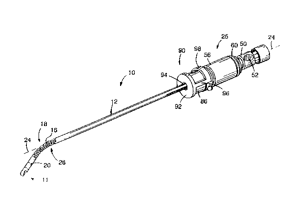
Referring to Figures 1 and 2, surgical instrument
10 suitable for performing, eg. closed, arthroscopy
surgery on the knee with a surgical tool 11, includes
an outer tube 12 within which a rotating inner tube 14
3 2 3
-- 10 --
is coaxially disposed. The distal end of outer tube 12
includes an opening 13, the edges of which are
sharpened and serrated, through which a cutting
implement 15 (formed by sharpened, serrated edges of a
similar opening in the distal end of inner tube 14) of
surgical tool 11 is periodically exposed as inner tube
14 rotates. A rigid, stationary intermediate tube 16
is disposed coaxially between outer tube 12 and inner
tube 14. Intermediate tube 16 is curved through a bend
region 18 disposed slightly proximally of the distal
end 20 of tube 16 to angularly offset surgical tool 11
from a generally straight axis 24 of surgical
instrument 10. Bend region 18 enables surgical
instrument 10 to operate on surgical areas that are ~-
difficult to reach with a straight instrument.
Tubes 12, 14 and 16 are proximally supported by a
base 25. As discussed below, inner tube 14 includes a
slotted, flexible region 26 disposed within bend region
18 to accept the curvature imposed by bend region 18
and transmit torque (and other forces) applied at base
25 through bend region 18 to rotate cutting implement
15 with sufficient force to sever tissue or other body ~-
material exposed through opening 13. Outer tube 12 has
a slotted, flexible region 28 that envelopes bend
region 18 and allows the user to rotate outer tube 12
with respect to base 25, despite the curvature imposed
by bend region 18. This feature enable~ the user to
selectively change the rotational orientation of
opening 13, and hence surgical tool 11, with respect to
axis 24 without rotating the entire surgical instrument
10, and thus without changing the orientation of bend
region 18 and the angular offset that it provides. As
.
21~32~ ~
1 1 --
a result, the user can maintain surgical instrument 10 ~:
in an essentially fixed position, while changing the -~.
angle ~f attack of cutting implement 15 by rotating
outer tube 12.
, . .
Referring also to Figure 3, inner tube 14 is made
from metal, such as stainless steel, and has rigid
proximal and distal regions 30, 32, that are connected
by flexible region 26. Flexible region 26 is relieved
with an axially extending series of circumferential
slots 34 disposed in the walls 36 of tube 14 and is
continuous with the adjacently disposed proximal and .
distal regions 30, 32. (Slotting a rotatable tube for :~
flexibility is described in a copending application
entitled "Surgical Instrument", Serial No.07/634599,
filed on 27 December 1990, assigned to the present
assignee and incorporated herein by reference). Slots
34 are perpendicular to the longitudinal axis 38 of
tube 14 and are arranged in a symmetrical pattern along
the length Ll of flexible region 26 to provide uniform
flexibility as inner tube 14 rotates. This minimizes
torsional stresses on inner tube 14 and helps prolong
the operating life of surgical instrument 10. :~
Slots 34 are disposed parallel to each other
~vertically in Figure 3) along length L1. Adjacent
slots 34 extend into tube 14 from opposite directions
(eg. from above and below tube 14 in Figure 3) and are
circum~erentially of~set from each other by 180. The
number of slot~ 34, their dimensions ~ie. their width
and depth), and the spacing between adjacent slots are
a function of the desired degree of flexibility. For
example, the width of each slot 34 and the spacing
.
211 ~13~3
between slots 34 and the spacing between slots 34 each
are 0.020 inches.
A tab 40 bounds each slot 34 circumferentially,
and adjacent tabs 40 are interconnected by annular
rings 42, which provide the spacing between adjacent
slots 34. The interconnected series of rings 42 and
tabs 40 provide a series of interconnected, integrally
formed "U" shaped leaf springs along the length Ll of
flexible region that give uniform flexibility and
efficiently transmit torque (ie. rotational force)
applied at proximal region 30 of tube 14 to distal
region 32 through the curvature imposed by bend region -~
18 (Figure 1). The depth of slots 34 (ie. the amount
by which slots 34 extend radially into tube 14) is a
function of the desired torsional strength of flexible
region 26. For example, slots 34 have a depth of about -
75% of the outer diameter (0.135 inches) of inner tube
14.
'
The length Ll of flexible region 26 is a function
of the length of bend region 18. Flexible region 26 ;~
should be sufficiently long (eg. 0.70 inches) so as to
span the entire length of bend region 18, with adjacent
rigid regions 30, 32 lying within straight regions of
stationary intermediate tube 16. This allows flexible
region 26 to make a smooth transition between the
straight regions o~ intermadiate tube 16 and bend
region 18, thereby reducing stresses imposed by the
curved inner walls of bend region on walls 36 of inner
tube 14.
Flexible region 26 can be formed by any suitable
~ f-'~329
method. Examples include wire EDM (electric discharge
machining) and sawing. Both are described in the -
aforementioned US Patent Application Serial ~-
No.07/63459s.
Distal region 32 of inner tube 14 supports
cutting implement 15 (which is, for example, stainless
steel and attached to tube 14 by welding or brazing).
Cutting implement 15 is defined by serrated, sharpened
10. edges 44 of a distal openinq 46 in tube 14 and is sized
to provide a close running fit with the distal end of ~-
outer tube 12 for efficient cutting. Opening 46 is an -~
extension of a central aperture 48 in inner tube that
runs the entire length of tube 14.
5 .
Proximal region 30 of inner tube 14 is rigidly
mounted to a drive shaft 50 that rotates within base
25. Central aperture 48 terminates in a vacuum source -
opening 52 in drive shaft 50. The proximal end 53 of
20- drive shaft 50 fits into a handpiece 110 (Figure 7),
which includes a motor 112 for rotating drive shaft 50
and inner tube 14 with resepct to tubes 12, 16. One
example of such a handpiece is described in US Patent
No.4705038, entitled "Surgical System for Powered
Instruments", and assigned to the present assignee,
which is incorporated by reference. Opening 52 is
coupled to a vacuum source 114 ~Figure 7) during
operation to remove severed tissue and irrigating fluid
from the surgical site via aperture 48 in a manner
described in detail below.
Figure 4 shows intermediate tube 15 (before bend
region 18 is formed), which is made from a rigid
211 ~32~ ~
- 14 -
material such as metal (eg. stainless steel).
Intermediate tube 16 is hollow along its entire length
to provide a passage 54 that receives inner tube 14,
which protrudes through the open distal end 20 of
intermediate tube 16 (Figure 2). The inner diameter of
intermediate tube 16 is only slightly larger than the
outer diameter of inner tube 14 (eg. by approximately
0.002 inches); this allows inner tube 14 to rotate
freely but helps minimize wobbling of tube 14 to keep
lO- the sharp cutting edges of implement 15 and opening 13
closely aligned.
The proximal end of intermediate tube 16 is
rigidly mounted to a hub 56 of base 25. A cavity 58 in
15. hub 56 communicates with passage 54 and is configured -
to receive drive shaft 50. During assembly, inner tube
14 is inserted through hub 56 into intermediate tube 16
(before bend region 18 is formed). A pliable fitting
60 retains drive shaft 50 within hub 56. Fitting 60
20- provides a fluid-tight seal when base 25 is inserted
into handpiece 110.
Referring to Figure 5, outer tube 12 is
essentially a larger version of inner tube 14 and
25- includes rigid proximal and distal regions 62, 64 that
are integrally connected by flexible region 28.
Flexible region 28 includes an axially extending series
o~ slots 66 disposed perpendicularly to the
longitudinal axis 68 o~ tube 12 and arranged in a
30' symmetrical pattern along the length L2 of ~lexible
region 28. Adjacent slots 66 extend radially into tube
~2 in opposite directions (ie. from above and below
tube 12 in Figure 5). Each slot 66 is approximately
, , . . - ` ~ ' : :,
2 l 1 ~ 3 2 ~
.
- 15 -
0.025 inches wide and has a depth of about 0.140
inches.
Each 510t 66 iS bounded by a tab 70. Adjacent
tabs 70 are circumferentially offset by 180 and are : .
connected by rings 72 (each of which has the same width
as slots 66) to form a series of "U" shaped spings that
are continuous with each other and with proximal and
distal regions 62, 64. As a result, flexible region 28
is both sufficiently pliable to accept the curvature
imposed by bend region 18 and sufficiently torsionally ~ `
stiff to transmit applied rotational force through bend ~ .
region 18 to rotate opening 13. Length L2 should be
such that flexible region 28 spans the entire length of :
bend region 18, with the adjacently-disposed rigid .
portions 62, 64 of outer tube being aligned with
straight portions of intermediate tube 16.
As shown most clearly in Figure 2, to ensure a
close running fit between sharp edges 44 of cutting : .
implement 15 and the corresponding cutting edges 84 of
opening 13 despite the spacing between tubes 12, 14 ::
that intermediate tube 16 provides, a distal extension
74 having the same inner diameter as intermediate tube
16 is secured to outer tube 12 at distal end 64.
Extension 74 is, eg. stainless steel and is welded or : `
brazed to outer tube 12, which can be a softer
material, such as aluminium. The proximal end of
extension 74 has a reduced outer diameter to allow it
to be disposed within outer tube 12 and about
intermediate tube 16 at joint 76. A shoulder 78 on ~
distal extension 74 limits the amount by which: :`
extension 74 is inserted into distal end 64 during
~ .. ~ j`. .
' ` ' ` ' '~
211l~32~ . ~
- 16 - ;
assembly.
Opening 13 is disposed in a distal tip 80 of
extension 74 and faces somewhat to the side of outer
tube 12. That is, opening 13 does not extend
completely to the centreline 82 of extension 74. As a
result, while surgical tool will cut tissue that enters ~ ;
opening 13 from the distal end of instrument 10, the
majority of the cutting action is to one side.
Moreover, tip 80 provides distal support for the
rotating inner tube 14. The edges 84 of opening 13 are
sharpened and serrated to cooperate with sharp edges 44
of cutting implement 15. The clearance between inner
tube 14 and the inner diameter of outer tube extension
1~. 74 and intermediate tube 16 is small teg. approximately
0.002 inches) to maintain the close running fit between
edges 44, 84 while allowing inner tube 14 to rotate
freely. The identical inner diameters of extension 74
and intermediate tube 16 avoid inner tube 14 scoring or
~' seizing as it rotates. ---
Proximal region 62 (Figure 5) of outer tube 12 is
rigidly secured to a drum 86 at a sealed joint. Drum ~-
86 serves as a knob to enable the user to manually
25. rotate tube 14, and is rotatably mounted to base 25 in
a manner described below. A central passage 88 extends
through outer tube 12 and drum 86 to receive
intermediate tube 16 and inner tube 14. The inner
diameter of outer tube 12 ~proximally of extension 74)
only slightly exceeds the outer diameter of
intermediate tube 16 (eg. by approximately 0.002
inches). This allows the user to rotate outer tube 12
but avoids excessive play between tubes 12, 16.
- '~, .
,~ .
.~
2 1~329
- 17 - `
Referring to Figure 2, outer tube 12 and drum 86 ~
are rotatably mounted to base 25 with a spring-loaded -
rotation assembly 90. Drum 86 is captured between the --
distal end 57 of hub 56 and a faceplate 92, which
includes an opening 94 (Figure 1) through which outer
tube 12 projects. A pair of axially extending bars 96
connect faceplate 92 to a sleeve 98 that is rigidly
mounted to a hub distal end 57 by one or more press-fit
pins 100. A spring 102 (eg. a wave washer), which fits
10. within a recess (not shown) in faceplate 92,
resiliently biases drum 86 toward hub S6.
Referring also to Figure 6 (which, for clarity
does not show tubes 14, 16 in cross-section), distal
1;- end 57 of hub 56 includes a series of ~such as eight)
rounded recesses 104a-104h disposed in an annular
surface 105 of hub 56 that faces drum 86. Recesses
104a-104h are spaced by equal amounts (such as by 45) -
around the circumference of hub 56. Surface 105 is -
flat between adjacent recesses 104a-104h. A plunger
106 having a spring-loaded, ball shaped tip 107 is
threaded into drum 86. Tip 107 is resiliently urged ~-
against hub 56 and into a selected one of recesses
104a-104h by spring 102.
Thus, the user can selectively rotate drum 86 _ ;
and hence outer tube 12 and surgical tool opening 13 _
to one of eight discrete rotational orientations. The
biasing provided by spring 102 maintains plunger tip
107 ln the selected recess 104a-104h to avoid
accidental rotation. As drum 86 is rotated between
recesses 104a-104h, tip 107 is compressed into plunger
106 by flat surfaces 105. Recesses 104a-104h are
. - . ~ , . . - :: -.
:. :........ . ~ ~ .
: - .~ - ~ - :, , ;. . .. . . .
.. , . . ~ . ~ . ~.. . . . . .. . . .. . .. ....
.. . . .. - .... : ::.: ::.. :::
2 ~ 3 2 9
- 18 -
arranged to allow opening 13 to be rotated in a
ratchet-like fashion to commonly used positions with
respect to axis 24. For example, positioning plunger
tip 107 in recess 104a orients opening 13 oppositely
from the direction of curvature of bend region 18 ~`
(Figure 2), that is, is aligned with the curvature
direction and is oriented downwardly (the position
shown in Figure 2). Similarly, recesses 104c and 104g
correspond to left and right orientations. Recesses
104b, 104d, 104f and 104h provide intermediate
positions for opening 13.
Referring also to Figure 7, in operation,
surgical instrument 10 is inserted into the distal end -~
of a handpiece llo and is introduced as shown through a
puncture wound 120 into the knee joint 122, below the
patella. Light is projected into the joint via a
second puncture 124 using a fibre optic light source
126, and a visual image of the surgical site is
returned through a separate optical path to a
television camera 128. The image is delivered by
camera 128 onto a television screen 130 for viewing by
the surgeon. (Alternatively, the surgeon can view the
image using an eyepiece, or the image can be recorded).
The surgeon operates surgical tool 11 by
activating motor 112, which receives operating
potential and current from power supply 116. Motor 112
engage~ and rotates drive shaft 50, thereby applying
rotational force to inner tube 14 and rotating tube 14
with respect to tubes 12, 16. The surgeon controls
rotational speed and direction (either unidirectional
or oscillatory) using foot switches 116a, 116b, which
.
: - .. .
~i :LA~329 ~ :
- 19 - :-
control the magnitude and polarity of operating
potential and current provided by power supply 116 to
motor 112. Motor 112 is capable of rotating inner tube
14 over a wide range of speeds, eg. between about 100 `~
rpm and 5000 rpm, and can deliver a torque of up to 25
oz inches.
Different types of surgical instruments such as
instrument 10 have rotational and torsional limits. To ~
1 prevent the surgeon from inadvertently operating - ~;
instrument 10 at dangerously high speeds and torques,
instrument 10 identifies to sensors (not shown) in
handpiece 110 what type of instrument it is, and the
spped of and torsion applied by motor 112 is controlled
1,. so that these limits are not exceeded. (This control
technique is described in the aforementioned US Patent - -
No.4705038.
:
The torsion that motor 112 provides is
20- efficiently delivered to cutting implement 15 by
flexible region 26. Although region 26 is sufficiently
flexible to accept the curvature imposed by bend region
18, it has a high degree of torsional stiffness and
_ thus provides good torque response. That is, torsion
applied by motor 112 is transmitted to distal region 32
of inner tube 14 substantially immediately when inner
tube 14 is rotated from its rest position, without
requiring any significant "preloading" of flexible
region 26 prior to passing the torgue to distal end 32.
Also, flexible region 26 does not expand in diameter by
any significant amount as it rotates and applies torque
to distal end 32, reducing the possibility that tube 14
will bind within intermediate tube 16 during rotation.
,, ; , . ~' S` ` . . !.
21 ~ ~32~ ~
- 20 -
During the surgical procedure, the body joint is
distended with fluid introduced through a third
puncture wound 132 from a fluid source 134. The fluid
irrigates the site and renders tissue 136 (which is,
eg. synovial tissue) mobile so that it floats and can `~
be displaced (similar to the movement of seaweed in
water). Note that synovial tissue 136 is located
beneath outer tube 12; thus, drum 86 is positioned so -~
that plunger 106 is in recess 104e (Figures 2 and 6).
10. The curvature provided by bend region 18 allows
surgical instrument 10 to be easily positioned to place ~-
surgical tool 11 against tissue 136 (even if tissue 136
is located in a region of the joint that cannot easily -~;
be reached by a straight instrument) without
manipulating instrument 10 unduly or requiring that
additional punctures be made to gain access to tissue
136. This reduces patient discomfort, as well as the
chances for infection and other deleterious -~
consequences of the surgery.
20.
The surgeon progressively cuts away synovial
tissue 136 by moving surgical instrument 10 from side ~-
to side and in the axial direction using handpiece 110
(while viewing television screen 130). If during the ~
procedure the surgeon wishes to cut tissue from another -
region of tbe synovial tissue, such as region 138
located above outer tube 14, the present invention
allows him to do so simply by changing the rotational
orientation o~ surgical tool opening 13 (eg. in the
direction of arrow 140) while maintaining handpiece 110
in a ~ixed position _ that is, without requiring the
surgeon to rotate or pivot handpiece 110.
::
''
2 ~ i ~ 3 ~ ~
-- 2 1
This is accomplished, for example, by grasping
drum 86 with the finger and thumb of one hand (while `
the other hand continues to grasp the body of handpiece
110) and turning drum 86 in the direction in which `
opening 13 is selected to rotate (eg. along arrow 142).
The rotational force applied by the surgeon is
transmitted through bend region 18 by flexible region
28, thereby causing distal extension 74 of outer tube
12 to rotate with respect to intermediate tube 16 and `
base 25 and change the orientation of opening 13 with
respect to axis 24 (in this case, by 180).
In this example, in which tissue 138 is located
above outer tuve 12, the surgeon continues to rotate
drum 86 until plunger 106 rests within recess 104a. As
drum 86 is rotated between recesses, plunger 106 slides
across flat surface 105 and drum 86 compresses spring
102 against faceplate 94. Thus, spring 102 positively
urges plunger 106 into each recess 104 as it is
encountered, thereby giving the surgeon kinesthetic
feedback as to the amount by which opening 13 has been
rotated.
The surgeon can change the rotational orientation
of opening 13 at any time. For example, inner tube 14
can be driven by motor 112 or may be stationary while
the surgeon rotates openinq 13. Distal extension 74
rotates smoothly with respect to the stationary
intermediate tube 16 at joint 76, while providing
constant distal support (at tip 80) for rotating inner
tube 14. The identical inner diameters of tube 16 and
extension 74 help ensure that the rotation of outer
tube 12 does not cause inner tube 14 to bind or seize.
21 ~ ~2~ :
- 22 -
The surgeon can return to cutting tissue 136 at any -
time simply by rotating drum 86, either in the opposite
direction from arrow 142 or in the same direction to
trace a 360 arc from his starting point.
Tissue fragments and other body material cut by
surgical tool 11 are withdrawn fro~ the surgical site ~-
along with irrigation fluid via central aperture 48 of
inner tube 14 (Figure 2) in response to suction applied
by vacuum source 114. Note that as flexible region 26 - -~
rotates within the bend region 18, the width of each
slot 34 at the periphery of tube wall 36 progressively
increases and decreases incrementally with respect to -
its nominal width. This is because flexible region 26
tends to stretch at the apex of bend region 18 (ie. the -
upper part of bend region 18 in Figure 2) and compress --
at the base of the bend. This alternating widening and -~
constricting as tube 14 rotates may generate turbulence
in the fluid being withdrawn through aperture 48, ~ -~
thereby assisting in the transport of tissue fragments :--
through the chamber and out of surgical instrument 10. --~
. ~ .
The exposure of aperture 48 to the interior walls
of intermediate tube 16 through slots 34 has not been
found to allow tissue fragments to become caught in the
slots and cause blockage, perhaps due to the small
width of the slots and ths continual rotation of inner
tube 14. Fluid likewise ha~ not been found to seep
between tubes 14, 16 via slots 34 ~or between tubes 12, ~ -
16) in amounts that interfere with the operation of
instrument 10.
Other embodiments are within the scope of the
2~329 ` :~
- 23 -
` ' ~ ', .,;~
following claims.
For example, although surgical instrument 10 is
shown with bend region 18 orientated downwardly with
respect t~ axis 24 and handpiece 25, it is readily
apparent that other orientations ~eg. downwardly, to
the right or left, or anywhere in between these
directions) are possible. Indeed, a set of surgical
instruments may be provided, each with a different bend
region 18 orientation, to give the user maximum
flexibility in determining tbe optimum bend
configuration for a given surgical procedure other
amounts of curvature can be provided.
Also, as described in the aforementioned patent
application serial no.07/634599, pliable material (such
as silicone rubber) may be disposed in slots 34 of
inner tube 14. (Pliable material is illustrated in
Figure 2 by shaded area 150 within a slot 34 of inner -
tube 14). The pliable material would further help
avoid clogging by reducing the tendency of tissue
fragments to become caught on the edges of slots 34 as
the fragments pass through inner tube 14. Moreover,
the pliable material is less compressible than empty
space, and thus would serve to reduce the axial
compressibility of flexible region 26.
A tube (made from, eg. shrink wrap plastic) may
be placed over outer tube in bend region 18 to cover
slots 66.
~ A portion of such a tube 152 is shown in Figure
2). Among other advantages, a shrink wrap tube will
',
- 27 ~ ~3~ ;
- 24 -
avoid material becoming lodged within slots 66 and help - `~
prevent the edges of slots 66 (which may be sharp) from ~ - -;
causing damage. -
' Surgical tools other than the cutting implement
shown in the figures can be used. For example,
surgical tool 11 need not have serrated edges and may
alternatively be constructed as a bone abrading
instrument. The surgical instrument can be constructed
I to perform procedures other than arthroscopy (such as
laparoscopy). ~;
Inner tube 14 may alternatively be flexible along -
its entire length so long as the tube is sufficiently
~~ stiff to transmit the forces applied to it (eg.
torsion) to surgical tool 11. For example, inner tubes
14 may comprise a nonmetal, such as plastic, and drive
a separate, metal member that carries cutting implement ~ -
15. such a configuration is shown in copending
20- application serial no.07/600531, filed on 19 October
1990, which is assigned to the present assignee and -~
incorporated herein by reference).
While the invention has been described in terms
25- of surgical instruments for arthroscopy, the invention
may also be used with other types of instruments, for
example, instruments configured for other kinds of
endoscopic procedures and ~or biopsy applications.
30.