Note: Descriptions are shown in the official language in which they were submitted.
2L14455
-1
TITLE OF THE INVENTION
DISCHARGE-TYPE IGNITION DEVICE FOR OIL BURNER
BACKGROUND OF THE INVENTION
This invention relates to a discharge-type ignition
device for an oil burner, and more particularly to a discharge-
type ignition device for an oil burner which is adapted to carry
out ignition of a wick of the oil burner by electric discharge.
Conventionally, a filament-type ignition device for an
oil burner which is constructed so as to red-heat a filament by
means of a dry cell acting as a power supply, to thereby permit
the red-heated filament to ignite a wick of the oil burner is
generally used for ignition of the oil burner.
Further, a discharge-type ignition device for an oil
burner is also known in the art. The discharge-type ignition
device is classified into a device using combustion heat
generated from the oil burner as a heat source and a commercial
AC 100V power supply as a power supply for the ignition device
and a device using a battery means such as a dry cell as the
power supply.
The latter discharge-type ignition device using a
battery as the power source for electric or spark discharge is
disclosed in Japanese Utility Model Publication No. 35244/1988,
although it unfortunately fails to be put into practice due to
various disadvantages. The conventional discharge-type ignition
device using a battery as disclosed includes discharge electrodes
arranged so as to be spaced from each other with a combustion
wick being interposedly positioned therebetween.
The present invention is directed to a discharge-type
ignition device of the latter type which uses a battery as a
power supply to carry out spark discharge between discharge
electrodes, to thereby ignite a wick.
The conventional discharge-type ignition device using a
dry cell as the power supply has a disadvantage that the dry cell
fails to permit spark discharge sufficient for ignition of a wick
of an oil burner to occur between discharge electrodes. Also,
the conventional discharge-type ignition device using a dry cell
2114455
-2-
causes a variation in height of the wick and deterioration of a
surface of the wick due to settling of the wick, adhesion of tar
to the wick or the like, and deformation of the wick with lapse
of time, resulting in a variation in dimension between the wick
and the discharge electrodes. This causes spark generated by
discharge to be deviated from the wick, leading to a failure in
ignition of wick and/or generation of white fume of fuel oil from
the wick. This would be the reason why the conventional
discharge-type ignition device using a dry cell fails to be put
into practice.
Thus, an ignition device for an oil burner which is
currently commercially available is limited to the above-
described filament-type ignition device.
Accordingly, it is highly desirable to develop a
discharge-type ignition device using a battery such as a dry cell
which eliminates the above-described disadvantage of the prior
art, because it is essentially free of a disadvantage of a
filament-type ignition device that a filament is readily
exhausted, deformed and/or broken.
SUMMARY OF THE INVENTION
The present invention has been made in view of the
foregoing disadvantage of the prior art.
Accordingly, it is an object of the present invention to
provide a discharge-type ignition device for an oil burner which
is capable of generating spark discharge in the course of upward
movement of a wick for ignition of the wick, to thereby ensure
positive and effective ignition of the wick irrespective of using
of a dry cell.
It is another object of the present invention to provide
a discharge-type ignition device for an oil burner which is
capable of positively accomplishing ignition of a wick
irrespective of a variation in height of the wick, deterioration
of the wick, deformation of the wick and the like.
It is a further object of the present invention to
provide a discharge-type ignition device for an oil burner which
is capable of positively carrying out ignition of a wick by spark
21144 55
-3-
discharge.
It is still another object of the present invention to
provide a discharge-type ignition device for an oil burner which
is capable of effectively accomplishing ignition of a wick even
when spark discharge for the ignition is weak, to thereby permit
a small-sized power supply such as a dry cell to be used for the
spark discharge.
It is even another object of the present invention to
provide a discharge-type ignition device for an oil burner which
is capable of preventing a human body such as a hand, a finger or
the like from carelessly touching a discharge electrode means
during cleaning of the ignition device or the like.
It is a still further object of the present invention to
provide a discharge-type ignition device for an oil burner which
is capable of keeping a distance between a discharge electrode
means and a wick substantially constant, to thereby ensure smooth
ignition of the wick.
It is a yet further object of the present invention to
provide a discharge-type ignition device for an oil burner which
is capable of effectively preventing a side wind blowing against
the oil burner from adversely affecting both ignition operation
and combustion operation.
It is an even further object of the present invention to
provide a discharge-type ignition device for an oil burner which
is capable of being simplified in construction, leading to a
decrease in manufacturing cost.
In accordance with the present invention, a discharge-
type ignition device for an oil burner is provided. The
discharge-type ignition device comprises a wick receiving
cylinder structure including an inner cylindrical member and an
outer cylindrical member arranged so as to be spaced from each
other with a space being defined therebetween, a wick arranged in
the space of the wick receiving cylinder structure so as to be
vertically movable, a wick operating shaft rotated for vertically
moving the wick, a discharge electrode means including a fist
discharge electrode and a second discharge electrode which are
2~14~55
-4-
arranged for generating spark discharge therebetween sufficient
to ignite a portion of the wick raised so as to upwardly extend
from the space of the wick receiving cylinder structure, an
ignition knob for rotating the wick operating shaft in a wick
raising direction, and an ignition switch operated depending on
actuation of the ignition knob. The ignition switch is turned
off when the ignition knob is moved to a wick lowered position
and turned on in the course of upward movement of the wick and
the discharge electrode means carries out spark discharge in the
course of upward movement of the wick.
BRIEF DESCRIPTION OF THE DRAWINGS
These and other objects and many of the attendant
advantages of the present invention will be readily appreciated
as the same becomes better understood by reference to the
following detailed description when considered in connection with
the accompanying drawings in which like reference numerals
designate like or corresponding parts throughout; wherein:
Fig. 1 is a vertical sectional view showing an example
of an oil burner to which a discharge-type ignition device
according to the present invention is applied;
Fig. 2 is a front elevation view showing an embodiment
of a discharge-type ignition device for an oil burner according
to the present invention which is at a wick ignition position;
Fig. 3 is a front elevation view of the discharge-type
ignition device shown in Fig. 2 which is at a fire-extinguishing
position;
Fig. 4 is a fragmentary enlarged sectional view showing
an essential part of a discharge electrode means in the
discharge-type ignition device shown in Fig. 2;
Fig. 5 is a plan view of the discharge electrode means
shown in Fig. 4;
Fig. 6 is a block diagram showing an electric circuit of
the discharge-type ignition device of Fig. 2;
Fig. 7 is a circuit diagram of each of an intermittent
switch circuit and a high-voltage generation circuit in the
circuit shown in Fig. 6;
211445
-5-
Fig. 8 is a fragmentary sectional view showing a
modification of a discharge electrode means;
Fig. 9 is a plan view of the discharge electrode means
shown in Fig. 8;
Fig. 10 is a fragmentary sectional view showing another
modification of a discharge electrode means;
Fig. 11 is a plan view of the discharge electrode means
shown in Fig. 10;
Fig. 12 is a fragmentary sectional view showing a
further modification of a discharge electrode means;
Fig. 13 is a plan view of the discharge electrode means
shown in Fig. 12;
Fig. 14 is a fragmentary sectional view showing still
another modification of a discharge electrode means; and
Fig. 15 is a plan view of the discharge electrode means
shown in Fig. 14.
DETAILED DESCRIPTION OF THE PREFERRED EMBODIMENTS
Now, a discharge-type ignition device for an oil burner
according to the present invention will be described hereinafter
with reference to the accompanying drawings.
Referring first to Fig. 1, an example of an oil burner
to which a discharge-type ignition device according to the
present invention may be applied is illustrated. The oil burner
shown in Fig. 1 includes a wick receiving cylinder structure 20
comprising an inner cylindrical member 22 and an outer
cylindrical member 24 arranged so as to be radially spaced from
each other with a space being defined therebetween. In the thus-
formed space of the wick receiving cylinder structure 20 is
arranged a wick 26 in a manner to be vertically movable. The
wick receiving cylinder structure 20 is mounted on an oil
reservoir 28. Reference numeral 30 designates a wick operating
shaft, which is adapted to vertically move the wick 26 when it is
rotated. On the wick receiving cylinder structure 20 is
supported a combustion cylinder structure 32 in which combustion
of fuel oil takes place. The above-described construction of the
oil burner is widely known in the art.
~1~4~~~
-6-
Now, an embodiment of a discharge-type ignition device
according to the present invention will be described hereinafter
with reference to Figs. 1 to 5.
A discharge-type ignition device of the illustrated
embodiment includes a discharge electrode means 34 comprising a
pair of discharge electrodes or a first discharge electrode 34a
and a second discharge electrode 34b. The first and second
discharge electrodes 34a and 34b are arranged in a manner to be
opposite to a side surface of the wick 26 and/or an upper end
thereof. In the illustrated embodiment, the first discharge
electrode 34a is a positive electrode and the second discharge
electrode 34b is a negative electrode. Also, in the illustrated
embodiment, the first discharge electrode 34a and second
discharge electrode 34b are arranged in proximity to the side
surface of the wick 26 and opposite to an upper end surface of
the wick with a gap being defined therebetween, respectively,
when the wick 26 is raised to a normal combustion position. The
second discharge electrode 34b is preferably arranged in
proximity to the upper end of the wick 26 when it is raised to an
uppermost position defined beyond the combustion position.
The ignition device of the illustrated embodiment also
includes an ignition knob 36 vertically movably arranged and
operatively engaged with a lever 38 provided for rotating the
wick operating shaft 30 and an ignition switch 40 electrically
connected to the discharge electrode means 34 to selectively feed
it with electricity. In the illustrated embodiment, the ignition
knob 36 is provided thereon with an arm-like switch actuator 42,
so that downward movement of the ignition knob 36 may permit the
switch actuator 42 to actuate the ignition switch 40. For this
purpose, the discharge-type ignition device may be so constructed
that the ignition switch 40 may be turned on in the course of
upward movement of the wick 26. Such construction permits
ignition of the wick 26 to be carried out at any appropriate
position of the wick which is not fixed. The ignition knob 36 is
connected to one end of a coiled compression spring 44, resulting
in being constantly biased toward an original position thereof or
~11445~
_,_
in an upward direction as indicted at phantom lines in Fig. 2 and
solid lines in Fig. 3 when it is moved to a wick ignition
position. The other end of the spring 44 may be connected to any
suitable portion of a body side of the oil burner. Alternatively
it is connected to a base plate 45 of the ignition device.
In addition, the discharge-type ignition device of the
illustrated embodiment includes a rotation plate 46 fitted on the
wick operating shaft 30 so as to be rotated about the shaft 30.
The rotation plate 46 is provided with a holding section 48 for
securely engaging the lever 38 and rotation plate 46 with each
other so as to permit both to be actuated in association with
each other. Also, the rotation plate 46 is provided with a lock
section 50 which is adapted to be selectively engaged with the
body side of the oil burner or the base plate 45 of the ignition
device to lock the wick at the combustion position, when the wick
26 is raised to the combustion position through rotation of the
wick operating shaft 30. In the illustrated embodiment, the lock
section 50 is engaged with a stopper 52 of a vibration sensing
means 54 which may be constructed in a manner widely known in the
art. The lock section 50 functions to lock the rotation plate 46
when it is engaged with the stopper 52 of the vibration sensing
means 54. Thus, it will be noted that the lock section 50
defines the combustion position. The lock section 50 may
comprise a part of a cutout 56 formed at a periphery of the
rotation plate 46. More particularly, in the illustrated
embodiment, the lock section 50 comprises a front side surface of
the cutout 56 defined on the basis of rotation of the rotation
plate 46 in a wick raising direction opposite to a direction
indicated at an arrow 58.
Further, the discharge-type ignition device of the
illustrated embodiment includes a rotation stopper 60 for
stopping further rotation of the wick operating shaft 30 in the
wick raising direction to prevent further raising of the wick
when the wick is raised to an uppermost position defined somewhat
beyond or above the normal combustion position. In the
illustrated embodiment, the rotation stopper 60 comprises a rear
21~.44~5
_8_
side surface of the cutout 56 defined on the basis of rotation of
the rotation plate 46 in the wick raising direction opposite to
the direction indicated at the arrow 58. Thus, it will be noted
that the rotation stopper 60 defines the uppermost position. In
Fig. 2, the wick is raised to the uppermost position through the
wick operating shaft 30, resulting in the rotation stopper 60
being abutted against the stopper 52 of the vibration sensing
means 54, to thereby prevent further raising of the wick 26
beyond the uppermost position. Thus, the rotation stopper 60 is
defined opposite to the lock section 50 of the rotation plate 46.
Alternatively, the rotation stopper 60 may comprise a member
engaged with the lever 38 to lock it when the wick is raised to
the uppermost position.
Reference numeral 62 designates a wick lowering spring
for constantly biasing the rotation plate 46 in a wick lowering
direction indicated at the arrow 58. For this purpose, the wick
lowering spring 62 is connected at one end thereof to the
rotation plate 46 and at the other end thereof to the base plate
45 of the ignition device. The wick lowering spring 62 acts to
forcibly rotate the rotation plate 46 and therefore the wick
operating shaft 30 in the wick lowering direction through the
holding section 48. Normally, the lock section 50 of the
rotation plate 46 is engaged with the stopper 52 of the vibration
sensing means 54 to prevent the rotation plate 46 from being
rotated due to elastic force of the wick lowering spring 62.
The vibration sensing means 54 includes a vibration
sensing weight 64 which is adapted to be actuated to release
engagement between the stopper 12a of the vibration sensing means
54 and the lock section 50 of the rotation plate 46 when
vibration of a predetermined level or more is applied thereto, so
that the wick 26 may be forcibly lowered to a fire-extinguishing
position through the rotation plate 46, lever 38 and wick
vertically moving shaft 30 due to elastic force of the spring 62.
Reference numeral 66 designates a wick operating or
vertically moving knob which may be arranged independent from the
ignition knob 36 so as to operate or vertically move the wick 26.
2~~4455
-9-
In the illustrated embodiment, it is disposed below the ignition
knob 36 in a manner to be in proximity thereto, so that the
ignition operation and wick vertically moving operation may be
carried out through the ignition knob 36 and wick operating knob
66, respectively. The wick operating knob 66 is downwardly moved
with the ignition knob 36 when the ignition operation is carried
out. Alternatively, the wick operating knob 66 may be
eliminated, wherein the ignition knob may act also as the wick
operating knob. In this instance, both operations may be carried
out through only the ignition knob. The wick operating shaft 30,
ignition knob 36 and the wick operating knob 66 are mounted on
the base plate 45. The base plate 45 is provided with a slide
aperture 68, along which the knobs 36 and 66 are vertically
moved. Reference numeral 69 (Fig. 1) designate a wick drive
lever for converting rotation of the wick operating shaft 30 into
a vertical movement of the wick 26.
Now, the manner of operation of the discharge-type
ignition device of the illustrated embodiment constructed as
described above will be described hereinafter.
When the ignition knob 36 is downwardly moved to rotate
the wick operating shaft 30 in the wick raising direction, the
wick operating shaft 30 raises or upwardly moves the wick 26
until the rotation stopper 60 is abutted against the stopper 52
of the vibration sensing means 54, so that the wick is raised to
the uppermost position, resulting in an upper end of the wick 26
being projected upwardly from the space of the wick receiving
cylinder structure or between the inner cylindrical member 22 and
the outer cylindrical member 24, during which operation of the
ignition knob 36 permits the ignition switch 40 to be turned on.
This results in spark discharge being generated without
interruption between the discharge electrodes 34a and 34b in the
course of upward movement of the wick 26, so that ignition of the
wick may be accomplished when a relative position between the
wick 26 and the positive discharge electrode 34a is rendered
optimum to the ignition.
The ignition knob 36 is provided separate from the lever
211445
-i0-
38 for rotating the wick operating shaft 30; so that when the
ignition knob 36 is released from a hand of an operator after
ignition of the wick 26, it is released from the lever 38 by the
compression spring 44, resulting in being returned to an original
position thereof as shown in Fig. 3. Concurrently, the ignition
knob 36 turns off the ignition switch 40 to stop the spark
discharge and the ignited wick 26 is kept at the combustion
position.
The holding section 48 of the rotation plate 46 causes
the rotation plate 46 to be moved with the wick operating shaft
30. Therefore, when the wick operating shaft is rotated in the
wick raising direction, the rotation plate 46 is rotated against
the wick lowering spring 62 through the combustion position at
which the lock section 50 of the rotation plate 46 is engaged
with the stopper 52 of the vibration sensing means 54 to the
uppermost position at which the rotation stopper 60 is abutted
against the stopper 52. Then, when the ignition knob 36 is
released from a hand of an operator, the wick lowering spring 62
causes the rotation plate 46 to be somewhat returned to the
position at which the lock section 50 is engaged with the stopper
52 of the vibration sensing means 54, so that the wick 26 may be
moved to the normal combustion position, resulting in combustion
of the oil burner being continued. Thus, the wick 26 is
constantly moved to the uppermost position beyond the combustion
position every time when the ignition operation takes place,
therefore, it is positively and effectively ignited irrespective
of a variation in height of the wick 4, deterioration of the
wick, deformation of the wick and the like.
As can be seen from the foregoing, the discharge-type
ignition device of the illustrated embodiment is so constructed
that spark discharge between the discharge electrodes 34a and 34b
is carried out in the course of upward movement of the wick 26
for the ignition and combustion, resulting in ignition of the
wick being positively and effectively carried out at any optimum
position irrespective of a variation in height of the wick,
deterioration of the wick and the like. Also, the ignition knob
2114455
-m-
36 is arranged separate from the lever 38 for rotating the wick
operating shaft 30 and the ignition knob 36 is connected to the
compression spring 44 for biasing it to the original position, so
that spark discharge may be interrupted during the combustion
operation, to thereby accomplish the ignition with high
reliability.
Further, the normal combustion position of the
combustion wick 26 is kept substantially constant, however, the
wick is gradually deteriorated with repeating of the combustion
operation. The illustrated embodiment is so constructed that the
wick is moved to the uppermost position beyond the combustion
position while the ignition switch is kept turned on, every time
when the ignition operation is carried out, resulting in an upper
portion of the wick which is easy to be ignited entering within a
spark discharge range, leading to an improvement in ignition
performance.
Now, an electric circuit of the discharge-type ignition
device of the illustrated embodiment will be described
hereinafter with reference to Figs. 6 and 7, wherein Fig. 6
generally shows an electric circuit of the discharge ignition
device of the illustrated embodiment and Fig. 7 shows an example
of a circuit construction of each of a high-voltage generating
circuit 70 and an intermittent switch circuit 72 in the circuit
shown in Fig. 6.
Reference numeral 74 designates a battery means such as
a dry cell or the like acting as a power supply for spark
discharge, which battery means may be arranged so as to generate
a voltage of 6V. The ignition switch 40 is kept turned on in the
course of upward movement of the wick to the uppermost position
beyond the combustion position and at the uppermost position
every time when the ignition operation is carried out. A period
of time during which the ignition switch 40 is kept turned on may
be varied by varying a length of the switch actuator 42 described
above. Reference character C1 designates an electrolytic
capacitor. The intermittent switch circuit 72 includes
transistors TR1 to TR3, resistors R1 to R4, and capacitors C1 and
~11~~55
-12-
C2. A transistor TR3 constitutes a semiconductor switch arranged
in the middle of a connection line through which the power supply
74 is connected to the high-voltage generation circuit 70. The
transistor TR3 acts as the semiconductor switch for a period of
time during which the ignition switch 40 is kept turned on.
Also, a signal generation circuit is provided which is adapted to
feed the transistor TR3 with an on-off signal at a predetermined
cycle. The signal generation circuit may be constituted by a
multivibrator. In the illustrated embodiment, a value of each of
the resistors R1 to R4 and capacitors C1 and C2 is so set that
the transistor TR3 is kept turned on for two seconds and turned
off for one second. The high voltage generation circuit 70 is
kept connected to the power supply 74 during a period of time for
which the transistor TR3 is kept turned on.
The high-voltage generation circuit 70 includes a signal
generation circuit constituted by a multivibrator comprising
resistors R5 to R8, capacitors C4 and C5, and transistors TR4 and
TR5; a switching circuit comprising resistors R9 and R10,
transistors TR6 and TR7, and a diode D; and a step-up transformer
T and a capacitor C6. In the illustrated embodiment, a value of
each of the resistors R5 to R8 and capacitors C4 and C5 is so set
that an oscillation frequency of the signal generation circuit is
750Hz. The transistors TR6 and TR7 are kept turned on for a
period of time during which the transistor TR5 is kept turned
off, to thereby permit a current to flow through a primary
winding W1 of the transformer T. When the transistor TR5 is kept
turned on, the transistors TR6 and TR7 are kept turned off,
resulting in flowing of a current through the primary winding Wl
of the transformer T being interrupted, leading to generation of
a high voltage across a secondary winding WZ of the transformer
T. The high voltage thus generated is applied between the
discharge electrode 34a and 34b, so that spark discharge occurs
therebetween.
In the illustrated embodiment, spark discharge between
the discharge electrodes 34a and 34b is repeated for a period of
time during which the transistor TR3 of the intermittent circuit
221445
-13-
8 is kept turned on and is interrupted for a period of time
during which it is kept turned off.
Also, in the illustrated embodiment, the second
discharge electrode 34b may be grounded. At least one of the
discharge electrodes 34a and 34b may be arranged so as to be
contacted with or positioned in the wick when the wick is
upwardly moved to the combustion position.
Referring now to Figs. 8 and 9, a modification of the
discharge electrode means incorporated in the discharge-type
ignition device of the illustrated embodiment described above is
illustrated. The modification is adapted to prevent a human body
such as a hand or the like from being shocked due to careless
touch with a discharge electrode means. A discharge electrode
means of the modification which is generally designated at
reference numeral 34 includes a first discharge electrode 34a
mounted through an insulator 76 mounted on a collar of an upper
end of an outer cylindrical member 24 of a wick receiving
cylinder structure 20. The first discharge electrode 34a is
arranged so as to be opposite to a side surface of a wick 26 or
an upper end thereof when an upper portion of the wick is
upwardly projected from the wick receiving cylinder structure due
to upward movement of the wick for ignition.
The discharge electrode means 34 also includes a second
discharge electrode 34b formed so as to surround at least one of
an upper portion of the first discharge electrode 34a and a
peripheral portion thereof. For this purpose, the second
discharge electrode 34b may be formed of a wire of, for example,
about 5mm in diameter into an inverted U-shape. Also, the second
discharge electrode 34b thus formed is arranged in a manner to
upwardly extend from the outer cylindrical member 24 of the wick
receiving cylinder structure 20 while being contactedly
positioned at one end thereof on the outer cylindrical member 24,
bent or folded at an intermediate portion thereof so as to
straddle the upper portion of the wick 26, and contacted at the
other end thereof with an inner surface of the wick 26 when it is
raised to the combustion position. Such formation and
-14-
arrangement of the wick 26 permit spark discharge to occur at the
upper portion of the wick 26 surrounded by the second discharge
electrode 34b as shown in Figs. 8 and 9, so that a human body
such as a hand or the like may be effectively prevented from
touching both discharge electrodes 34a and 34b even then the
ignition switch is turned on by mistake or carelessly, for
example, during cleaning of the ignition device. Thus, the
discharge electrode means of the modification effectively
prevents a human body from being shocked due to the touch with
the electrodes.
Also, the modification is so constructed that at least
one of the discharge electrodes is arranged so as to be contacted
with the wick when it is raised to the combustion position. Such
construction permits a distance between the discharge electrode
means and the wick 26 to be kept substantially constant, to
thereby ensure smooth ignition of the wick.
The remaining part of the modification may be
constructed in substantially the same manner as the discharge
electrode means in the above-described embodiment.
Referring now to Figs. 10 and 11, another modification
of the discharge electrode means is illustrated. A second
discharge electrode 34b is formed of a thin plate material and
arranged in a manner to be extended from below a first discharge
electrode 34a. The second discharge electrode 34b is formed at a
portion thereof opposite to the first discharge electrode 34a
with an aperture 78. Then, the second discharge electrode 34b
is bent at an upper portion toward the first discharge electrode
34a while being kept contacted therewith. Such formation and
arrangement permit the second discharge electrode 34a to surround
a periphery of the first discharge electrode 34a. Thus, it will
be noted that the modification exhibits the same advantage as the
first modification described above. .
Referring now to Figs. 12 and 13, a further modification
of the discharge electrode means is illustrated. A discharge
electrode means of the illustrated modification which is
generally designated at reference numeral 34 includes a first
214455
-15-
discharge electrode 34a mounted on a radiation plate 80 provided
on an outer cylindrical plate 24 of a wick receiving cylinder
structure 20. The first discharge electrode 34a is so arranged
that a distal end thereof is opposite to a side surface of an
upper portion of a wick 26 through a through-hole 82 formed at an
upper edge section 84 of the outer cylindrical member 24 when the
wick 26 is raised to the combustion position. The upper edge
section 84 is arranged so as to be positioned above an upper end
of the inner cylindrical member 22 and horizontally outwardly
spaced from the wick 26. The through-hole 82 is formed by
cutting out a part of the upper section 84 of the outer
cylindrical member 24, so that a cutout element 86 is formed at
the upper edge section 84. The discharge electrode means 34 also
includes a second discharge electrode 34b arranged opposite to
the first discharge electrode 34a. The second discharge
electrode 34b is grounded at one end thereof through the outer
cylindrical member 24. Arrangement of the second discharge
electrode 34b in a manner opposite to the first discharge
electrode 34a may be carried out by horizontally extending the
above-described cutout element 86 toward the wick and bending a
distal end portion 87 of the cutout element 86 so as to
vertically extend therefrom. This permits the distal end portion
87 to act as the second discharge electrode 34b.
The first discharge electrode 34a may be tightly fitted
in the through-hole 82 of the upper end section 84 of the outer
cylindrical member 24 through the insulator 76. The radiation
plate 80 is arranged so as to outwardly extend from below the
upper edge section 84 of the outer cylindrical member 24,
resulting in heat of the outer cylindrical member 24 being
outwardly discharged through the radiation plate. Also, the
radiation plate 80 acts to prevent a side wing blowing against
the oil burner from adversely affecting both ignition and
combustion operations. For this purpose, the radiation plate 80
is formed into an annular dish-like shape, resulting in including
a horizontal section 88 and a vertical section 90 formed at an
outer periphery of the horizontal section 88. The insulator 76
~~~44~~-
-16-
may be supported on the horizontal section 88 of the radiation
plate 80. Alternatively, the insulator may be securely mounted
on the horizontal section 88 by means of a band 92. The vertical
section 90 of the radiation plate 80 is formed with a through-
hole 94 in a manner to be positionally aligned with .the through-
hole 82 of the outer cylindrical member 24, so that the first
discharge electrode 34a may be closely inserted through the
through-holes 82 and 94. Such construction further prevents a
side wind blowing against the oil burner from adversely affecting
both ignition operation and combustion operation, because the
insulator tightly fitted in the through-holes 82 and 94 prevents
the wind from blowing therethrough. Reference numeral 95
designates a screw for fixing the insulator 76 on the horizontal
section 88 of the radiation plate 80.
Thus, the modification effectively prevents a side wind
blowing against the oil burner from adversely affecting both
ignition operation and combustion operation. Also, the cutout
element 86 of the upper edge section 84 of the outer cylindrical
member 24 of the wick receiving cylinder structure 20 is
constructed so as to act as the second discharge electrode,
resulting in a construction o~ the ignition device being
simplified, leading to a decrease in cost.
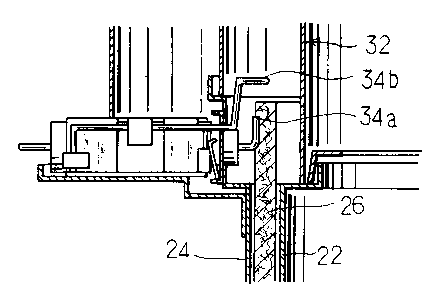
Referring now to Figs. 14 and 15, still another
modification of the discharge electrode means is illustrated. In
the illustrated modification, an outer cylindrical member 24 and
and inner cylindrical member 22 are formed so as to be different
in height of an upper end thereof from each other. One of the
outer and inner cylindrical members of which the upper end has a
larger height is mounted thereon with a first discharge electrode
34a of a discharge electrode means 34 through an insulator 76.
In the modification, the outer cylindrical member 24 is formed so
as to upwardly extend at the upper end thereof beyond the inner
cylindrical member 22.
More particularly, the first discharge electrode 34a of
the discharge electrode means 34 is mounted through an insulator
76 on an upper edge portion 84 of the outer cylindrical member 24
X114455
-17-
of a wick receiving cylinder structure 20. The first discharge
electrode 34a is arranged so as to extend toward a wick 26.
Also, the first discharge electrode 34a is vertically bent at a
distal end portion thereof, resulting in being formed with a
vertically extending parallel section 96 arranged in parallel to
the wick 26 when it is raised to a combustion position. The
discharge electrode means 34 also includes a second discharge
electrode 34b mounted on the outer cylindrical member 24 in
proximity to the first discharge electrode 34a. The second
discharge electrode 34b is likewise arranged so as to extend
toward the wick 26. Also, the second discharge electrode 34b is
bent at a distal end thereof, to thereby be formed with a
vertically extending parallel section 98 arranged in parallel to
the wick 26 when it is raised to a combustion position, as well
as in parallel to the vertically extending parallel section 96 of
the first discharge electrode 34a. In the illustrated
modification, the parallel sections 96 and 98 are formed so as to
upwardly extend. However, they may be arranged so as to
downwardly extend.
At least one of the parallel sections 96 and 98 of the
first and second discharge electrodes 34a and 34b is preferably
arranged so as to be contacted with the wick 26 or positioned
therein. Also, the parallel sections are preferably upwardly
enlarged or spread.
Reference numeral 100 designates a guard which is formed
so as to upwardly extend beyond the first and second discharge
electrodes 34a and 34b. The guard 100, when the discharge
electrode means 34 is disposed between the outer cylindrical
member 24 and the wick 26, is arranged inside the wick 26. In
this instance, the guard 100 is inside an inner cylinder 102 of a
combustion cylinder construction. Whereas, it is arranged
between the outer cylindrical member 24 and the wick 26 when the
discharge electrode means is disposed inside the wick 26. In
this instance, the guard 100 is arranged outside an outer
cylinder 104 of the combustion cylinder construction 32. The
guard 100 is conveniently made of a punched plate. The guard 100
21~44~5
-18-
serves as a protective means for preventing a human body such as
a hand or the like from touching the discharge electrode means 34
by mistake during cleaning of the ignition device or the like.
As described above, the ignition device of the
illustrated modification is so constructed that the vertically
extending parallel sections 96 and 98 of the discharge electrodes
34a and 34b each are arranged so as to be contacted with or
positioned in the wick. Such construction ensures positive
ignition of the wick. Also, arrangement of the guard 100
effectively prevents a human body from being shocked due to touch
with the discharge electrode means.
While a preferred embodiment of the invention has been
described with a certain degree of particularity with reference
to the drawing, obvious modifications and variations are possible
in light of the above teachings. It is therefore to be
understood that within the scope of the appended claims, the
invention may be practiced otherwise than as specifically
described.