Note: Descriptions are shown in the official language in which they were submitted.
211~770
VEHICLE CRASH CUSHION
BACKGROUND OF THE INVENTION
This invention relates to a vehicle crash
cushion for decelerating a vehicle that has left a
roadway and is moving toward a wall.
Young U.S. Patent 3,672,657 (assigned to the
assignee of the present invention) discloses a vehicle
crash cushion of the general type defined above. The
Young system includes an array of parallel diaphragms
with water-filled energy absorbing elements between the
diaphragms. The outermost diaphragms are arranged tG,
overlap, and the entire assembly is mounted to slide on
slide plates perpendicular or adjacent to a wall. An
impacting vehicle will move the outermost diaphragms
toward the wall, thereby accelerating water in the
energy absorbing elements. In this way, the severity
of the impact between the vehicle and the wall is
substantially reduced.
The Young crash cushion has shown itself to
be quite effective in actual use. In one installation
the Young crash cushion was placed on a wall at a
freeway turn in Detroit. Over ten years of practical
experience have shown a substantial reduction in
serious injuries and fatalities.
Nevertheless, the Young crash cushion is not
without drawbacks, primarily with respect to the level
of maintenance required to maintain the crash cushion
~lli770
- 2 -
in an operational condition. It has been found that
there is a tendency for the outermost diaphragms not to
return to the original position after an impact. In
some applications this may require that an entire
freeway be shut down while the outer diaphragms are
pulled back to the operational position. In practice
there is a tendency to delay such maintenance, and the
diaphragms themselves are more susceptible to damage if
hit by a second impact at a time when they have not
recovered properly from the first. Furthermore, the
Young crash cushion includes a number of interior
diaphragms which are susceptible to damage in a severe
impact. Certain elements are formed of wood, which are
susceptible to water damage and rotting, and debris
such as sand and litter tends to be trapped within the
system. It is difficult to remove this debris, and
excessive sand can build up inside the unit and
interfere with the operation of the crash cushion.
The present invention is directed to an
improved vehicle crash cushion which is less
susceptible to the maintenance problems of the Young
crash cushion described above.
SU~ARY OF THE INVENTION
According to this invention, a vehicle crash
cushion is provided for decelerating a vehicle that has
left a roadway and is moving toward a wall. The
barrier of this invention comprises a plurality of
panels positioned to overlap one another partially
along an anticipated impact direction. A mechanical
linkage is coupled to the panels to suspend the panels
above grade adjacent to the wall such that the panels
are oriented generally parallel to the wall, and the
panels are movable toward the wall in an impact. A
plurality of energy absorbing elements are positioned
211'177~
adjacent to the panels between the panels and the wall
and are suspended above grade at least in part by the
linkage, such that movement of the panels toward the
wall deforms the energy absorbing elements, thereby
retarding movement of the panels.
BRIEF DESCRIPTION OF THE DRAWINGS
FIG. 1 is an elevational view of a preferred
embodiment of the crash cushion of this invention
adjacent a wall.
FIG. 2 is a plan view taken along line 2-2 of
FIG. 1.
FIG. 3 is an end view taken along line 3-3 of
FIG. 1.
FIG. 4 is an exploded perspective view of one
of the modular units of the crash cushion of FIG. 1.
FIG. 5 is an exploded view of one of the
panels of FIG.l, with associated hardware.
FIG. 6 is a rear view of the panel of FIG. 5,
taken along line 6-6 of FIG. 5.
FIG. 7 is a perspective view in partial cut-
away of one of the clusters of energy absorbing
elements of the crash cushion of FIG. 1.
FIG. 8 is a top view of the cluster of energy
absorbing elements of FIG. 7.
DETAILED DESCRIPTION OF THE PRESENTLY
PREFERRED EMBODIMENTS
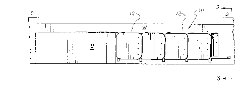
Turning now to the drawings, Figures 1-3 show
overall views of a crash cushion 10 which incorporates
a presently preferred embodiment of this invention.
This crash cushion 10 is mounted alongside a wall W
positioned adjacent to a roadway R. In this example
vehicles that travel along the roadway move in the
direction of the arrow A, which is therefore generally
211~770
oriented in the anticipated direction of impact of a
vehicle against the cushion 10. Though the wall W is
shown as a retaining wall, it should be understood that
the term "wall" is used broadly in this specification
and the following claims to cover longitudinally
extending fixed obstacles such as walls of various
heights, as well as bridge piers, medians and the like.
A rigid deflecting wedge D prevents impacting vehicles
from striking the forward end of the crash cushion 10.
As generally shown in Figure 2, the
cushion 10 includes an array of panels 12 arranged side
by side in overlapping configuration spaced from and
generally parallel to the wall W. Clusters of energy
absorbing elements 14 are interposed between the
panels 12 and the wall W, and the panels 12 are
suspended in place above the level of the roadway R by
a linkage 16 (Figure 3). The following paragraphs will
describe each of these elements of the crash cushion 10
in detail, before turning to a discussion of the
operation of the crash cushion 10.
As best shown in Figures 3 and 4, the
linkage 16 includes a mounting bracket 18 which in use
is mounted directly to the wall W. The mounting
bracket 18 in this embodiment defines a ledge 20 that
extends generally horizontally away from the wall W and
supports the energy absorbing elements 14. The
bracket 18 also defines a pivot axis 22 and cable
anchors 24, 26. An attachment plate 28 extends
partially over the width of the bracket 18, parallel to
the wall W. In use, the bracket 18 is rigidly secured
to the wall W, as for example with threaded fasteners
19 .
The energy absorbing elements 14 in this
embodiment are shaped as elastomeric tubes 30. Each
cluster of energy absorbing elements 14 in this embodi-
211~77~
-- 5
ment includes eleven of the tubes 30, and adjacent ones
of the tubes 30 are secured together by bolts 32
(Figure 7). Additionally, one (and only one) of the
tubes 30 is bolted to the attachment plate 28 by
bolts 34 (Figure 4). As explained below, this
attachment arrangement provides advantages in
operation. The two tubes 30 positioned closest to the
panels 12 are provided with protruding elements 36 such
as flat head bolts intended to provide low friction
sliding contact between the tubes 30 and the panels 12.
As best shown in Figure 3 and 4, the
linkage 16 also includes supporting struts 38. Each
strut 38 has a lower end that is pivotably mounted to
the respective pivot axis 22 and an upper end that is
pivotably mounted to a respective strut bracket 40.
Each strut bracket 40 additionally defines a pair of
cable attachment points 42 as shown in Figure 4.
The linkage 16 is stabilized by suspension
cables 44 and longitudinally extending cables 46
(Figures 2 and 4). The suspension cables 44 are
positioned almost in the plane of rotation of the
struts 38 as shown in Figure 2, and are anchored at one
end to the cable anchor 24 of the respective bracket 18
and at the other end to the strut bracket 40 of the
respective panel 12 (Figure 4). The suspension
cables 44 have a fixed length, and thereby limit the
maximum rotational movement of the struts 38 away from
the wall W. The longitudinally extending cables 46
extend between the cable anchor 26 and the cable
attachment point 42 of the respective bracket 18 and
strut bracket 40, respectively. The longitudinally
extending cables 46 are provided to prevent the
struts 38 and therefore the panels 12 from moving
excessively along the direction of the arrow A when a
vehicle impacts the cushion 10.
211~770
-- 6
Adjacent panels 12 are interconnected by slip
joints 48, as best shown in Figure 5. Each of the slip
joints is rigidly secured at one edge via threaded
fasteners 49 to the respective panel 12 and strut
bracket 40. Each of the slip joints 48 also defines an
array of slots 50. Fasteners 52 pass through the
slots 50 and are secured to the next adjacent panel 12.
Preferably, spacers are provided to prevent the
fasteners 52 from being tightened to such an extent as
to create excessive friction between the fasteners 52
and the slip joint 48. In this way, relatively free
sliding movement is allowed between adjacent panels 12.
When the cushion 10 is mounted to a wall W as
shown in Figure 3, the linkage 16 suspends the
panels 12 and the energy absorbing elements 14 above
grade. Note that in this example each of the struts 38
is oriented in its rest position at an angle of about
33 degrees with respect to the vertical. The lowermost
edges of the panels 12 are situated at least five
inches above grade, and the lowermost edges of the
energy absorbing elements 14 are situated about ten
inches above grade.
In the event of an impact of a vehicle
against the cushion 10, the force of the impact will
cause the panels 12 to move toward the wall W. This
motion is accommodated by rotation of the struts 38,
flexing of the suspension cables 44, and sliding of the
slip joints 48. As the panels 12 move toward the
wall W the energy absorbing elements 14 are elastically
deformed between the wall W and the panels 12. In this
example the energy absorbing elements 14 have an
outside diameter of six inches and a wall thickness of
about 1/2 of an inch. These thick-wall tubes provide
substantial resistance to deformation, thereby
generating a decelerating force tending to retard move-
211~770
ment of the panels 12 toward the wall W, and thereby to
decelerate an impacting vehicle.
During an impact the struts 38 lift the
panels 12 as the panels 12 approach the wall W. The
protruding elements 36 slide along the back side of the
panels 12 to facilitate this action. If desired, this
portion of the panels 12 can be covered with a suitable
low friction material such as a sheet metal plate 37
for example (Figure 6). Movement of the panels 12
upwardly is believed to enhance the ability of the
cushion 10 to decelerate an impacting vehicle while
reducing any tendency of the vehicle, to move upwardly
over the cushion 10.
The attachment system described above allows
the tubes 30 to be elastically deformed without damage
to the tubes 30. In particular, since only one of the
tubes 30 is bolted to the bracket 18, the tubes 30 can
freely increase in length (measured parallel to the
wall W) as they are compressed in depth (measured
perpendicular to the wall W). This movement would be
impeded and the tubes 30 might be damaged if multiple
ones of the tubes 30 of any given cluster were rigidly
secured to the bracket 18.
The cushion 10 has been designed to be self-
restoring for many impacts. As explained above, an
impacting vehicle moves the panels 12 toward the
wall W, thereby deforming the tubes 30. After the
vehicle has moved away from the cushion 10 the
resilience of the tubes will cause the panels 12 to
move downwardly and outwardly back to the original
position. The slip joints 48 facilitate this movement
by maintaining the friction between adjacent panels 12
at an acceptable level. The linkage 16 further
facilitates this restoring action, because the
panels 12 move downwardly as they move outwardly.
211~770
The cushion 10 has been designed to minimize
installation and maintenance problems. For example,
the bracket 18 minimizes the number of attachments
required to the wall W. This allows substantial
portions of the cushion 10 to be preassembled and then
quickly and efficiently mounted on the wall W. Further-
more, all of the elements of the cushion 10 have been
designed for reuse. As explained above, the cushion 10
will automatically restore itself to its initial posi-
tion after an impact, and the energy absorbing ele-
ments 14 are not damaged in a typical impact. Because
the panels 12 and the energy absorbing elements 14 are
suspended above grade by the linkage 16, free movement
of the panels 12 back to their original position is not
impeded by friction with the ground or low lying
obstacles on the ground.
The fact that the panels 12 and the energy
absorbing elements 14 are suspended above grade further
simplifies maintenance. Because the panels 12 are not
in contact with the ground there is reduced water
damage. Also, debris such as litter, sand and the like
which enters at the top of the cushion 10 tends to fall
down through the elements of the cushion 10 to the
underlying ground, where it can readily be swept away
without obstruction. Interior diaphragm panels have
been eliminated, and are therefore not subject to
damage. The elastomeric tubes 30 are rugged, and not
easily damaged in an impact. The weight of the panel
acts to increase the efficiency of energy absorption,
because the panel is actually raised during an impact.
Simply by way of example the following
details of construction are provided in order to define
the presently preferred embodiment of this invention
clearly. It of course should be understood that these
details of construction are provided only by way of
211i77U
example, and that they are not intended to limit the
scope of this invention.
By way of example, the panels 12 can be
formed of 3/4 inch plywood that has been wrapped with
fiberglass monofilament in two orthogonal orientations
and then covered with chopped fiberglass and resin to a
final thickness of approximately 1-1/4 inches. The
panels can for example be 32 inches in width and 33
inches in height. The tubes 30 can for example be
formed of a material with the physical characteristics
set out in Table 1.
TABLE 1
Preferred Material Characteristics of Tube 30
Item Approximate Values Test Method
Hardness 80 Shore A Durometer ASTM D-2240
(+/-3)
Tensile Strength 3544 psi (m;nlmllm) ASTM D-412
Elongation 434~ (minimum) ASTM D-412
Modulus at
100~ Elongation 615 psi (+10~-5~)
200~ Elongation 1,678 psi (10%-5~)
300~ Elongation 2,668 psi (10~-5~)
Compression Set 25~ (maximum) ASTM D-395
22 hrs. at 158 Deg. F Method B
Tear Strength 349 lb/in. (mlnlml~m) ASTM D-624
Die C
Specific Gravity 1.20 (+/-2~)
A suitable material can be obtained from R.M.-Holtz,
Inc., Lodi, CA as R8487 rubber. The suspension
cables 44 can for example be formed of 1/4 inch
galvanized wire rope, and the longitudinally extending
cables 46 can be formed of 3/8 inch galvanized wire
rope. The slip joint 48 can be formed of 1/8 inch
thick flat steel bar with slots 2-1/2 inches in length.
211~77û
- 10 -
The struts 38 can be formed of 1-1/4 inch steel pipe
(Schedule 80). The bracket 80 can be welded from suit-
able steel angles and bars.
Of course, a wide range of changes and
modifications can be made to the preferred embodiment
described above. This embodiment provides important
advantages in that it is self-restoring. However, if
this is not essential for a particular application
other types of energy absorbing elements including
sacrificial energy absorbing elements can be used. The
panels described above are preferred, but other rigid
panels such as Thrie beams can be used if desired. The
lifting linkage described above provides several
advantages, but other types of suspending linkages can
be substituted (including non-lifting linkages and
scissors linkages for example) to suspend the panel and
the energy absorbing elements above ground level. The
number and angular orientation of the longitudinally
extending cables can be modified, as long as the cables
extend longitudinally to some extent to resist movement
of the panels parallel to the wall.
It is therefore intended that the foregoing
detailed description be regarded as illustrative rather
than limiting, and that it be understood that it is the
following claims, including all equivalents, which are
intended to define the scope of this invention.
-- 10