Language selection

Search

Patent 2114820 Summary

Third-party information liability

Some of the information on this Web page has been provided by external sources. The Government of Canada is not responsible for the accuracy, reliability or currency of the information supplied by external sources. Users wishing to rely upon this information should consult directly with the source of the information. Content provided by external sources is not subject to official languages, privacy and accessibility requirements.

Claims and Abstract availability

Any discrepancies in the text and image of the Claims and Abstract are due to differing posting times. Text of the Claims and Abstract are posted:

  • At the time the application is open to public inspection;
  • At the time of issue of the patent (grant).
(12) Patent: (11) CA 2114820
(54) English Title: TORQUE LIMITING DRIVE AND PROGRAMMER/TIMER EMPLOYING SAME
(54) French Title: ENTRAINEMENT LIMITEUR DE COUPLE ET PROGRAMMATEUR/TEMPORISATEUR L'EMPLOYANT
Status: Expired and beyond the Period of Reversal
Bibliographic Data
(51) International Patent Classification (IPC):
  • F16D 7/02 (2006.01)
  • G04C 23/08 (2006.01)
  • G04C 23/10 (2006.01)
  • H01H 3/58 (2006.01)
  • H01H 43/10 (2006.01)
(72) Inventors :
  • MAHON, JOSEPH J. (United States of America)
  • AIGNER, ROBERT K. (United States of America)
(73) Owners :
  • EATON CORPORATION
(71) Applicants :
  • EATON CORPORATION (United States of America)
(74) Agent: BORDEN LADNER GERVAIS LLP
(74) Associate agent:
(45) Issued: 1999-09-28
(22) Filed Date: 1994-02-02
(41) Open to Public Inspection: 1994-08-05
Examination requested: 1995-11-15
Availability of licence: N/A
Dedicated to the Public: N/A
(25) Language of filing: English

Patent Cooperation Treaty (PCT): No

(30) Application Priority Data:
Application No. Country/Territory Date
013,501 (United States of America) 1993-02-04

Abstracts

English Abstract


A torque limiting drive and programmer/timer using same. A motor drives
a driving member which has drive lugs engaging the central web of a
plural-armed wave spring. The wave spring arms frictionally engaged radially
oppositely facing annular friction surfaces on a driven member, which in a
programmer/timer is the program cam, which upon rotation of the cam is
operative for sequentially actuating electrical switches. User rotation of the
cam when the motor is not operative allows the wave spring arms to slip
against the annular friction surfaces permitting the user to position the cam
as
desired.


Claims

Note: Claims are shown in the official language in which they were submitted.

6
CLAIMS:
1. A torque limiting drive assembly adapted for receiving a shaft comprising:
(a) a rotatable driving clutch member adapted for connection to a rotating
source of power having thereon first axially engageable surfaces for rotary
driving
connection therewith;
(b) a driven clutch member having a first annular friction surface disposed on
an inner periphery thereof and a second annular friction surface disposed
concentrically
within, spaced radially from, and facing said first annular surface;
(c) a spring member assembled onto said driven clutch member and having
outer portions thereof frictionally engaging said first annular friction
surface and inner
portions thereof engaging said second annular friction surface, said outer and
inner
portions disposed in circumferentially spaced alternating arrangement, said
driving
member, said driven member and said spring member forming an assembly adapted
for
receiving a shaft, whereupon application of torque above a predetermined level
to either of
said driving or driven member causes rotary movement of said spring member
with respect
to said first and second friction surfaces.
2. The drive assembly defined in claim 1, wherein said first and second
annular
friction surfaces have a generally cylindrical configuration.
3. The drive assembly defined in claim 1, wherein said spring member has a
central hub, said axially engageable driving surfaces and a radially extending
web, said
inner and outer portions extending in a circumferential direction from said
web.

7
4. A programmer/timer comprising:
(a) base means;
(b) cam means disposed for rotary movement on said base means and
including said first and second oppositely facing annular friction
surfaces;
(c) cam follower means responsive to said rotary movement of said
cam means for movement on said base means;
(d) switch means. mounted on said base means and responsive to said
movement of said cam follower for opening and closing a set of
electrical contacts;
(e) wave spring means mounted on said cam means having certain
distinct portions thereof frictionally engaging said first and second
friction surfaces, said wave spring means having certain other
portions defining torque transmitting surfaces;
(f) a driving member disposed for rotary movement on said base
means having certain portions thereof engaging said torque
transmitting surfaces of said wave spring means for transmitting
torque thereto; and,
(g) motorized advance means drivingly connected to said driving
member and operative to effect said rotary movement thereof,
wherein upon application of sufficient torque to said cam means by
the user, said wave spring means is effective to slip against said
first and second friction surfaces permitting relative rotation
between said cam means and said driving member.
5. The programmer/timer defined in claim 4, wherein said driving member
comprises a gear and said certain surface portions comprise a plurality of
axially-extending lugs.
6. The programmer/timer defined in claim 4, wherein said wave spring
comprises a member having a central radial web with said certain other

8
portions formed therein and with a plurality of wave portions extending
axially from said web.
7. The programmer/timer defined in claim 4, wherein said cam means
includes shaft means having torque input surfaces therein adapted for
engagement by a user torque input member.
8. The programmer/timer defined in claim 4, wherein said base means
includes a shaft mounted thereon with said driving member journalled for
rotation on said shaft.
9. The programmer/timer defined in claim 4, wherein said base means
includes a shaft mounted thereon with said driving member and said cam
means journalled for rotation on said shaft.

Description

Note: Descriptions are shown in the official language in which they were submitted.


21i~~~~
1 92-CON-529 (APl
TORQUE LIMITING DRIVE AND
PROGRAMMER/TIMER EMPLOYING SAME
BACKGROUND OF THE INVENTION
The present invention relates to torque limiting drives, or friction clutches
as they are sometimes called, of the type permitting slippage at torques above
a
predetermined level or value. Drivers of this type find application in timing
mechanisms and programmer/timers for appliances. Devices of this type, and
particularly programmerltimers for appliances typically utilize a small, sub-
fractional horsepower timing motor driving an advance mechanism for
advancing a rotating cam which sequentially actuates various electrical
switches
for effecting the various functional operations for the appliance service
cycle or
program.
Where an appliance is controlled by a timing motor advancing a rotary
cam for sequentially actuating a plurality of switches, it is common practice
to
arrange the rotary cam such that it can be turned manually by the appliance
user to a desired position representing a portion of the program prior to
energizing the timing motor for beginning the appliance program cycle. Such an
arrangement requires that the cam drum be rotated or advanced by the user
against the friction forces of the cam followers for all of the switches and
against the forces of the timer advancing mechanism or require that the
advancing mechanism be released to permit such cam rotation by the user.
Heretofore, user rotation for program selection by rotating the of the
appliance programmer/timer has resulted in difficulty in designing the program
cam advance mechanism and the cam followers for the switches to permit such
rotation without undue torque being applied by the user or without causing
damage to the advance mechanism in the event of reverse rotation of the cam.
Thus, it has been desired to provide a way or means of permitting the user to
rotate the program cam of a timer motor advanced switching cam in an
appliance programmer/timer without causing damage to the advance mechanism
or presenting difficulties in the user manually applying the torque necessary
to
advance the cam against the friction forces of the switches.

. zm4s~~
2 92-CON-529 (APJ
SUMMARY OF THE INVENTION
The present invention provides a torque limiting friction drive or clutch
mechanism having a driven member with oppositely facing annularly disposed
friction surfaces arranged generally concentrically. A wave spring member
frictionally engages both of the oppositely facing annular friction surfaces;
and,
driving lugs on a driving member axially engage the wave spring for driving
the
driven member upon application of power to the driving member. Upon user
application of torque to the driven member when the drive is inoperative, the
wave spring permits slippage on the friction surfaces to permit relative
rotation
between the driving and driven member. The wave spring of the present
invention is assembled onto the driven member to perform a subassembly which
facilitates assembly of the pleated drive unit by requiring only axial
engagement
of the driving member lugs with the wave spring.
The programmer/timer of the present invention employs the torque
limiting drive between the user torque input, which is to the driven member,
to
permit rotation of the driven member as the cam for actuating the function
switches with respect to the driving member connected to a timer motor driven
advance mechanism.
BRIEF DESCRIPTION OF THE DRAWINGS
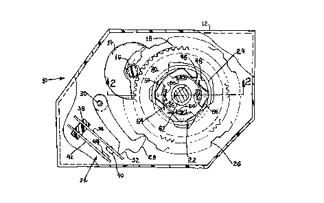
FIG. 1 is a plan view of a programmer/timer employing the present
invention with portions of the casing removed;
FIG. 2 is a portion of a section view taken along section indicating lines
2-2 of FIG. 1;
FIG. 3 is a plan view of the wave spring employed in the embodiment of
FIG. 1;
FIG. 4 is a bottom view of the wave spring of FIG. 3; and,
FIG. 5 is a section view similar to FIG. 2 of an alternate embodiment of
the invention.

211820
3 92-CON-529 (APJ
DETAILED DESCRIPTION
Referring to FIG. 1 and FIG. 2, a programmer/timer employing the present
invention is indicated generally at 10 and has a housing or base means 12 upon
which is mounted a timing motor 14 which is operatively connected to the drive
pinion 16, which engages peripheral teeth 18 provided about driving member
20.
Driving member 20 is connected by a torque limiting drive or friction
clutch indicated generally at 22 to a driven member 24 which, in the
embodiment of FIG. 1, has a cam track 26 formed about the periphery thereof,
and which is engaged by a cam follower 28 pivotally mounted on base 12 by
shaft 30. Cam follower 28 has an actuator portion 32 which contacts one
blade 36 of a switch indicated generally at 34, which has blade 36 extending
from mounting block 38 provided on the base 12 and which has one electrical
contact 40 mounted thereon. A second blade 42 of switch 34 extends from
block 38 and has a second electrical contact 42 mounted thereon which
contact 42 is opened and closed against contact 40 as cam follower 28 moves
in response to the rotation of cam track 26.
Referring to FIGS. 1 through 4, the torque limiting drive 22 comprises
radially inner and radially outer oppositely facing annular surfaces 46, 48
provided on the driven member 24, and which are disposed concentrically
thereon.
A spring member indicated generally at 50 is received on and frictionally
engages the driven member 26 to form a subassembly. Spring 50 has a central
radially-extending web 52 with oppositely disposed wave portions 54, 56
formed integrally therewith and extending generally at right angles to the
central
web 52, with the wave portions having alternating portions thereof
frictionally
engaging the inner and outer annular surfaces 46,48. The central web 52 of
the spring 50 has a plurality of torque transmitting surfaces in the form of
cut-
outs 58 disposed about the circumference of the central web 52. The driving

21~.482~
4 92-CON-529 (APJ
In the presently preferred practice, the driving member 20 and driven
member 24 are journalled for rotation about shaft 62, which is mounted on the
base means 12, and extends through a central opening 64 provided in the web
52 of spring 50.
A user torque input surface is provided on the driven member 26 in the
form of a stub shaft 66 extending outwardly through an aperture 68 formed in
the base 12 with a flat surface 70 provided on the stub shaft and adapted for
receiving a knob thereon. Thus, upon user input torque applied to the flat
surface 70, the driven member 26 rotates with respect to the wave spring
portions 54,56 which slide frictionally along the surfaces 46,48 of the
driving
member, thereby permitting relative rotation of the driven member 24 with
respect to the driving member 20 for positioning the cam 26 in the desired
position.
Referring to FIG. 5, an alternate embodiment of the invention is indicated
generally at 100 and employs a housing 102 with timing motor 14' mounted
therein driving pinion 16' which engages peripheral teeth 18' on driving
member
20', which is identical to the member 20 in the embodiment of FIG. 2. Driving
member 20' is journalled for free rotation about the shaft 62' mounted in
blind
bore 112 formed on the wall of the base 102. Shaft 62' extends outwardly
through bore 110 formed in the opposite ball of the base 102, with exterior
torque transmitting surfaces 114 provided thereon for user torque application
to
shaft 62'.
Shaft 62' has a flat 104 provided thereon which is engaged by the inner
periphery 106 of a driven member 24' which is identical to the member 24 of
the embodiment of FIG. 2, except for the flat surface 106 which engages shaft
62' flat surface 104. Driven member 24' has assembled therein a wave spring
indicated generally at 50' which is otherwise identical to the wave spring 50
of
the embodiment FIG. 2, and engages the concentric annular friction surfaces
46',48' on driven member 26' in the same manner as in the FIG. 4
embodiment.
The wave spring 50' has recesses formed therein which are engaged in
an axial direction by the lugs 60' provided on the driving member 20' in the

2.14820
92-CON-529 /APJ
same manner as described in the embodiment of FIG. 2. The embodiment of
FIG. 5 thus utilizes the flat surface 106 of shaft 62' to transmit user
applied
torque to the shaft to the driven member surface 104' to effect relative
rotation
between driven member 24' and driving member 20' for positioning of the cam
5 track 26' by the user when the motor drive is not in operation by frictional
slippage of the wave spring with respect to the annular friction surfaces of
the
member 24'.
The present invention thus provides a simple, low-cost, easily assembled
torque limiting drive or friction clutch which has particular application for
advance mechanisms such as employed programmer/timers for appliances.
Although the invention has hereinabove been described here with respect
to the embodiments illustrated in the drawings, it will be understood that the
invention is capable of modification and variation by those skilled in the
art, and
is limited only by the scope of the following claims.

Representative Drawing
A single figure which represents the drawing illustrating the invention.
Administrative Status

2024-08-01:As part of the Next Generation Patents (NGP) transition, the Canadian Patents Database (CPD) now contains a more detailed Event History, which replicates the Event Log of our new back-office solution.

Please note that "Inactive:" events refers to events no longer in use in our new back-office solution.

For a clearer understanding of the status of the application/patent presented on this page, the site Disclaimer , as well as the definitions for Patent , Event History , Maintenance Fee  and Payment History  should be consulted.

Event History

Description Date
Inactive: IPC from MCD 2006-03-11
Time Limit for Reversal Expired 2002-02-04
Letter Sent 2001-02-02
Grant by Issuance 1999-09-28
Inactive: Cover page published 1999-09-27
Pre-grant 1999-07-05
Inactive: Final fee received 1999-07-05
Notice of Allowance is Issued 1999-03-15
Letter Sent 1999-03-15
Notice of Allowance is Issued 1999-03-15
Inactive: Application prosecuted on TS as of Log entry date 1999-03-10
Inactive: Status info is complete as of Log entry date 1999-03-10
Inactive: IPC assigned 1999-03-08
Inactive: First IPC assigned 1999-03-08
Inactive: IPC removed 1999-03-05
Inactive: First IPC assigned 1999-03-05
Inactive: IPC assigned 1999-03-05
Inactive: IPC removed 1999-03-05
Inactive: IPC assigned 1999-03-05
Inactive: Approved for allowance (AFA) 1999-03-04
All Requirements for Examination Determined Compliant 1995-11-15
Request for Examination Requirements Determined Compliant 1995-11-15
Application Published (Open to Public Inspection) 1994-08-05

Abandonment History

There is no abandonment history.

Maintenance Fee

The last payment was received on 1998-12-18

Note : If the full payment has not been received on or before the date indicated, a further fee may be required which may be one of the following

  • the reinstatement fee;
  • the late payment fee; or
  • additional fee to reverse deemed expiry.

Please refer to the CIPO Patent Fees web page to see all current fee amounts.

Fee History

Fee Type Anniversary Year Due Date Paid Date
MF (application, 4th anniv.) - standard 04 1998-02-02 1998-01-15
MF (application, 5th anniv.) - standard 05 1999-02-02 1998-12-18
Final fee - standard 1999-07-05
MF (patent, 6th anniv.) - standard 2000-02-02 1999-12-10
Owners on Record

Note: Records showing the ownership history in alphabetical order.

Current Owners on Record
EATON CORPORATION
Past Owners on Record
JOSEPH J. MAHON
ROBERT K. AIGNER
Past Owners that do not appear in the "Owners on Record" listing will appear in other documentation within the application.
Documents

To view selected files, please enter reCAPTCHA code :


To view images, click a link in the Document Description column. To download the documents, select one or more checkboxes in the first column and then click the "Download Selected in PDF format (Zip Archive)" or the "Download Selected as Single PDF" button.

List of published and non-published patent-specific documents on the CPD .

If you have any difficulty accessing content, you can call the Client Service Centre at 1-866-997-1936 or send them an e-mail at CIPO Client Service Centre.


Document
Description 
Date
(yyyy-mm-dd) 
Number of pages   Size of Image (KB) 
Claims 1999-02-24 3 93
Cover Page 1995-06-09 1 43
Abstract 1995-06-09 1 35
Claims 1995-06-09 3 127
Drawings 1995-06-09 2 72
Description 1995-06-09 5 251
Cover Page 1999-09-21 1 42
Representative drawing 1998-08-19 1 21
Representative drawing 1999-09-21 1 15
Commissioner's Notice - Application Found Allowable 1999-03-15 1 164
Maintenance Fee Notice 2001-03-05 1 176
Correspondence 1999-07-05 1 29
Fees 1996-12-16 1 72
Fees 1995-12-21 1 73
Prosecution correspondence 1994-02-02 3 81
Prosecution correspondence 1995-11-15 1 24
Courtesy - Office Letter 1995-12-05 1 37
Prosecution correspondence 1999-01-13 2 61
Examiner Requisition 1998-07-14 2 52