Note: Descriptions are shown in the official language in which they were submitted.
21~.~8~~
1
This invention relates to a new and improved shower control valve
assembly.
BACKGROUND OF THE INVENTION
In the construction of residential and commercial buildings it is common
to have back-to-back bathrooms wherein the hot and cold water supply pipes
service
shower and tub units on opposite sides of the wall. Prior art shower control
valves
often have the cold water inlet on one side and the hot water inlet on the
other side.
As the two supply pipes in the wall are normally side-by-side, it is necessary
to
provide an awkward cross-over arrangement for one of the shower units. Later
inventions provided shower control valve assemblies that utilise a casing
having two
inlets and a replaceable cartridge unit which can be adjusted in a relatively
simple
manner at the time of installation so that it is entirely optional as to which
of the inlets
is connected to the hot water supply pipe and which is connected to the cold
water
pipe. Commonly assigned Canadian Patent No. 1,050,853 of March 20, 1979
discloses just such an arrangement. The valve assembly of that patent is
pressure
balanced, with a single handle to control the temperature and the pressure of
the water
issuing from the shower. The casing of the patented valve assembly included a
single
outlet leading to the shower, water for the tub flowing through a separate
spout having
a diverter valve associated therewith.
The trend in pressure balanced valve assemblies has been towards single
handle control valves which are also adapted to control the flow of water to a
tub as
2
well as to a shower. U.S. Patents 4,681,140; 4,901,750; and 4,905,732 all
teach
single handle pressure, temperature and/or volume balanced mixing valves.
One of the problems associated with any water flow arrangement is that
of water hammer, generated noise which is frequently experienced in pressure
sensing
mixing valves when they are installed in line with quick closing faucets or
diverter
valves. Other problems involve cross flow between the hot and cold water
supply
lines, back flow in either or both of the supply lines, and wear of the rubber
seal that
contacts the mixing disc of the valve.
Commonly assigned Canadian Patent Application No. 2,076,924 filed
August 26, 1992 teaches a single handle pressure and temperature balancing
mixing
valve assembly that includes, among other features, a check valve at each of
the hot
and cold water inlets to prevent cross flow between the hot and cold water
supply
lines, to prevent back flow to either supply line, and to eliminate the
effects of water
hammer. Additionally, or optionally, the valve casing may include separate
outlets for
the tub and for the shower, with there being a built-in bypass or diverter
channel to
divert water from one outlet to the other and the entire valve cartridge may
be rotated
through 180° to reverse the hot and cold inlets.
Commonly assigned Canadian Patent Application No. 2,109,034 filed
October 21, 1993 provides an improvement to the aforementioned application by
having the mixing disc in constant contact with a pair of axially movable seat
members
and by having each seat member contact a fixed O-ring seal in the closed
position of
the valve disc. The O-ring is free from contact with any of the moving
components
~~~48~~
'- 3
of the valve per se. Sealing contact of the O-ring is made only at the valve
closing
position, thus reducing torque and eliminating wear. Each axially movable seat
member is made of a plastics material having a low friction property. The seat
members are held in contact with the mixing disc by water pressure only. A
circular
wave spring placed under a snap seal that holds the O-ring exerts enough force
to seal
the water at low supply pressures. The wave spring also takes up any slack due
to the
natural wear between the axially movable seat member and a cam surface on the
mixing disc.
Another area requiring improvement with such pressure balanced valves
is the diverter valve that is used to divert water from the tub faucet to the
shower
nozzle. The most common type of diverter involves a valve actuator positioned
in the
faucet itself, such that raising the actuator while water is flowing through
the faucet
will close the diverter valve and cause the water to be forced to the shower
nozzle.
If the user of the shower is already in the tub enclosure he or she will have
to bend
over to actuate the diverter, an inconvenience at the least. Also, such
diverter valves
are strictly of the "on/off' variety; they do not have the capability of any
volume,
pressure or temperature adjustment. If there is any failure of the diverter
valve it is
necessary to dismantle the faucet and the attendant valve structure to effect
repair, a
time consuming and possibly expensive proposition. There is therefore a need
for a
more-convenient, adjustable, and easily repaired diverter valve structure for
pressure
balanced valve installations.
2~~.~~~~
SU1VINIARY O» T» INVENTION
The present invention provides an improved diverter valve structure
for combination tub and shower valve installations, the diverter valve
structure of the
invention being particularly effective with single handle pressure balanced
mixing valve
installations. In such installations the valve is usually mounted on the wall
of the
tub/shower enclosure between the shower head and the tub faucet, at a height
convenient for most people. The diverter valve of the invention is
incorporated into
the casing of the mixing valve and includes an actuating rod projecting
outwardly from
the diverter valve below the mixing valve handle. The rod is reciprocable and
operates a counterweighted butterfly valve in the outlet passage of the valve.
While
water is flowing through the faucet the rod is pushed inwardly to move the
butterfly
valve into the stream of flowing water so that the force of the water quickly
moves the
butterfly valve to close the passage to the faucet. Water then is forced to
flow through
the diverter passage to the shower head. When the shower is turned off the
butterfly
valve will automatically rotate back to its open position under the influence
of the
counterweight provided on the downstream wing thereof.
The rod will have an attractive knob at the outer end thereof for ease of
manipulation and the rod will also be rotatable such that appropriately
contoured
mating housing and rod portions at the inner end thereof can throttle the
flowing water
and thus control the volume of water flowing to the shower head.
5
The housing or insert for the butterfly valve will be removable through the
front of the casing to effect easy replacement in the event of failure for any
reason.
This replacement feature is particularly effective when the mixing valve is of
the
replaceable cartridge variety, such as is disclosed in the aforementioned
Canadian
patent and patent applications.
Generally speaking therefore the present invention may be defined as
providing a diverter valve assembly for a shower control valve assembly having
a
casing with first and second water inlets, water outlet means leading to a tub
faucet,
and means within the casing for mixing water entering via the inlets and
feeding mixed
water to the outlet means. The outlet means is connected to a diverter passage
that
leads to a shower head. The diverter valve assembly includes a valve insert
positioned
within the outlet means, the insert including a valve seat and a rotatable
valve member.
A counterweight on one wing of the valve member biases the valve member to a
normally open position. A laterally extending reciprocable rod member has an
inner
end thereof adjacent the other wing of the valve member for contact with the
other
wing so as to rotate the valve member into the stream of water flowing in the
outlet
means and thus towards a closing position, the flowing water in the outlet
means
moving the valve member to its fully closed position. In the closed position
water is
prevented from flowing through the outlet means to the tub faucet and is
forced to flow
into the diverter passage towards the shower head. When the water is turned
off at
the mixing valve the valve member will rotate back to its fully open position
under the
influence of the counterweight on the one wing.
~~.~4~
'-' 6 _
BRIEF DESCRIPTION OF THE DRAWINGS
Figure 1 is an exploded view of a shower mixing valve illustrating the
main components of the invention.
Figure 2 is a front end view of a shower mixing valve incorporating the
present invention therein.
Figure 3 is a sectional view on a vertical plane of the casing with a mixing
cartridge installed therein.
Figure 3A is an enlarged partial sectional view of the valve section shown
in Figure 3 with the valve of this invention in the closed position.
Figure 3B is a partial sectional view of the valve section shown in Figure
3 with the valve of this invention in an intermediate position.
Figure 3C is a somewhat enlarged partial sectional exploded view of the
valve section of Figure 3A.
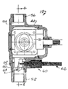
Figure 4 is a sectional view of the casing on the line 4-4 of Figure 3.
Figures 5 and 6 are front and side views respectively of the insert.
Figure 7 is a sectional view of the insert as taken on the line 7-7 of Figure
6.
Figure 8 is a sectional view of the insert as taken on the line 8-8 of Figure
5.
Figures 9, 10, 11 and 12 are top, bottom, side and end views respectively
of the butterfly valve used in this invention.
Figures 13 and 14 are sectional and end views respectively of the actuating
rod used in this invention.
~114~~~
DESCRIPTION OF THE PREFERRED EMBODI1VVIENT
Referring to Figure 1 there is shown an exploded assembly view of the
shower valve 10 of the present invention. A casing 12 is mounted in the wall
14 of
the shower and is connected to the hot and cold water pipes (not shown), one
being
connected to the casing on each side thereof. The casing is also connected to
outlet
conduits (not shown) which lead to the shower head and to the tub faucet. The
casing
12 has a central opening 16 which receives a mixing cartridge 18 such as those
described in the aforementioned Canadian patent and patent applications.
The cartridge 18 has a pinion shaft 20 extending therefrom and a cover
22, with sealing ring 24 interposed, is assembled to the casing 12 via machine
screws
26. An intermediate shaft 28 extends through the cover 22 and is attached to
the
pinion shaft 20 by a machine screw 30. An escutcheon plate 32 covers the
opening
in the shower wall and is attached to elongated bosses 34 on the cover 22 by
machine
screws 36. A control knob 38 is attached to the intermediate shaft 28 by a
machine
screw 40 and has a removable cover 42 to hide the screw 40 from view.
With reference to Figures 1, 2 and 3, the casing 12 is normally mounted
between the studs of a bathroom wall and, in the case of back-to-back
installations in
which there is a tub/shower installation on each side of the wall, the hot and
cold
water supplies indicated by the letters A and B may be interchanged. With this
apparatus it is simply a matter of positioning the cartridge in one of two
possible
orientations so as to permit the supply A to be either hot or cold with the
other supply
being the opposite temperature.
~~.~48~J
8
The casing 12 is best seen in Figures 3 and 4. The casing is preferably
cast from brass and has a generally cylindrical section 44 with the optionally
reversible
hot and cold water inlets 46 and 48 on opposite sides thereof. A mixed water
outlet
50 from the mixing chamber of the casing leads to a coupling 52 which in turn
will
be connected to a suitable conduit leading to the tub faucet (not shown). A
diverter
passage 54 is integrally cast into the casing, interconnecting the outlet 50
and an outlet
56 connectable to a suitable conduit leading to the shower head (not shown).
Normally, mixed water will flow to the tub via outlet 50 and coupling 52.
However,
when the shower is to be used the diverter valve 60 of the present invention,
positioned below the casing body 44, will be activated to prevent water
flowing
through the outlet 50 and thereby forcing it through the diverter passage 54
to the
shower outlet 56.
The diverter valve assembly 60 of the present invention includes several
components, namely insert means 62, a valve member 64 and an actuator rod
member
66. Each of these components as well as the assembly thereof and their
operation will
be described hereinbelow and with reference to Figures 3 to 14.
The insert means 62 is best seen in Figures 3A, 3C, and 5 to 8. The insert
means 62 is generally cylindrical in configuration, having a C-shaped wall
section 68
and upper and lower peripheral flanges 70,72 extending radially of the wall
68. The
wall 68 terminates at a straight wall section 74 and a plurality of
circumferentially
spaced arcuate projections 76 extend outwardly from the straight wall section
74. A
straight transverse flange 78 angles inwardly and downwardly at an angle "x"
within
the interior of the insert means 62 and then extends downwardly (Figure 8).
The
2~.~~~~~
9
lower edge 80 of the flange 78 is generally arcuate as seen best in Figure 7.
The
flange 78 and the opposite wall portion of the insert means define an outlet
passageway
82 leading to the coupling 52 for mixed water exiting the mixing chamber of
the
mixing valve.
At the bottom of the insert means 62 there is provided a valve seat 84, the
seat 84 being made up of two generally semi-circular portions 86 and 88. The
seat
portion 86 appears as a lip extending inwardly from the lower edge of a
portion of the
C-shaped wall section 68 while the seat 88 appears as an undercut below the
straight
wall 74 and the remainder of the C-shaped wall section 68.
An aperture 90 extends radially through the wall section 74 and has the
same diameter as the inner arcuate surface of the projections 76. The spaces
92
between adjacent projections 76 define channels, the use of which will become
apparent hereinafter. The flange 78 is also provided with an arcuate cutout
portion 94
in its lower edge 80 that is collinear with the aperture 90, while the flange
72 is
provided with an arcuate recess 95 in its upper edge as seen in Figure 5.
The valve member 64 is best seen in Figures 3, 3A, 3B, 3C and 9 to 12.
It is in the form of a circular disc or butterfly having a pair of semi-
circular wing
portions 96,98 leading away from a transverse journal section 100. The wing
portions
are offset from each other in the direction of water flow through the insert
means, with
the wing portion 96 being defined as the upstream wing and the wing portion 98
being
defined as the downstream wing. A transverse bore 102 extends through the
journal
section 100 and carries a shaft 101 (Figure 3C) receivable in the bores 103 at
the
Z~~4~~
bottom of the insert means 62 as seen in Figures 6 and 7 so as to rotatably
mount the
valve member in the insert means.
A lower strengthening portion 104 curves from the journal section to the
upstream wing 96, leaving a narrow lower peripheral lip 106 on the
undersurface of
5 that wing. The downstream wing 98 carries a D-shaped counterweight 108 that
extends away from the wing in a direction that can be considered as upstream
of the
valve member 64. The counterweight is located on the wing 98 so as to leave a
narrow upper peripheral lip 110 on the upper surface of that wing. The
counterweight
has an arcuate outer wall 112 and is provided with a generally semi-
cylindrical recess
10 114. The counterweight serves to bias the valve member 64 to a generally
vertical
orientation as seen in Figures 3 and 11 when there are no other forces
operating on the
valve member.
The actuator rod member 66 is best seen in Figures 3, 3A, 3B, 3C, 13 and
14. It includes an elongated cylindrical stem portion 116 with means (not
shown)
provided at the outer end 118 thereof for attachment thereto of a suitable
knob 119
which will facilitate reciprocation and rotation of the rod member 66. At the
inner end
thereof the rod member has a cruciform section 120 defined by right angle ribs
122
and a small diameter extension 124 that projects beyond the section 120. The
diameter
of the rod 66 is such as to provide a sliding fit in the aperture 90.
With reference to Figures 3A and 3C in particular it will be seen that the
casing 12 is provided with an enlarged boss 126 below the cylindrical section
44, the
boss having a central bore 128 extending therethrough. The bore 128
accommodates
11
the rod member 66 to provide a sliding fit therewith. Since the rod member 66
is
capable of rotation the bore 128 and the rod member 66 should be cylindrical
in
nature. Counterbores 130 and 132 open outwardly from the bore 128, the
counterbore
132 being internally threaded so as to receive a threaded retaining cap 134.
1'he cap
134 has an opening 136 through the end wall thereof through which the rod
member
66 can pass. An O-ring 138 is receivable in the counterbore 130 to sealingly
surround
the rod member 66. A washer member 140 abuts the shoulder between the
counterbores 130 and 132 to help retain the O-ring 138 in the counterbore 130
and to
act as a flat surface against which one end of a compression spring 142 can
bear. The
other end of the spring 142 bears against an annular flange 146 integrally
provided on
the rod member, the flange being slidably receivable within the cap 134. The
cap
defines a stop against which the flange 146 can abut when the spring 142 is
fully
expanded.
The operation of the diverter and volume control valve of the invention will
now be described with particular reference to Figures 3, 3A, and 3B. Figure 3
illustrates the normal rest position of the valve member 64 and the rod member
66.
The valve member 64 is in its vertical orientation and the rod member is at
its outer
limit, biased thereto by the spring 142. Water flowing from the mixing valve
will
flow through the channel 82 to the coupling 52 and hence to the tub of the
installation.
If one now wants to use the shower, instead of the tub, one pushes the rod
member
66 inwardly so that the tip of the extension 124 contacts the upstream wing 96
of the
butterfly member 64 causing it to rotate on its shaft. Such rotation moves the
valve
member 64 towards the position shown in Figure 3B wherein the wing is shown
within
the stream of water flowing in the channel 82. That water acts on the wing 96,
12
forcing the valve member to rotate fully to the valve closed condition of
Figure 3A
wherein the peripheral lip 106 contacts the semi-circular valve seat 86 and
the
peripheral lip 110 contacts the semi-circular seat 88. Water can no longer
flow to the
coupling 52 and the tub since the valve member now blocks the channel 82. The
water instead is forced to flow through the aperture 90, past the ribs 122 and
through
the channels 92 into annular bypass channels 148 defined about the insert
means 62.
Those bypass channels in turn communicate with the diverter passage 54 and
enable
the water to now flow upwardly to the shower via the coupling 56.
When the valve member 64 is in its closed condition of Figure 3A the
recess 114 in the counterweight will accommodate the stem 116 of the rod
member
before the rod member is returned to is outer limit position of Figures 3 and
3A. Such
return is effected by the water pressure in the insert means 62 as well as by
the return
spring 142.
If one wants to adjust the volume of water flowing to the shower one need
only rotate the rod member slightly via the knob 119 as provided at the outer
end
thereof. When the rod member 66 is rotated the ribs 122 at the inner end
thereof will
interact with the projections 76 and channels 92 adjacent the aperture 90 to
act as a
throttle, allowing the volume passing thereby to increase or decrease as
desired.
When the water is turned off at the mixing valve 12 there will no longer
be sufficient water pressure acting on the upstream wing 96 of the valve
member 64
to hold the valve member in its closed position and it will automatically
resume its
normal vertical orientation under the influence of the counterweight 108.
Furthermore,
~~.~4
''- 13
it should be mentioned that the cooperation between the peripheral lips 98,
106 and the
valve seats 86, 88 is such that there should always be a slight leak past the
valve seats.
Thus when the water is turned off there is little chance of water hammer and
there is
little chance of full water pressure within the insert means being maintained
so as to
prevent the valve member from rotating back to its normal orientation. If the
valve
member were prevented from rotating back to its vertical orientation the next
usage
of the mixing valve 12 would result in water flowing first to the shower
rather than
to the tub. This would not only surprise the person using the facility but it
could also
be dangerous if the water is very hot initially.
Should it become necessary to repair or replace the valve assembly 60 or
any of the components thereof the present invention makes such repair or
replacement
very easy and convenient. After removing the escutcheon plate one gains access
to the
mixing valve 12. After removing the threaded cap 134, the rod member 66 can be
withdrawn from the assembly. To remove the insert means 62 and the valve
member
64 one need only undo the screws 26 holding the front cover 22 on the mixing
valve
casing 44, withdraw the mixing cartridge and then reach into the casing to
pull the
insert means 62 upwards and then outwards. A new or repaired insert can be
replaced
in the casing 44 and the mixing valve 12 reassembled for normal operation in
very
short order.
The present invention provides particular advantages over prior art
diverter controls by being more conveniently located at the mixing valve
control, by
automatically returning the valve member to its normally open condition, and
by
providing a convenient control or adjustment of the volume of water flowing to
the
'"' 14
shower head when the diverter valve is in use. A preferred embodiment of the
invention has been disclosed herein but it is understood that a skilled
workman could
effect detail changes thereto without departing from the spirit of the
invention. For
example, although the result would not be as efficient, it would be possible
be locate
the counterweight means, albeit in a different configuration, on the
downstream side
of the wing 98 rather than on the upstream side thereof as shown. Accordingly
the
protection to be afforded this invention is to be determined from the claims
appended
hereto.