Note: Descriptions are shown in the official language in which they were submitted.
21 14887
TITLE OF THE INVENTION
PUNCHING DIE
BACKGROUND OF THE INVENTION
Field of the Invention
The present invention relates to a punching die, and more
specifically to a punching die which can prevent punching
noise generated during punching processing of work.
Background Art
Generally) the punching processing is effected by moving
up and down an upper die against work placed on a lower die.
Therefore, whenever the work is punched out, punching noise is
inevitably generated. In order to prevent the generation of
the punching noise, generally a damping material such as
urethane has been provided on a stripper plate disposed at the
lower portion of a punch guide for constituting a part of the
upper die.
In the general way of providing a damping material such
as urethane on the stripper plate disposed at the lower
portion of the punch guide) however, there exists a problem in
that needle-shaped dust or refuse is inevitably produced
during punching processing and further adheres onto the
damping material or scratches the surface of the work to be
punched out. In addition, there exist other problems in that
the damping material is short in life time and difficult to be
mounted at the bottom of the punching die.
SUMMARY OF THE INVENTION
With these problems in mind, therefore) it is the primary
object of the present invention to provide a punching die
-1-
2114887
provided with a damping member excellent in punching noise
prevention performance, long in life time, and easy to be
mounted on the punching die.
To achieve the above-mentioned ob,~ect) the present
invention provides a punching die includes a punch body, a
punch driver secured to the punch body, and a punch head
provided for an upper portion of the punch driver. The punch
head is struck by a striker. The punch die further includes a
punch guide fitted to the punch body) a stripper plate
disposed at a lower portion of the punch guide, a stripping
spring interposed between the punch guide and a flange portion
of the punch driver, and a elastically deformable damping
member interposed between an upper surface of the punch driver
and a lower surface of the punch head.
Further, it is preferable that the damping member is
interposed in a first part of a space between the upper
surface of the punch driver and the lower surface of the punch
head, and is not interposed in other second part of the space.
Moreover it is preferable that a distance between the upper
surface and the lower surface in the first part is longer than
a distance between the upper surface and the lower surface in
the second part, in the second part the upper surface is
aparted from the lower surface when the punch head is not
struck by the striker
In the punching die according to the present invention,
when the punch guide is lowered so that the stripper plate
collides against the work, it is possible to absorb a shock
generated between both by the damping member.
Further, since the damping member is not excessively
deformed by the presence of the dimension that a distance
between the upper surface and the lower surface in the first
part is longer than a distance between the upper surface and
the lower surface in the second part. It is possible to
make the life time of the damping member long and to transmit
the punching force from the punch head to the punch driver
-2-
- 21 14887
certainly.
BRIEF DESCRIPTION OF THE DRAWINGS
Fig. 1 is a cross-sectional view showing an embodiment of
a turret punch press provided with a punching die according to
the present invention;
Fig. 2 is an enlarged perspective view showing the turret
punch press when seen in the arrow direction P shown in Fig.
1; and
Fig. 3 is a graphical representation for assistance in
explaining the shock load of the punching die according to the
present invention.
DETAILED DESCRIPTION OF THE PREFERRED EMBODIMENTS
An embodiment of the present invention will be described
hereinbelow with reference to the attached drawings.
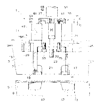
In Fig. 1, a turret punch press 1, for instance is
provided with a rotatable upper turret 3 and a rotatable lower
turret 5 as upper and lower die holders, respectively. In the
respective upper and lower turrets 3 and 5, a plurality of
turret holes 7 or 9 are formed at appropriate angular
intervals along the circumferences of the turrets 3 and 5,
respectively. A plurality of upper and lower dies 11 or 13
are fitted into the respective upper and lower turret holes 7
and 9, respectively.
Fig. 1 shows the state in which only one upper die 11 and
only one lower die 13 are mounted on the upper turret 3 and
the lower turret 5, respectively. In more detail with
reference to Fig. 1, a punch guide 15 movable up and down and
constituting a part of the upper die 11 is fitted to the
turret hole 7. A stripper plate 17 is attached to the lower
-3-
21 14887
portion of the punch guide 15 with the use of mounting
fixtures 19 and screws,
Further) a punch body 21 is fitted to the punch guide 15
so as to be movable up and down. Further, the punch guide 15
is formed with a key groove 23 so as to be engageable with a
key 25 of the punch body 21 and another key 27 of the upper
turret 3, respectively.
A punch driver 31 is provided on the upper portion of the
punch body 21 via a circular plate 29. In more detail, the
circular plate 29 and the punch driver 31 are fixed with a
plurality of bolts 33) and further the punch body 21 and the
punch driver 31 are fixed by a bolt 35.
A punch head 37 is provided on the upper portion of the
punch driver 31. Further) an elastically deformable damping
member 39 such as urethane is interposed between the upper
surface 61 of a flange portion 31F of the punch driver 31 and
the lower surface 62 of the punch head 37. The damping member
39 is interposed in an outer circumferential part 63 of a
space 64 between the upper surface 61 and the lower surface
62) and is not interposed in a inner circumferential part 65
of the space 64.
The distance C between the upper surface 61 and the lower
surface 62 in the outer circumferential part 63 is longer than
the distance D between the upper surface 61 and the lower
surface 62 in the inner circumferential part 65. In the inner
circumferential part 65) the upper surface 61 is aparted from
the lower surface 62 when the punch head 37 is not struck by
the striker 51, so as to provide the stroke in which the
damping member is deformed.
Further, as depicted in Fig. 2, a bolt 41 is inserted
into a groove 37G formed in the punch head 37 to fix the punch
head 37 to the punch driver 31.
A stripping spring 43 is interposed between the upper
-4-
21 14887
surface of the punch guide 15 and the flange portion 31F of
the punch driver 31 so as to always urge the punch driver 31
in the upward direction. In addition, a lift spring 45 is
interposed between the flange portion 15F of the punch guide
15 and the bottom of a hole 3H formed in the upper turret 3 so
as to always urge the punch guide 15 also in the upward
direction.
Further) on the upper side of the punch head 37) a
striker 51 movable up and down is attached on an upper frame
(not shown) for constituting a part of the turret punch press.
On theother hand, a die 47 constituting the lower die 13
is fitted to the turret hole 9 of the lower turret 5. The
lower die 47 is formed with a die hole 49 at a position
directly under the punch body 21.
On the basis of the above-mentioned construction) when
the striker 51 is lowered into collision against the punch
head 37, the shock is first absorbed by the deformation of the
lift spring 45. Thereafter) when the striker 51 is further
lowered, the punch driver 31 is also lowered. As a result)
the punch guide 15 is lowered by the downward motion of the
punch driver 31 via the stripping spring 43 against the
elastic force of the lift spring 45, and collides against the
work W placed on the lower die 47. Then the shock is absorbed
by the deformation of the damping member 39 interposed between
the upper surface 61 of the punch driver 31 and the lower
surface 62 of the punch head 37. Here, the reason why the
lift spring 45 is compressed is that the spring constant of
the lift spring 45 is determined to be smaller than that of
the stripping spring 43. Further, even when the stripper
plate 17 collides with the work W placed on the die 47, it is
possible to absorb the shock by the damping member 39, thus
preventing the punching noise generation.
In addition) an excessive deformation of the damping
member 39 can be prevented by the presence of the dimension
that the distance C in the outer circumferential part 63 is
longer than the distance D in the inner circumferential part
-5-
29 14887
65. In other words, since the punching force can be
transmitted from the punch head 37 to the punch driver 31
through the damping member 39 within a predetermined
deformation limit, it is possible to improve the life time of
the damping member 39.
When the stripper plate 17 collides with the work W,
since two metallic members collide with each other under a
very strong urging force of the stripping spring 43, the load
applied by the stripping spring 43, the damping member 39, and
the lift spring 45 increases abruptly as shown by a curve A in
Fig. 3, so that a shock is generated. In the punching die of
the present invention) since the damping member 39 is
interposed between the upper surface 61 of the flange portion
31F of the punch driver 31 and the lower surface 62 of the
punch head 37, it is possible to reduce the load applied by
the stripping spring 43 as shown by a curve B in Fig. 3) so
that a shock can be reduced effectively. Therefore) it is
possible to prevent the generation of punching noise, as
compared with the conventional punching die. Further, since
the damping member 39 is interposed between the upper surface
of the punch driver 31 and the lower surface of the punch head
37, the damping member 39 can be mounted easily.
The above-mentioned embodiment has been described only by
way of example. Without being limited thereto) however)
various modifications may be made. For instance, in the
embodiment shown in Fig. 1, the damping member 39 does not
exist between the upper surface 61 and the lower surface 62 in
the inner circumferential part 65. But even if the damping
member 39 is disposed extending into the space between the
upper surface 61 and the lower surface 62 in the inner
circumferential part 65) it is possible to obtain the same
damping effect as with the case of the above-mentioned
embodiment.
As described above) in the punching die according to the
present invention, since the elastically deformable damping
member is interposed between the upper surface of the punch
-6-
21 14887
driver and the lower surface of the punch head, it is possible
to prevent the generation of the punching noise effectively,
while making the life time of the damping member long and
facilitating the mounting process of the damping member on the
punching die.
15
25
35
_?_