Note: Descriptions are shown in the official language in which they were submitted.
21 1 4987
SHARPS DISPOSAL CONTAINER AND SYSTEM
Background of the Invention
This invention relates to disposal of contaminated
items, and in particular to a disposal system for use in
a hospital or similar environment where contaminated
items must be collected and disposed of without creating
a hazard for patients or hospital personnel.
In hospitals, clinics and similar medical
institutions, contamination continues to be of utmost
concern. With the prevention of the spread of
communicable diseases being a major priority, disposable,
single use patient-use care products have become quite
prevalent. Those items, once used, are contaminated and
can readily transmit disease. They include items such as
hypodermlc needles and other sharps, and are required to
be disposed of at their point of usage under current
guidelines of the United States Centers for Disease
Control. In U.S. Patents Nos. Re.33,413 and 4,779,728
sharps disposal systems are described. The present
invention is an improvement over those systems.
Summary of the invention
The invention provides a hollow, upstanding
container body, having an opening at the top of the
container body for permitted access to the interior of
21 14~87
the container body. A barrier is disposed proximate the
opening for restricting access to the interior of the
container body, at least a portion of the barrier means
comprises a first constriction extending over the opening
and a second constriction extending beneath the opening,
the second constriction being offset from the first
constriction forming an obstruction in the top of the
container body and a retention means for preventing items
from being dispensed through the opening from the
interior of the container body when the container body is
upright, at least a portion of the retention means
comprises the obstruction.
In accordance with the preferred form of the
invention, the disposal container includes a closure
disposed adjacent to the opening. The closure preferably
is pivotal, and the retention means comprises the
combination of two features of the invention, shaping of
a portion of the closure to extend across the opening and
positioning of the second constriction in an offset
fashion relative to the opening. The second constriction
comprises a cowl extending into the interior of the
container body, the cowl being located at one
longitudinal side of the opening and the closure being
- pivotally disposed at an opposite longitudinal side of
the opening. The closure pivots about a longitudinal
pivot axis, and the cowl is shaped to be radially
equidistant from the pivot axis at all locations.
-
''i ~.
,'
21 1 4987
2 a
The offsetting of the second constriction from thefirst provides a longitudinal obstruction extending
between the opening and the second constriction. The
closure is provided with a terminal end which is shaped
to engage that obstruction. Also, the closure, is
provided with a heel adjacent to the terminal end, with a
' heel being shaped to engage the first constriction when
the terminal end engages the longitudinal obstruction.
The closure also includes a portion shaped to engage
and close the first constriction. An activation flap
_ extends from,
2~i~9~7
and is coextensive with a terminal edge of that portion to permit
pivoting of the closure. The closure also includes means biasing
the closure such that it normally remains in an opened
orientation. Preferably, the biasing means is a counterweight,
the flap including the counterweight as an integral portion
thereof.
In accordance with the preferred forms of the invention, the
first constriction includes means for locking the closure to
prevent access to the interior of the container body when locked.
To this end, within the cowl of the first constriction is
included at least one catch. The catch includes a stop which
engages the closure when the closure is pivoted in one direction
past the stop into the interior of the cowl. At that
orientation, the stop prevents pivoting of the closure in an
opposite direction to reopen the container.
The disposal system according to the invention may include
the disposal container as an inner container within a hollow,
outer enclosure. The outer enclosure is sh~p~ to accommodate
and conform at least in part to the inner container. Preferably,
the outer enclosure includes a hood, with the hood being shaped
to conform to the first constriction and being located in
registration with the constriction when the container is located
within the outer enclosure.
Brief Description of the Drawings
The invention is described in greater detail in the
following description of examples embodying the best mode of the
invention, taken in conjunction with the drawings, in which:
2~ ~ 9~
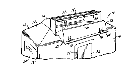
Figure 1 is a perspective view of a top portion of a
disposal system according to the invention, with one form of
disposal container located within a hollow enclosure, and with
the closure of the disposal container being fully opened,
Figure 2 is a view similar to Figure 1, but with the closure
of the disposal container being partially closed,
Figure 3 is a view similar to Figures 2 and 1, but with the
closure for the disposal container being fully closed,
Figure 4 is an enlarged partial cross sectional view through
only the disposal container illustrated in Figure 1, showing the
closure being in the opened orientation and illustrating
disposable sharps at various positions of disposal,
Figure 5 is a cross sectional view of the closure of Figure
4,
Figure 6 is a view similar to Figure 4, but with the closure
being partially closed just prior to dropping a small disposed
item within the container body,
Figure 7 is a view similar to Figure 6, but showing disposal
of a larger sharps,
Figure 8 is a view similar to Figure 6, but showing the
closure fully rotated so that the disposed item drops wit-hin the
container body,
~ igure 9 is a view similar to Figure 7, but showing the
closure fully rotated so that the large di~oscd sharps drops
within the container body,
Figure 10 is a view similar to Figures 8 and 9, but with the
closure fully rotated to a locked orientation,
211~7
Figure 11 is a cross sectional view similar to Figure 4, but
of a second embodiment of the invention, and showing a large
sharp in phantom as it is placed upon the closure for disposal,
Figure 12 i8 a view similar to Figure 11, but with the
closure partially closed, initially dropping the sharp to a
second orientation within the container body,
Figure 13 is a view similar to Figure 12, but with the
closure fully closed (but not locked), and showing the sharp
dropping within the container body, and
Figure 14 is a front elevational view of the closure of
Figures 11-13.
Description of Examples Embodying
the Best Mode of the Invention
A sharps disposal system according to the invention is
designated generally at 10 in the drawing figures. Primary
components of the system 10 are a hollow, outer enclosure 12 and
an inner, disposal container 14 shaped to be located within the
outer enclosure 12. The outer enclosure 12 is illustrated only
in Figures 1-3, it being evident that the inner disposal
containers 14 illustrated in the ensuing drawing figures,
although not illustrated in combination with an outer enclosure
12, are intended to fit within an outer enclosure in many, but
not nececc~rily all, instances of use.
The outer enclosure 12 includes an access door 16 secured
by one or more hinges 18 to a main body 20 of the enclosure 12.
Both the outer enclosure 12 and the inner container 14 are
preferably made of various plastic materials, and if the inner
container 14 is made of a translucent or transparent material,
211~g87
the door 16 can include a window 22 and the main body 20 can
include one or more windows 24 for viewing the contents of the
disposal container 14. One or more of the windows 22 and 24 can
include an indication 26 to show when the inner container 14 is
sufficiently fully of sharps that it should be removed and
emptied or replaced.
Other features of the outer enclosure 12 may be included as
desired. For example, preferably the door 16 includes some means
for it to be locked to avoid tampering with the contents of the
outer enclosure 12. Also, other adjunct features can be
incorporated into the outer enclosure 12, such as a glove
dispenser as disclosed in U.S. Patent No. 4,863,057. Any number
of other features might be incorporated in the outer enclosure
as desired.
The inner disposal container 14 is composed of a receptacle
28 and a top or cover 30 which is preferably snap-fitted onto the
receptacle 28 in a conventional fashion. Other means of
attachment can be employed as desired. The receptacle 28 and the
cover 30 are preferably formed of injection-molded plastic, and
if the windows 22 and 24 are employed in the outer enclosure 12,
it is preferred that at least the receptacle 28 be of translucent
or transparent material so that the contents thereof can be
viewed through the windows 22 and 24. Also, while the inner
disposal container 14 is shown being formed of two basic
components, the receptacle 28 and the cover 30, it should be
apparent that, depending on manufacturing capabilities and the
desire of the user, the receptacle 28 might be formed of more
9 ~ 7
than one piece, or the receptacle 28 and the cover 30 can be
formed in an integral fashion.
The cover 30 includes several features. It has an integral
cowl 32 extending over an opening 34 through the cover 30. The
opening is provided for permitting access to the interior of the
inner container 14, and the cowl 32 extends for the length and
width of the opening 34. Also, as best shown in Figures 1-3, the
cowl 32 is generally coextensive with a hood 36 formed in the
outer enclosure 12. The cowl 32 forms a first constriction
extending over the opening 34.
The cover 30 is provided with a second cowl 38 extending
beneath the cover 30 as shown. The cowl 38 forms a second
constriction extending beneath the opening 34, and the cowls 32
and 38 form at least part of a barrier for restricting access by
a user to the interior of the inner container 14.
A pivotal closure 40 is mounted in the cover 30 at one side
of the opening 34. The closure 40 extends for the length of the
opening 34, and includes pivot pins 42 at opposite ends thereof,
each of which extends into a pivot bracket 44 formed in the cover
30. Other means of pivoting can be employed, as well.
The closure 40 has an inner portion 46 shaped to extend
across the opening 34. The lower cowl 38 is offset from the
upper cowl 32, forming a longitudinal obstruction 48 extending
between the opening 34 and the cowl 38. The closure 40 also
includes a terminal end 50 extending from the inner portion 46
and shaped to engage the obstruction 48. A heel 52 is also
formed in the closure 40 at the juncture of the inner portion 46
and the terminal end 50.
21~ ~19~7
Opposite t~e pivot pins 42, the closure 40 includes an outer
portion 54 forming a platform for receipt of sharps and also
ex~ending sufficiently to close a mouth 56 of the cowl 32, as
best shown in Figures 8-10.
The outer portion 54 terminates at a flap 58 having a
curvature sufficient to mate with the curvature of the cowl 32.
The flap 58 also has a grip 60 to allow the user to readily
manipulate the closure 40 when using the disposal container 14.
The closure 40 pivots about a pivot axis extending through
the opposite pivot pins 42. The terminal end 50 extends to an
up-turned tip 62 proximate the cowl 38. The curvature of the
cowl 38 is such that the tip 62 is always in close proximity to
the cowl 38, and therefore preferably the cowl 38 is, at all
points, radially equidistant from the pivot axis extending
between the pins 42.
The terminal end 50 is downwardly offset from the inner
portion 46. The obstruction 48 is formed from an outward
offsetting of the cowl 38 from the opening 34. The obstruction
48 and terminal end 50 form a retention pocket or means 64 for
preventing sharps from being dispensed through the opening 34
from the interior of the container 14 when the container is
upright. The pocket 64 occurs because the closure 40 butts
against a shelf 66 formed in the cover 30. If the shelf 66 were
not included (as is the case in the second embodiment of Figures
11-14), the terminal end 50 would essential mate with the
ob~truction 48, eliminating any retention pocket per se, but
still providing the retention means, as explained further below.
Means is also provided for essentially permanently locking
the closure 40 to prevent access to the interior of the container
14. At least one catch 68 is provided in the cowl 32, in
alignment with an engaging member 70 formed in the flap 58. When
the closure 40 is fully rotated to the closed positioned shown
in Figure 10, the engaging member 70 engages behind the catch 6~,
preventing rotation of the closure 40 in the opposite direction.
In use, as shown in Figures 4-8, a used sharp 72, 74 or 76
is placed on the outer portion 54 of the closure 40 when opened,
typically one at a time. The user then pivots the closure 40
upwardly in relation to the grip 60, causing the sharp to first
fall into the container 14 and rest against the inner cowl 38.
Further rotating of the closure then causes the used sharp to
drop into the interior of the container 14.
During the disposal process, once a sharp 70-76 has fallen
sufficiently into the container 14 that it abuts the cowl 38, the
closure 40 cannot be reopened to inadvertently eject the sharp
from the interior of the container 14. This is due to the
downward offset of the terminal end 50 in combination with the
lateral offset of the cowl 38. Once a sharp is in the position
of the pocket 64, it is captured within the container 14, and
cannot be ejected back through the opening 34. Rather, the
closure 40 must continue to be pivoted until the sharp drops
within the interior of the container 14.
This phenomenon is first demonstrated with the relatively
large sharp 72. As shown in Figure 4, when the sharp 72 is to
be disposed, it is placed on the closure 40 and, although not
illustrated, due to the inclination of the closure 40, normally
211~g7
slides or rolls until it abuts the cowl 32 above the inner
portion 46. Then, as shown in Figure 7, the closure 40 is
pivoted, causing the sharp 72 to fall until it abuts the cowl 38.
At this position, the closure 40 cannot be pivoted in the
opposite direction, since the sharp 72 is lodged between the
obstruction 48 and either the terminal end 50 or the heel 52 (or
both). The user must further rotate the closure 40, as shown in
Figure 9, until the sharp 72 drops within the interior of the
container 14.
Similar results occur with smaller sharps 74 and 76. As
shown in Figure 4, once a sharp 74 or 76 is within the pocket 64,
it cannot be ejected since it is captured between the terminal
end 50 and the obstruction 48. Rather, in order to release the
sharp 74 or 76, the closure must be pivoted as shown in Figures
6 and 8 until the sharp drops within the interior of the
container 14.
Once the receptacle 28 has been filled or if it is desired
to remove a partially filled container 14 from the outer
enclosure 12, as shown in Figure 10, the closure 40 is pivoted
fully upright until the engaging member 70 engages behind the
catch 68. The closure 40 is then essentially locked in-place,
and the container 14 can be disposed of appropriately.
A second embodiment of the inner disposal container is shown
in Figures 11-14. While the container 14' is generally similar
to, and shares common basic features of, the container 14, some
differences exist, as well.
The container 14' is composed of two basic portions, a
receptacle 78 and a cover 80. The receptacle 78 can be identical
211~987
to the receptacle 28 of the first embodiment of the invention.
The receptacle 78 and the cover 80 may be joined in any fashion,
as explained in connection with the first embodiment of the
invention.
The cover 80 includes an upper cowl 82 extending above, and
coextensive with, an opening 84 to the interior of the receptacle
78. A second, lower cowl 86 extends beneath the cover 80 and
opening 84, in precisely the same manner as the first embodiment
of the invention. The cowl 86 may be an integral extension of
the cover 80, or, as illustrated, may include a peripheral flange
88 which is attached to the underside of the cover 80, such as
on a series of pins 90. The cowl 86 can be appropriately affixed
to the underside of the cover 88 in any conventional manner as
desired.
A closure 92 is pivotally mounted at one side of the opening
84. The closure 92 includes opposite pivot pins 94 engaged in
opposite sockets 96 formed in the cover 80. Therefore, the
closure 92 pivots about a pivot axis extending through the
opposite pivot pins 94.
The closure 92 includes an inner portion 98 shaped to close
the opening 84. The inner portion 98 includes a heel 100 which,
as shown in Figure 11, is shaped to engage the inner surface of
the cowl 82. A terminal end 102 extends from the inner portion
98, coextensive with an obstruction 104 formed by the offset of
the cowl 86 from the opening 84. The heel 100, terminal end 102
and obstruction 104 form a retention for preventing sharps from
being dispensed through the opening 84 from the interior of the
receptacle 78 in use, as explained in a bit greater detail below.
21149~7
The closure 92 also includes an outer portion 106, with an
activation flap 108 extending from an outer terminal edge of the
outer portion 106. The flap 108 extends to a grip 110 at a
distal edge thereof.
The closure 92 is freely pivotal about its pivot pins 94.
Preferably, the flap 108 and grip 110 are sized such that their
combined mass biases the closure 92 in the opened orientation
shown in Figure 11. The flap 108 and grip 110 counterweight the
oppositely extending inner portion 98 and terminal end 102. The
amount of material in the flap 108 and grip 110 can be chosen
judiciously so that the closure 92 allows automatic ejection of
a sharp 72 when placed on the inner portion 98, as explained in
greater detail.
For permanent locking of the closure 92 when the receptacle
78 is filled with waste or when it is desired to be discarded,
the cowl 82 includes at least one catch 112 extending downwardly
and in alignment with a series of apertures 114 formed in the
flap 108. The catch 112 forms a stop which engages the aperture
114 when the flap 108 is pushed to engage the catch 112 in an
aperture 114.
In use, a sharp 72 to be discarded within the container 14'
is placed on the inner portion 98. If sufficiently massive, the
weight of the sharp 72 causes the closure 92 to pivot as shown
in the sequence of Figures 11-13, dropping the sharp 72 within
the receptacle 78. If the sharp 72 does not have sufficient
weight to overbalance the counterbalancing of the weight of the
~ flap 108 and grip 110, the user can simply lift the flap 108 at
the grip 110, causing the sharp 72 to fall within the receptacle
211~9~7
78 in exactly the same fashion as explained in connection with
the first embod~ment of Figures 1-10. Also, due to the offset
forming the obstruction 104, in combination with the heel 100 and
terminal end 102, once a sharp 72 engages the lower cowl 86, it
is captured, and cannot be returned through the opening 84 if the
rotational direction of the closure 92 is reversed.
Once the receptacle 78 is filled or desired to be discarded,
the closure 92 is locked by pushing the flap 108 until the
catches 112 engage the apertures 114. The closure 92 is then
locked in place.
In this form of the invention, the user is prevented from
reaching into the interior of the receptacle 78 due to the
cooperation of the two cowls 82 and 86. In addition, as best
shown in Figure 12, the closure 92 cooperates with the cowls 82
and 86 to serve as a further barrier to the interior of the
receptacle 78. Only when the outer portion 106 is engaged
beneath the cowl 82 does the terminal end 102 extend past the
cowl 86. Therefore, the user is doubly protected from any means
of inadvertently extending fingers within the receptacle 78.
Various changes can be made to the invention without
departing from the spirit thereof or scope of the following
claims.