Note: Descriptions are shown in the official language in which they were submitted.
WC9 93/03236 . 2 1 1 ~ 0 4 4 PC~/CA92/11)032~5
BUXI~DING STRUCTURE
}I 13LD 01' I'IIE I ~
This invention relates to a building ~tructure and
more particularly to a decorative structural coLumn
having any desired shape or ~urface deslgn, ~nd a method
of formlng such a structure.
BACKGROUND OF THE_INVENTION
Columns formed from concrete or other suitable
material are commonly uqed in buildings and other type~
of structures. These columns are generally formed using
some sort of form or mold into which steel reinforcing
bar and concrete are inserted. After the concrete has
hardened, the form is ~tripped away to leave a standing
colu~nO
: The concr~te columns so formed gener~lly have an
; : irregula~ urface finish corresponding to the interior
.surface of the form. It is often a labour intensive a~d
:~: time consuminy operation t~ prepare and smooth the col~mn
:: 20 æurfac~s to an a~theti~lly more pleasing finish, In
a~diti~n, columns constructed using mold~ or foxms tend
:~ : to be l1mlted to:~a ~onstant circular or rectangular
cro~:s~ tion ~to~implify ~he required mold or fonm.
Col~mns ¢an be sculpted into a desired form af~r casting
:
2~ but this is an expen~ive and tLme consuming procedure
; : th~t requires highly skilled`craftsmen.
United~States Patent 2,505,426 to O'Flaherty
disclose a typical prior art concrete column molding
system that uses a *arpaper form. This system i~ lLmited
to ~ssentially cylindrical columns.
: United States P~atent 4 r 60~6 ,167 to Thorne discloses a
: method o~ en losing structural s~pporting columns such as
: ~ . .
SUBSTII~UTE SHEET
O ~1 4
r r
I-beams within a mould to produce a rounded column~ The
axrangement features the use of spaced ring members that
act as guides in the formation of a rounded exterior
surface. ~~~
.
United States Patent 4,887,789 to Harris et al.
discloses a mold fo~ forming sculpted or ornate column.
A mold must first be cut corresponding to the shape of
the desired column and the mold must be separated from
the cast column.
.,,
United States Patent 566,751 to Gilman discloses a
porous substrate adapted to accept a veneer of artificial
stone in order to form structural ornamental columns.
French Patent 1,369,144 discloses a structural form
omprising a hollow body of a desired cross-sectional
shape having a closed contour. The form comprises an
internal shell or core havin~ any desired cross-sectional
shape with outer covering and reinforcing layers of resin
and glass fi~res. ~he form can be filled with concrete.
The cent~ral shell or core has the same cross-sectional
20` s~ape:as the external form and the covering layers are
: : used to rei~force~and strengthen inner core, therefore,
each time a form with~a diffexent exter~al appearance is
required,~a new internal shell must~be~formed. ~:
Uni$ed States Patent 3,350,049 to Reiland discloses
5~ a concrete form that~uses:a central core formed into the
: d~Sired sh pe of the column to be constructed. The core ~:
is braced ~y an:~e:xternal tu~ul~ar support shell and by
~ : bracing material comprising foamed plastic material
: injected into the spaces betwe~n the core nd the support
; ~ 30 shell to prevent the core from distorting when concrete
: is poured into the corP. The form comprising the core,
- ~ the SUppoEt shell and:the bracing material is cut away
SUB5TI~IJTE SH~
r r r r
r 2 1 1 ~ 4 - ;
- 2a -
and discarded once the concrete has set to leave a
finished column~
SUMMARY OF THE INVENTION
There exists a need for a building s~ructure that
addresses -the problems of the prior art by providing a
column that can be easily formed into a desired
ornamental shape in a relatively inexpensive and
efficient process.
Accordingly, the pxesent invention provides a
building structure comprising~
a tubular member having an applied covering layer
that is formed into a desired shape;
an internal load bearing means within the interior
of sai~ tubular member. .
15~ In a furth~r aspect the present in~ention provides a
method of making a decorati~e building structure
comprising the steps of:
: : :
::
.
j
: ~ : :
~: :
'.:
5UBSTI~UT~: S~ T
W093/03236 PCT/CA92/0032~
21150~4
-- 3 --
applying a covering layer to the exterior of a
tubular member;
~ haping the covering layer to a desired form; and
installing a load bearing means within the inter1or
of ~aid tubular member.
In the method of the pre~ent invention, urethane
foam is the pref~rr~d ext~rior ~overing layer and the
tubular me~ber is formed from cardboard. This
arrangement provides a relatively lightweight, easily
manipulated structure that can be shaped into a desired
column shape on a lathe at the construction site or at a
remote location. Subsequently, the fonmed column can be
moved to the desired erec~ion ~ite and the reinforcing
bars and concrete installed.
~
~ he present inv~ntion is illustrated, merely by way
of exam~le in the accompanying drawings, in which:
~:: Fi~ure 1 is side elevation of a building structure
aocording~to the present invention; and
: 20 ~ ~igure:2 is a section:view taken along line 2~2 of
Figure l:showing the:cros~-~ectional a~rangement of the
buildi~g structure. ~:
C
::
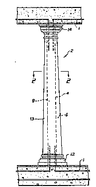
~: ~ Figure 1 show~ a building structure in the form of
an ornate column 2 constructed according to the present
: ~ ~nvention. The internal structure of column 2 is ~hown
: in Figure 2 which represents a typical cross section
through the column along the line 2 2~
SI~STI~UTE SHEET
W093/03236 PCT/CA92/00325
2 1 1 ~ 4 -
The ~tru~ture compxise~ a tubular member 4 having an
Applied covering layer 6 ~hat is formed into a desired
shape. In the preferred embodiment, tubular member 4 is
a cardboard tube of the type that is presently used as 2
disposable mold for concrete columns. The caxdboard tube
is generally referred to in the industry as a~ onotube".
The applied covering layer is any easily applied and
sculpted mat~rial. Preferably, applied covering layer 6
compri~es urethane foam that is sprayed onto the
cardboard tubular member. In forming a building
stru~ture according to the pre~ent invention, tubular
m~imber 4 can be set up in a lathe and rotated.. Vrethane
foam is applied to the rotating tubular member to
establish a ~ough shape that is oversize but approxLmates
1~ the final desired form of the building structure to be
created.
:~ Tube 4 and applied covering layer 6 pro~ide a
relatively light weight ructure that is easily
manipulated. WhiIe still on the lathe the covering layer
can be ~haped to the desired final shape and t~e coveri~g
~ æurface smoothed by ~anding to create an appropriate
: : fini~h using conventional tools.
,
~ The combined tube and~applied co~ering layer is then
: placed in position;at:th~desired lo~ation at the
construction ~ite. ~Internal load bearing means in the
form of~rei~f~rced concrete 8 is lnstalled within the
interior of tube 4~ to:areate a structural memb~r 2 with
~ anlornate exterior of any dè~ired shaped. Note in Figure
: l~that the load beari~g:mea~s preferably incorporates
: 30 rein~oxcing bars 1 that extend into the floor and
:~ceiling.
,
:~ ~While the building:structure of the present
invention can be formed~in part at a~ assembly plant and
~;~ the rest of the struGture: at the work site, a~ de~cribed
SUBSTITUTE SH~ET
WOg3/03236 2 11 ~ O ~ 4 PCT/CA92/00325
above~ it i8 al80 possible to as~emble the structure
entirely at a construction plant. For example, it is
possible to install the load bearing means when the
structure is being created and transport the completed
structure to the work site~
A~ an example, the column of Figure 1 has had its
applied covering layer 6 ~culpted into a colu~n having an
ornate base 12, a tap2ring shaft 13 and an ornate top 14.
The ~culpted applied ~overing layer has no real load
bParing aapa~ilitie~ and any load is supported by
internal concrete shaft 8 within cardboard tubular member
: 4 shown by da~hed lines.
It is intended that additional layers can be applied
: to the foam covering layer to:strengthen, waterproof or
:alter the app~arance of the~structure. :
A fabric or resin~;layer 16 can:be~applied to the
: outer:surface of the~sculpted covering layer 6 to
s~r~ng~hen:~the uretha~e~oam and prvvide desired
rigidity~
20~ A~re in layer~will~:t~end to:impregnate and saturate
the~;porous~foam~urf~ace~ Preferably~ the resin i5
I:pig~e~ted:;to uit:the~base colour of:::the de~ir~d
fini~hi~g layer~
: If~à~resin~layer~is~used, sand,~aggregate, copper or
25~ t;!le~aan~bel;~applied;~to~the resin layer to create a
;te~tured~ i6h.
A~paint~finish~18~ can also be applied to~th~
exte io~ of~the~struc~ure to give the appearance of a
textu~ed~finish~ ;A~"~faux";paint fini h can be used to
3~0~ create the~appearance~;~f marble, granite or other aux
finishes.~
SIJBSTITUTE SHEET
W093/03236 PCr/CA92/00325
211~0~ - 6 -
A final transparent clear coat 20 can be applied as
a protective coat and al~o a weatherproof finish.
The building structure of the present invention is
also intended for xetrofitting to existing structural
columns. A tubular member of appropriate di~n~ions-to
surround the existing column is selected and a co~ering
layer is applied and shaped as previously described. The
tubular form i8 then cut in half lo~gitudinally before
the final f ini~hing layers are applied. The tubular fonm
halves are fitted over khe existing structural columns
and glued together along their seams. Final finish1ng
can then be applied.
~ he present invention provides a relatively
inexpen~i~e and easily formed building structure that is
easily handled znd is aesth~ically pleasing to the eye.
While polyurethane foam has been specifically mentioned
as a preferred covering layer, it will be appreciated
that other yp~s o~ pla~tic fo~m material can also be
used.
20Although the present invention has been described in
: some detail by way of example for purposes of clarity and
under~tanding, it will: be~apparent that certain changes
a~d modifications may bi~:pra~tised within the scope of
: the~appended claims.
SU~STITUTE SHEET