Note: Descriptions are shown in the official language in which they were submitted.
~ ~13~)78
., 1
RECLAMATION OF THERMOPLASTIC WASTES
This invention relates to reclamation and reuse of
thermoplastic materials. More particularly, it relates to
densifying and reusing e~panded or foamed thermoplastic products,
waste materials and the like and reorming ~he same into useable
products.
-
Miany thermoplastic ~aterial~, ~uch a~ polyekhylene and
polystyrene, are foamed or expanded to contain gas cells or the
like for use as packaging or insulating ~ateirials. Typically,
polystyrene foam is expanded grom a density of approximately
sixty-two (62) pounds per cubic foot to le~s than one (1) pound
per cubic foot. The expanded foam is ~hen used for packaging
materials, insulating materials, etc. Howev~ir, cutting such
expanded thermoplastic materials to specific sizes and shapes for
specific uses creates great volumes of scrap or waste materials
which present a disposal problem. Since the material is expanded
and in the form of chips or fra~ments, it occupies high volumes
of space. Similarly, expanded or foamed materials used as
packing materials must generally be reused or destroyed.
Disposal of such wastes by burning produces toxic fumes. Because
it is expanded and bulky, conventional dispo~al systems become
rapidly overburdened and expensive.
Waste or scrap expanded thermoplastic material can be
recycled and densified for recycling by heating the material to
its softening point and permitting the trapped gas to escape.
Unfortunately, heating a foamed product consumes tremendous
amounts of eneirgy~ and thus has not proven to be a commercially
viable reclamation process.
In accordance with the present invention, expanded or foamed
thermoplastic material, sush as polystyrene, polyethylene, ~tc.,
is densified by confining a charge of particles thereof in ai
limited space and simultaneously reducing the volume while
agitating the particles. The agitation of particles against
particles (as well as molecular agitation) rapidly heats the
material to a temperature above its softening point and causes
the material to coalesce into a unitary~ liquid mass~ By
simultaneously agitating and compressing theimaterial, khe energy
produced by frictional forces is contained within the mass of
material itsel~, thus producing a li~uid mass with minimum
consumption of energy. Furthermore, the energy used is
essentially confined wi~hin the material ma~ ~o ~hat very littl~
energy in the form of heat i~ waited or lo~t to thie ~urrou~ding
atmosphereO
In another embodi~e~t of the invention, thie ~olteni ~a~s i~
immediately formed into a useable product by molding, Qxtrui~ion
or the like so that ~hie energy of formation contained withi~ the
molten mas~ is conserved. Thus ~iermoplastic waste material can
be rapidly converted into u~;eable product with minimum
consumption of energy. .The methods and apparatus of the
invention theref~re provide means for disposing of otherwise
hazardous waste materials and ~or converting iuch wa~te material~
into a useable product with minimum consumption o~ energy. Other
features and advantages of the invention will become more readily
understood from the ~ollowing detailed description taken in
connection with the appended claim~ and attached drawing in
which:
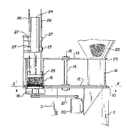
Fig. 1 is an elevational view of a pre~erred embodime~t o~
apparatus for practicing the preferred method of the invention:
and
Fig. 2 is a view of the apparatus of Fig. 1 taken through
line 2-2.
Apparatus ~or practicing the inveintion a~ illustrated in the
drawing comprises a support table 10 having a flat top and
suitable support structure such as legs 11. Parallel plates 12
and 13 are mounted on a spool 14 and supported on shaft 15
extending centrally through table 10 so that bottom plate 12 and
top plate 13 rotate in unison in parallel planes parallel with
the top surface of table 10. The lower surface o~ bottom plat2
12 is positioned adjacent the top of table 10 and may rotate
thereagainst.
Cylindrical chambers 16 (two of which are illustrated in the
drawing) extend from lower plate 12 to top plate 13 and the
portions of plates 12 and 13 defining the ends of the cylinders
removed so that open-ended cylinders 16 may rotate in a circle
~ L 1 ~i ~) 7 ~
about shaft 15. The bottom end of each cylinder i~ enclo~ed by
the top surface of table 10 and ~he top e~d of each cylinder 16
is open.
An aperture 17 i~ formed in table 10 (see Fiy. 2) which has
approximately the same dimensions of the lower open end of
cylinder 16. Aperture 17 is positioned in table 10 so that as
plates 12 and 13 are rotated, cylinder~ 16 are consecutively
moved into alignment coaxially wi~h the aperture 17. A rotatable
disc 18 is journaled in housing 19 and aligned with it~ upp~r
surface substantially parallel with the upper surfac~ o~ table
10. The disc lB is mounted on a shaft driven by drive motor 20
and belt 21, respectively. It will thus be observed that when
drive motor 20 is activated, disc 18 rotates in aperture 17 but
substantially fills the aperture 17, t~us enclosing the lower
open end of cylinder 16.
A hopper 22 mounted above the table has an open end 23 with
dimensions substantially conforming to and mating with open end
of cylinder 16 when cylinder 16 is located at a predetermining
position which is not coaxial with di~c 18. Comminuted material
contained in hopper 20 will thus ~low into and fill cylinder 16.
Since the lower end of cylinder 16 is open but adjacent the top
surface of table 10, the lower end of cylinder 16 is closed and
the cylinder is filled to capacity by comminuted material from
hopper 22. When cylinder 16 is filled, plates 12 and 13 are
rotated to move cylinder 16 into coaxial alignment with disc 18.
It will be observed that since table 10 is a flat surface, the
table 10 acts as a stationary bottom enclosure for moving
cylinder 16 and the material contained in cylinder 16 merely
slides over the top surface of table 10 until the cylinder is
aligned with disc 1~. Similarly, since top plate 13 is also has
a flat top surface, rotation of top plate 13 under hopper 22 acts
as a gate to stop flow of material from hopper 22 until another
cylinder 16 is aligned therewith. While only two (2) cylinders
16 are illustrated, any convenient number may be used and plates
~ ~ ~ l jv ï~
12, 13 rotated to con~ecutiv~ly po3ition one cyllnder in
alignment with di~c 18 while anoth~r cylinder 16 is align~d with
open end 23 for filing.
When a cylinder 16 filled with comminuted material is
rotated into alignment coaxial wi~h the disc 18, the top o~ the
cylinder is also positioned in coaxial alignment with a cylinder
24 which carries a top disc 25. Di3c 25 is thus also coaxially
aligned with disc 18. Cylinder 24 may be a hydraulic or air
actuated cylinder and, when ~ctivated, drives top disc 25 into
cylinder 16. In order to prevent rotation o~ the top disc 25,
elongated guides 26 are ~ournaled in bushings 27 and attached to
top disc 25. Thus as the top disc 25 moves downwardly into
cylinder 16, rotation of top disc 25 is prevented~
When a loaded cylinder 16 is aligned between top disc 25 and
disc 18, drive motor 20 is activated to rotate disc 18.
Simultaneously, cylinder 24 ic activated to urge top disc 25
toward bottom di~c 18, thus reducing the ~olume in cylinder 16.
Rotation of disc 18 causes extreme agitation and frictional
contact between particles of material contained within the
cylinder. As the volume of the cylinder is reduced, the friction
is increased and the volume of material is rapidly reduced.
Further agitation o~ the articles causes internal ~rictional
heating re~ulting in softening o~ the mat~rial and formation a
unitary molten mass.
Without being bound by any theory, it is believed that the
extreme ef~iciency of the process is attributable to friction
between the particles of material on a macro lev21 as well as
micro level. From experiments conducted, it is clear that heat
is generated within the material itself and not by frictiun
between the containing cylinder ~nd the material.
While comminuted particles of foamed materials are
illustrated, it only necessary that the particle be small enough
to fit into cylinder 16 and be agitated by rotation of disc 18.
Agitation of the particles causes the particles to rub against
l La~ ~
each o~her and thereby grind 2ach o~her into small~r particles.
To aid in agitation o~ tha particle , the ~ur~ac~ o~ di~c 18 may
be roughened or covered with a roughening materi~l ~uoh a~ sand
paper or ~h~ like.
Demonstration apparatu~ was constructed substantially as
illustrated in the drawing utilizing a steel cylinder 16 ~ourteen
(14) inches high and twelve ~12~ in inche~ in diamet~r. The
rotating disc 1~ was approximately twelve (12) inches in diameter
and driven by a 7.5 horsepower electric motor to rotate at
approximately 1800 rpm. The cylinder 16 was loaded with a charge
of comminuted polystyrene and cylinder 24 activated to ~orce disc
25 toward the opposite end of the cylinder, thereby compressing
the polystyrene foam. Using a pressure o~ about two (2) to thrQe
(3) pounds per square inch to force disc 25 into cylinder 16, the
foam was reduced to a unitary molten mas~ occupying approximately
0.011 cubic feet in about 15 to 30 seconds. The temperature of
the molten mass was determined to b~ approximately 250-C.
Repeated cycle~ of operations a~ de3cribad above produced
substantially identical results. Howev~r, the cylinder 16
remained substantially at room temperature and the temperature
of the rotating disc 18 never exceeded about 50-C. Accordingly,
it is believed that friction between particles o~ the loose foam
and the internal friction of the mass as a result of the kneading
action imparted to the mass by the rotating dis~. 18 results in
extremely rapid heating of the interior of the mass of material
to raise it to its softening point. Not only is the material
rapidly reduced to a so~tened, cohesive and unitary mass, the
~o~med material is coalesced into an esse~tially gas-free liquid.
Furthermore, the heat generated during the compression process
is retained within the mass of material and may be used to form
the material into useful products without reheating. For
example, the molten mass may be immediately placed in a suitable
mold or extrusion device and mslded or extruded into the desired
form to produce any of a variety of useful articles. The end
product, of course, ha~ ~ density of approximately ~ixty-two (62)
pounds per cubic foot (in ~h~ case o~ poly~tyrene).
Alternatively, ~he den~i~ied product may be shipped to a recycle
center for reuse.
The proces~ and ~pparatus o~ the invention work equally well
with foams o~ poly~tyrene and polyethylene. Other foamed
thermoplastic materials will prvduce ~imilar results. However,
the rate o~ compression, etc., may vary depending sn the dsnsity
o~ the foam, the softening point of the base material, etc.
Furthermore, particles o~ non-~oa~ed ther~opla~tic materials ~uch
as ABS plastic may also be r2fo~med into a heated mass in the
same mann2r and may even be mixed with foa~ed ~aterials such as
polystyrene to produce a blended finished product.
It should be noted that the invention advantageously
produces a substantially unitary mass of material which is at a
temperature above the softening point of the thermoplastic
material. Thus, the ~oftened mass may be im~ediately transform~d
into any desired shape without adding substantial energy in the
form of heat. Furthermore, ~uitable dyes, etcO, may be added to
the material at various stages in the process to color the end
product. For example, when using white expanded polystyrene, the
end product resembles a somewhat waxy-appearing marble. However,
by introducing small amounts dye or other material, the molten
mass may be formed into parts which have a distinctive marble-
like appearance. Other additives may be introduced to yield
other patterns, colors or visual e~fects as well as physical
characteristics. Similarly, fire retardant materials may be
added or other materials added which change the physical
properties of the end product. Accordingly, waste ther~oplastic
~oam may b~ ine~pensively con~erted using the methods and
apparatus of the invention into an almost endless variety of
useful and/or ornamental products.
It is has ~een determined that polyethylene foams densified
as described above produce a highly dense and extremely resilient
material which doe~ not fracture under extre~e ~tre~3. Th~
polystyrene product i extremely dense and re~ t.
While ~he chemical and/or physical nature o~ the r~forming
process of the invention is not fully under~tood, the ~orgoing
demonstrates that the process ha wide appliration in densifying
otherwi~e unusable and/or unde~irable ~hermnpla~tic material~ and
converting such otherwise unusiable ~aterial~ into u eful products
with minimum consumption of energy.
While the invention has bee~ de=cribed with particular
reference to a specific embodiments ~her~of, it i~ to be
understood that the forms of the in~ention shown and described
in detail are to be taken a~ preferred embodiments ~hereof.
Various changes and modifications may be resorted to without
departing from the spirit and scope of ~he invention as defined
by the appended claims.
,," ; " .~ ' ,,, '` , ' . .'. : . . j ' - ' ': 'i '