Language selection

Search

Patent 2115149 Summary

Third-party information liability

Some of the information on this Web page has been provided by external sources. The Government of Canada is not responsible for the accuracy, reliability or currency of the information supplied by external sources. Users wishing to rely upon this information should consult directly with the source of the information. Content provided by external sources is not subject to official languages, privacy and accessibility requirements.

Claims and Abstract availability

Any discrepancies in the text and image of the Claims and Abstract are due to differing posting times. Text of the Claims and Abstract are posted:

  • At the time the application is open to public inspection;
  • At the time of issue of the patent (grant).
(12) Patent: (11) CA 2115149
(54) English Title: A THROUGHFLOW VALVE AND A METAL MOULD TOOL FOR MANUFACTURING A VALVE SEAT OR A VALVE BODY
(54) French Title: ROBINET A PASSAGE DIRECT ET MOULE METALLIQUE SERVANT A FABRIQUER UN SIEGE OU UN CORPS DE ROBINET
Status: Term Expired - Post Grant Beyond Limit
Bibliographic Data
(51) International Patent Classification (IPC):
  • F16K 1/32 (2006.01)
  • F16K 1/34 (2006.01)
  • F16K 47/02 (2006.01)
(72) Inventors :
  • ANDERSSON, SVEN (Sweden)
(73) Owners :
  • FM MATTSSON AB
(71) Applicants :
  • FM MATTSSON AB (Sweden)
(74) Agent: KIRBY EADES GALE BAKER
(74) Associate agent:
(45) Issued: 2002-06-25
(86) PCT Filing Date: 1992-08-20
(87) Open to Public Inspection: 1993-03-04
Examination requested: 1999-06-28
Availability of licence: N/A
Dedicated to the Public: N/A
(25) Language of filing: English

Patent Cooperation Treaty (PCT): Yes
(86) PCT Filing Number: PCT/SE1992/000565
(87) International Publication Number: SE1992000565
(85) National Entry: 1994-02-07

(30) Application Priority Data:
Application No. Country/Territory Date
9102413-3 (Sweden) 1991-08-21

Abstracts

English Abstract


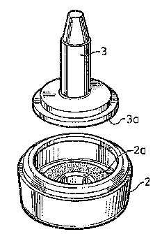
A throughflow valve (1) comprising a valve seat (2) and a
valve body (3) is intended to permit a given flow of fluid to pass
therethrough when the valve is closed. To this end, the mutually
abutting surfaces (2a; 3a) of the valve seat and/or the valve body
are irregular or roughened, these irregularities having a size of
20-100 µm. The invention also relates to a mould tool provided
with corresponding irregular or roughened surface created by a
so-called sparking operation.


Claims

Note: Claims are shown in the official language in which they were submitted.


6
Claims
1. A throughflow valve, provided with a valve seat and a
valve body, wherein the valve will permit a limited volume of
fluid to pass through the valve when the valve is closed with
the valve body in abutment with the valve seat, characterized
in that the surface of the valve seat and/or the surface of
the valve body is/are irregular or roughened so as to permit a
limited flow of fluid to pass between the irregularities in
the valve-seat surface and/or the valve-body surface.
2. A throughflow valve according to Claim 1, which is a
check valve or a safety valve for a damper means of a mixer
valve.
3. A valve according to Claim 1 or 2, characterized in that
at least the major part of the irregularities have a size
lying in the range of 20-100 µm.
4. A method for manufacturing the valve seat or valve body
of a throughflow valve according to Claim 1, 2 or 3,
comprising the step of providing a metal mould tool,
characterized in that the tool surface forming the seat
surface or the valve-body surface has an irregular surface
created by a sparking operation, wherein an electric voltage
is applied between the tool surface and an electrode so as to
generate an electric arc which pits the tool material to form
the irregularities therein, these irregularities then being
transferred to the valve seat or the valve body in a
subsequent injection moulding process.

7
5. A metal mould tool for manufacturing the valve seat or
valve body of a throughflow valve according to Claim 1, 2 or
3, characterized in that the tool surface forming the seat
surface or the valve-body surface has an irregular surface
created by a sparking operation, wherein an electric voltage
is applied between the tool surface and an electrode so as to
generate an electric arc which pits the tool material to form
the irregularities therein, these irregularities then being
transferred to the valve seat or the valve body in a
subsequent injection moulding process.

Description

Note: Descriptions are shown in the official language in which they were submitted.


~O X3104308 PGTlSE92/00555
1
A Throug~af low Valve and a Metal Mould Tool for
anuf ctu in a V lve Seat or a Valve Bod
Field of the Invention
The present invention relates to a throughflow valve having
a valve seat and valve body, particularly a check valve or
safety valve for mixer valve damping means, in which a
limited flow of fluid through the valve is permitted even
when the valve body lies against the valve seat.
According to another aspect, the invention also relates to a
metal mould tool for manufacturing the valve seat or valve
body of such a throughflow valve.
State of the Art
Througl~aflow valves, stack as check valves, in which a desired,
restxi~cted flow of fluid is permitted through the valve with
the aid of a V-shaped recess in the surface of the seat when
the valve is closed are kn~wn to the art. one serious draw-
back with'ualve seats of this kind, however, is that contami-
pants ~r fore~.gn bod~.es' present in the fluid that passes
through the valve are e~ail~r caught in the V-shaped recess,
thereby preventing the desired minimum flow of fluid or
'~3eakage" througk~ the ~ralve when the valve is closed. The
contaminants become wed~ed:in the recess and are liable to
jeopardize effective long-term functioning of the valve.
Alss known to the art are different 't~rpes of valves having.
sintered or'po~ous valve bodies or l~~rrier elements, which
permit a given flow of fZuid'through the valve when the valve
is closed. Exa~aiples of such valves are found described in
DE,AZ,,3.L40.438 (Wittenstein) and JP,A,61-96274 (Sumitomo
Electric). These valves,'however, are expensive to manu-
f~.cture and problems are encountered in aaGUrately deter-
mining the minimum amount of fluid that shall flow through

CA 02115149 2001-09-18
2
the valve, particularly since there is a risk that contami-
nants carried by the fluid will collect in the porous or
elastic valve material when the valve has been in use for
some time.
Other, related valves used for different purposes than the
aforesaid valves are described, for instance, in
US,A,3,185,438 (Smirra), EP,Al, 0 401 607 (Burkert) and
EP,A2,0 381 925 (Cummins Engine Company).
SE,B,8604612-5 (publication No. 455.124) (FM Mattsson)
describes a single-lever type mixer valve provided with a
damping arrangement which incorporates a throttle plate
functioning as a throughpass valve of the kind intended
here.
Obiect of the Invention
The object of the present invention is to provide at low
cost an improved throughflow valve which will avoid the
drawbacks of the earlier known, similar valves and which can
be used in different contexts.
Disclosure of the Invention
These and other objects are fulfilled by an inventive
throughflow valve of the aforedescribed kind and generally
characterized in that the surface of the valve seat and/or
the surface of the valve body is irregular or roughened so
as to permit a limited flow of fluid to pass between the
irregularities in the valve-seat surface and/or the valve
body surface.
This valve feature enables a minimum flow of fluid through
the valve to be ensured without blockaging of the valve, in
distinction to the earlier known valves.

CA 02115149 2001-09-18
3
Although fluid-carried contaminants may fasten in the
roughened or irregular surface, it has been found in
practice that these contaminants will be dislodged and
removed within a short period of time, the effect produced
by contact of the valve body with the valve seat also
contributing in this respect.
The contaminants thus have no tendency to become firmly
wedged, as in the case of valve seats provided with V-shaped
grooves.
In practice, at least the major part of the irregularities
should have a size in the order of 20-100 Vim.
The irregular or roughened surface can be produced in
practice by subjecting the metal mould tool used to manu-
facture the valve seat and/or the valve body to a "sparking
operation", wherein when manufacturing the mould tool a
voltage is applied between the tool and an electrode,
thereby generating an electric arc which "pits" the
material. The parameters applied during the sparking
operation are selected so that the tool surface will be
pitted with irregularities of a given desired size, which in
the subsequent injection moulding process used to
manufacture the valve seat or valve body will result in a
corresponding roughened or "pitted" surface of the injection
moulded seat.
Accordingly, another aspect of the invention relates to a
metal mould tool for the manufacture of a valve seat or
valve body of a throughflow valve of the kind intended here,
characterized in that the tool surface forming the seat
surface or the valve-body surface has an irregular surface
created by a sparking operation, wherein an electric voltage
is applied between the tool surface and an electrode so as
to generate an electric arc which pits the tool material to

CA 02115149 2001-09-18
3a
form the irregularities therein, these irregularities then
being transferred to the valve seat or the valve body in a
subsequent injection moulding process.
Brief Description of the Drawings
The invention will now be described in more detail with

W~ 93/Q430~ ~ .~ ~ ~ ~ ~ ~ P~.'f/~~92/OOS6S! .'
4
reference to an exemplifying embodiment thereof and also with
reference to the accompanying drawings, in which
Figure ~. is a perspective view of the two valve parts, namely
the valve seat and the valve body of an inventive t~roughflow
valve; and
Figure 2 is a cross-sectional view of a closed throughflow
valve which permits a limited minimum flow of fluid there
through.
Best Mode of Carrying Out the Zn~rer~tion
The throughflow valve 1. illustrated in the drawing comprises
a valve seat 2 and a valve body 3. The valve seat 2 has a
seat surface 2a which abuts a corresponding surface 3a on the
valve body 3 when'the valve is closed; as shown in Figure 2.
In order to permit a given aninimum flow of fluid to pass
through the valve when the valve is closed, the seat surface
2a is "pitted", i.e: is roughened with a large number of
irregularities havine~ a size which may lie in the range ~f
20-x.00 ~m and which in he case of an embodiment applied in
practice has a size of 40-60 ~Cm.'
The xoug)nened or pitted surface is produced when manufactur-
ing the valve seat by virtue of the fact that the surface of
a mould tool used. to manufacture'the seat surface is subj~ct-
ed to a so-called spar7cing operation so as to form a rough-
ened or irregular surface corresponding to the surface of the
valve seat. In this regard, an electric voltage is applied
between the surface of'the m~uld tool and an electrode, so as
to generate an electric arc and therewith pit the tool mate-
~rial so as to form an irregular or pitted surface thereon.

I' WO 93/0430 ~ ~ ~ '~ ~ ~ ~ PCfi/5E92/0~565
Alternatively, or additionally, the seat abutment surface 3a
of the valve body 3 may be provided with a corresponding
roughening or irregularities. Normally, however, it is suff i-
cient for only one of the surfaces to be roughened, the valve
5 seat part being chosen for this purpose in the majority of
cases.
The seat part and the valve body respectively may be made of
any desired material, such as a plast~.c material or metal.
The roughened surface can be produced in many ways other than
the preferred method described above. For example, a computer
controlled copy milling machine can be used for the aforesaid
purpose instead of the sparking operation.
The size of the irregularities may vary in accordance with
the use for which the throughflow valve is intended.

Representative Drawing
A single figure which represents the drawing illustrating the invention.
Administrative Status

2024-08-01:As part of the Next Generation Patents (NGP) transition, the Canadian Patents Database (CPD) now contains a more detailed Event History, which replicates the Event Log of our new back-office solution.

Please note that "Inactive:" events refers to events no longer in use in our new back-office solution.

For a clearer understanding of the status of the application/patent presented on this page, the site Disclaimer , as well as the definitions for Patent , Event History , Maintenance Fee  and Payment History  should be consulted.

Event History

Description Date
Inactive: Expired (new Act pat) 2012-08-20
Inactive: IPC from MCD 2006-03-11
Grant by Issuance 2002-06-25
Inactive: Cover page published 2002-06-24
Inactive: Final fee received 2002-04-09
Pre-grant 2002-04-09
Notice of Allowance is Issued 2001-11-01
4 2001-11-01
Letter Sent 2001-11-01
Inactive: Approved for allowance (AFA) 2001-10-23
Amendment Received - Voluntary Amendment 2001-09-18
Inactive: S.30(2) Rules - Examiner requisition 2001-03-22
Amendment Received - Voluntary Amendment 2000-01-25
Inactive: Application prosecuted on TS as of Log entry date 1999-07-13
Letter Sent 1999-07-13
Inactive: Status info is complete as of Log entry date 1999-07-13
All Requirements for Examination Determined Compliant 1999-06-28
Request for Examination Requirements Determined Compliant 1999-06-28
Application Published (Open to Public Inspection) 1993-03-04

Abandonment History

There is no abandonment history.

Maintenance Fee

The last payment was received on 2001-07-20

Note : If the full payment has not been received on or before the date indicated, a further fee may be required which may be one of the following

  • the reinstatement fee;
  • the late payment fee; or
  • additional fee to reverse deemed expiry.

Patent fees are adjusted on the 1st of January every year. The amounts above are the current amounts if received by December 31 of the current year.
Please refer to the CIPO Patent Fees web page to see all current fee amounts.

Owners on Record

Note: Records showing the ownership history in alphabetical order.

Current Owners on Record
FM MATTSSON AB
Past Owners on Record
SVEN ANDERSSON
Past Owners that do not appear in the "Owners on Record" listing will appear in other documentation within the application.
Documents

To view selected files, please enter reCAPTCHA code :


To view images, click a link in the Document Description column (Temporarily unavailable). To download the documents, select one or more checkboxes in the first column and then click the "Download Selected in PDF format (Zip Archive)" or the "Download Selected as Single PDF" button.

List of published and non-published patent-specific documents on the CPD .

If you have any difficulty accessing content, you can call the Client Service Centre at 1-866-997-1936 or send them an e-mail at CIPO Client Service Centre.

({010=All Documents, 020=As Filed, 030=As Open to Public Inspection, 040=At Issuance, 050=Examination, 060=Incoming Correspondence, 070=Miscellaneous, 080=Outgoing Correspondence, 090=Payment})


Document
Description 
Date
(yyyy-mm-dd) 
Number of pages   Size of Image (KB) 
Claims 1995-09-15 1 57
Abstract 1995-09-15 1 62
Description 1995-09-15 5 311
Drawings 1995-09-15 1 35
Claims 2000-01-24 2 52
Description 2001-09-17 6 279
Representative drawing 2002-05-29 1 16
Representative drawing 1998-07-19 1 15
Reminder - Request for Examination 1999-04-20 1 117
Acknowledgement of Request for Examination 1999-07-12 1 179
Commissioner's Notice - Application Found Allowable 2001-10-31 1 166
PCT 1994-02-06 8 357
Correspondence 2002-04-08 1 35
Fees 1996-08-11 1 73
Fees 1995-08-13 1 59
Fees 1994-08-10 1 48