Language selection

Search

Patent 2115181 Summary

Third-party information liability

Some of the information on this Web page has been provided by external sources. The Government of Canada is not responsible for the accuracy, reliability or currency of the information supplied by external sources. Users wishing to rely upon this information should consult directly with the source of the information. Content provided by external sources is not subject to official languages, privacy and accessibility requirements.

Claims and Abstract availability

Any discrepancies in the text and image of the Claims and Abstract are due to differing posting times. Text of the Claims and Abstract are posted:

  • At the time the application is open to public inspection;
  • At the time of issue of the patent (grant).
(12) Patent: (11) CA 2115181
(54) English Title: SEWAGE WATER PUMPING STATION, AND A TANK THEREFOR
(54) French Title: STATION DE POMPAGE D'EAUX USEES ET RESERVOIR
Status: Expired and beyond the Period of Reversal
Bibliographic Data
(51) International Patent Classification (IPC):
  • E03F 05/10 (2006.01)
  • E03F 05/22 (2006.01)
  • F04D 29/60 (2006.01)
(72) Inventors :
  • PETTERSSON, NILS-ERIK (Sweden)
(73) Owners :
  • ITT FLYGT AB
(71) Applicants :
  • ITT FLYGT AB (Sweden)
(74) Agent: SMART & BIGGAR LP
(74) Associate agent:
(45) Issued: 1997-12-09
(22) Filed Date: 1994-02-08
(41) Open to Public Inspection: 1994-08-12
Examination requested: 1994-02-08
Availability of licence: N/A
Dedicated to the Public: N/A
(25) Language of filing: English

Patent Cooperation Treaty (PCT): No

(30) Application Priority Data:
Application No. Country/Territory Date
9300444-8 (Sweden) 1993-02-11

Abstracts

English Abstract


The tank has vertical walls joined to a
horizontal bottom with a diagonal wall
bridging between an intermediate portion
of one of the vertical walls and the
bottom. The diagonal wall has an access
opening formed therein, and it cooperates
with the one vertical wall and the bottom
to form a sheltering recess, in the tank,
for pumping station components. The
pumping station has the relevant components
emplaced in the tank, and sewage water
admitting and discharging facility, with
a submersible pump and water-handling
piping. Station components, and portions
thereof, are sheltered in the recess of
the tank, to accommodate an optimum water
flow in the tank, and to minimize an
entanglement of solid objects with the
components.


French Abstract

Réservoir comportant des parois verticales assemblées à un fond horizontal, avec paroi diagonale reliant au fond une partie intermédiaire d'une des parois verticales. La paroi diagonale comporte une ouverture d'accès formée à l'intérieur et coopère avec une paroi verticale et avec le fond pour former un logement, dans le réservoir, pour les éléments constitutifs de la station de pompage. Les éléments constitutifs de la station de pompage sont placés dans le réservoir, avec les dispositifs d'aspiration et de refoulement des eaux usées, une pompe submersible et la tuyauterie nécessaire. Les éléments constitutifs de la station de pompage et des parties de ces éléments sont placés dans le logement du réservoir afin d'assurer un débit optimal d'eau dans le réservoir et de réduire au minimum l'enchevêtrement d'objets solides avec les éléments constitutifs.

Claims

Note: Claims are shown in the official language in which they were submitted.

I CLAIM:
l. A tank, for a sewage water pumping station, comprising:
substantially vertical walls;
a substantially horizontal bottom; and
at least one diagonal wall, having upper and lower ends;
wherein
said upper end is joined to one of said vertical walls, and said
lower end is joined to said bottom;
said diagonal wall has an opening formed therein;
said one vertical wall, said bottom, and said diagonal wall cooperatively
define means for forming a recess within said tank; and
said opening comprises an access to said recess.
2. A tank, according to claim 1, wherein:
said one vertical wall has a given depth; and
said upper end is joined to said one vertical wall at approximately
half said given depth.
3. A tank, according to claim 1, wherein:
said one diagonal wall is formed of sheet metal.
4. A sewage water pumping station, comprising:
a tank having (a) substantially vertical walls, (b) a substantially
horizontal bottom, and (c) at least one diagonal wall, having upper and
lower ends; wherein
said upper end is joined to one of said vertical walls, and said
lower end is joined to said bottom;
said diagonal wall has an opening formed therein;
said one vertical wall, said bottom, and said diagonal wall cooperatively
define means for forming a recess within said tank;
at least one submersible pump confined within said tank;
connection support means (a) aligned with said pump, and (b) confined
within said recess;

means formed in one of said vertical and diagonal walls for admitting
sewage water into said tank; and
means in ccmmunication with said pump for discharging sewage water
from said tank.
5. A sewage water pumping station, according to claim 4, wherein:
said discharging means comprises an outlet pipe: and
an end of said pipe is joined to said connection support means, and is
confined within said recess.
6. A sewage water pumping station, according to claim 4, further
including:
a longitudinal guide, within said tank, and substantially vertically
disposed therein; wherein
said connection support means has means for receiving an end of said
guide: and
said end of said guide is removable from said receiving means for
extraction thereof from said tank.

Description

Note: Descriptions are shown in the official language in which they were submitted.


~1 1 51 81 Pettersson-l
A SEW~GE WATER PUMPING STATION, AND
A TANK 'l'~K ~ ~ UK ; :
Ba~hyLu~d of the Invention
This invention relates, generally, to sewage water p Q ing stations, and tan~s
therefor, and in particular to impruv~ Ls thereof for inhibiting clogging of
the pump by sludge banks and/or solid bodies.
Pumping stations of the type with which this invention is conu~L~.ed are provided
with one or more inlets for the sewage water and normally one outlet pipe, the
latter being in communication with the pump outlet or discharge. An example of
such is disclosed in Swedish Patent No. 366,013, and its corL~u,lding U.S.
Patent No. 3,957,633, issued on 18 May 1976, to Giuliano Gatti, et al, for
a Sewage -L~ai t Method and Apparatus.
In typi~al prior art, a submersible pump unit, comprising the sewage water pump,is normally lowered into the sewage water, confined within the pumping station
tan~, along guides. It is so arranged that the pu~p unit, in its fully lowered
position, aligns its outlet with the outlet pipe within the station tank. The ~-
pu~p unit must seal against the outlet pipe of the station tank without any bolting
or fasteners of any ~ind. For this purpose, a so-called connection support is
arranged at the bottom of the station tank, and is provided with a pip2 part,
attached to the outlet pipe at one end, and having a flange at the opposite end.A CoLL~ ;n~ flange on the pump contactingly aligns with the connection support
flange. T~ ends of the guides are coupled to th~ connection support.
Sewage water c~ntainq a lot o~ solid bodies, such as sludge, which are;readily
a~ rated on the tank bottom as sludge banks, rags and other, elongated objects. ~ -
Such may wind around the pump unit and its connecting parts. Too, sludge ban~s
and rags are a hindrance to the circulation within the tank, and may also clog the
pump inlet.
,,;,

8 1
It iq a known practice, to solve the problem with the sludge banks in the
tan~, by means of intermittingly-operating, mixing devices of the type shown
in the Swedish Patent No. 8900 597-9, and its co~s~ in~ U.S. Patent
No. 4,948,342. Another method, drawn to the same purpose, is to install
~ ne.c or devices which ~eep the sewage water m~ving within the tank.
Yet another method which is used to prevent sludge from collecting at the
bottom of the tank is to design the bottom with st~ep slopes, and then arrange
the pump inlet at the lowest point in the tank. However, even here, there
remains the problem that elongated objects stick to the guides, the connection
supports for the pump, and related, pump unit connecting parts.
Summary of the Invention
It is an object o~ this invention to d;sclose a sewage water pumping station,
and a tank there~or, which ~n~ '7,~s tlle sludge collection at the bottom o~
the tank, and inhlbits the intrusion of elongated objects into the connection
su~port for the punp, pump unit connecting parts, and the guides.
Particularly, it is an object of this invention to set forth a tank, for a
sewage water pumping station, comprising su~stantially vertical walls; a sub-
st~nti~lly horizontal bottom; and at least one ~iagon~l wall, having upper and
lower ends; wherein said upper end is joined to one o~ said vertical walls, and
said lower end is joined to said bottom; said d;a~on~l wall has an opening
formed ~herein; said one vertical wall, said bottom, and said diagonal wall
cooperatively define means for forming a recess within said tank; and said
opening co~prises an access to said recess.
It is also an object of this invention to ~ic~lose a sewage water pumping
gtation, co~prising a tank having (a) substantially vertical walls, (b) a
s~L~an~ially horizontal bottom, and (c) at least one ~iag~n~l wall, having
upper and lower ends; wherein said upper end is joined to one o~ said vertical -
walls, and said lower end is joined to said bottom; said dia~on~l wall hac an
opening ~ormed therein; said one vertical wall, said bottGm and said ~;~gon~1
wall cooperatively define means ~or forming a rece~s within said tank; a~ least
-- 2 --
. .
,

~ 2~ 15181
one ~ lble pump confin~d within said tank; connection support means (a)
aligned with said pump, and ~b) confined within said recess; mean~ formed in
one of said vertical and ~ n~ walls for admitting sewage water into said
tank; and means in communication with said pump for discharging ~ewage water
from said tank.
Further objects of this invention. as w011 as the novel features thereof, will
be apparent by reference to the following description, taken in con~unction
with the ~ ying figure.
Brief Description of the Figure
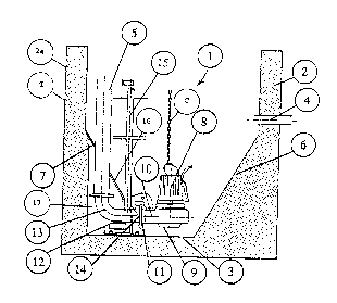
The figure is a vertical, cross-sectional view, taken through the tank, according
to an ~-'t t of the invention, showing the novel sewage water pumping
station, also according to an '_~t -~ of the invention.
Description o~ the Preferred r '~It t9
- .
' .
As shown in the figure, the novel sewage water pumping station 1, comprises -a tank "T" having vertical walls 2 and 2a, and a horizontal bottom 3. An opening
4, formed through waLl 2, comprises an inlet for sewage water into the tank ~'r .
An outlet pipe 5 comprises the means for discharging sewage water from the
tank "T". Diagonal walls 6 and 7 are joined to the vertical walls 2 and 2a,
respectively, at upper ends thereof, and to the bottom 3, at lower ends thereof.Wall 6 is formed of ~ e, whereas wall 7 is formed of sheet metal. A sub~
mersible pump 8 is confined within the tank "T"; it has an inlet 9, and an
outlet 10.: The outlet 10 has a flange 11 for mating with a connection support
12 whi~h i9 fastened to the bottom 3 of the tank. The connection support 12
has a pipe 13 ~hi~h aligns with the outlet pipe 5, and has a flange 14 which
inter~aces and aligns with the flange 11. Longitudinal guides 15 (only one is
shown) have ;~~~ 9~ ends thereof removably coupled to the connection support 12
by means of annuluses formed on the connection support 12.
The pumping station 1 is fed sewage water throuyh the opening ~, and the wa~er
leaves the tank "T" through the pipe 5. The pumping is provided by the sub-
mersible pump 8 via the inlet 9 and outlet 10 thereo~.
-- 3 --

21~181
,~
In order to l~n~ the ag~l~ ~ration of sludge banks in the bottom of thetan)c "T", the ~;agnn~l walls 6 and 7 are provided~ As can be seen, the inlet
9 for the pump 8 is located whereat the inner ends of the walls 6 and 7 approachcullvtly~ ~, and where most of the solid bodies will collect.
m e pump 8 is lowered down to the bottom of the tank "T" along the guides 15 tand
in this ~ two guides are employed, albeit only one i9 shown). The guides
15 ~o position the outlet 10 of the pump 8 that its flange 11 interfaces and
aligns with the flange 14 of the pipe 13. The alignment and ~ n~i~n;ng are
such that there is no need for the two flanges 11 and 1~ to be fastened together,
and the punp outlet 10, nonetheless, is sP~l;n~ly in ~ tion with the pipe
13 and, concomitantly, with the pipe 5. Due to this a~L. ~ ~, the pump 8
can be easily hoisted, up along the guides 15, by the chain ~C~I for ~ intDn~n~eor rPr1~l t.
As previously mentioned, it often happens that elongated objects, rags, and the
like, get intrusively entangled with co M ecting and/or proj~cting parts of ~he
the tau~c-confined . ts. According to a feature of the invention, the
connection support L2, a part of the outlet pipe 5 and the lowermost end o~ the
guides 15 are shielded, substantially, from the aforesaid objects, rags, and such. ~ :
Wall 7 has an opening 16 formed therein to ~ te the pipe 5, connection
support 12 and guides 15. Wall 7, in cooperation with wall 2a, and bottom 3
defin~s. ~ recess 17 in which to house the inn~ ~~ end of pipe 5, the pipe
13, -~uL~L~n~ially all of the connection support 12 and the innP r~ or lowermostends of the guides 15. In this way, the number of projecting parts within the
tanX ~T" exposed to the trollhlr solids in the sewage water are considerably
d;r;ni~hpd. mis provides for a better flow of the sewage water within the
tank "T", and inhibits th0 a~ dtion of elongated fibers, rags, and other
colids. . -
As previously noted,-the wall 7 is formed of sheet metal. Alternatively,
however, this d;~n~l wall could be formed of ~ r~e providing that, in the
forming thereof, a suitable r ffl ss, such as r ffl ~s 17, is formed therein during
the casting. m e use of sheet metal, of course, makes it readily feasible..to
modify e~cisting pumping stations for the benefits of this in~ention. In eithercase, i.e., where the recess 17 is forned by means of an opening in a sheet metal
wrdll or ~v~ e~e wall, a suitable cover (not shown) can be positioned over those

: '
1 8 1
portions of the opening 16 which are not penetrated by the pipe 5, guides 15,
and c~nn~ction support 12. It can be arranged for such cover to be t~ee~,
after the mounting o~ the connection support 12 and the pump 8, and for the cover
to accompany the pump 8 ~hen the latter is hoisted out for maintenance and/or
r~pl~
The p Q 8, as can be seen, is positioned so that its inlet 9 is close to the
bottom 3 of the tank "T", and in proximate adjacency to the lower end of the
n;a~on~7 wall 7. Inlet 9, in fact, is sited whereat the walls 6 and 7 approach
their ~ vely~lce. Accordingly, the inlet 9 is located where heavy objects tendto collect and, therefore, can readily be pumped out; thus the problem of
a~ ing sludge banks is substantially eliminated. The slope of the walls
6 and 7, to yield the desired effect, is between approximately forty to sixty
degrees of arc with reference to the horizontal plane.
Further, to 'nl '7P the lik~1~h~o~ that sludge banks and solids will impede
water flow in the tank "T" and/or collect about the guides 15, it is arranged that,
after the connection support 12 and pump 8 are positioned in the tank "T", the
guides 15 can be removed. They are wholly removed from the tank "T", until
they have to be used again for removal of the pump 8 for maintenance or replace-ment, by slidably extracting them from the connection support 12.
While I have described my invention, in connection with specific ~ ~_a~ Ls
thereof, it is to be clearly w.der~ood that this is done only by way of example,and not as a limitation to the scope of the invenSion, as set forth in the
objects thereof, and in the ~ d claims.
.
- 5 -
:: ., : ,,,; , . ,,; :.,". ,,: ~ :

Representative Drawing
A single figure which represents the drawing illustrating the invention.
Administrative Status

2024-08-01:As part of the Next Generation Patents (NGP) transition, the Canadian Patents Database (CPD) now contains a more detailed Event History, which replicates the Event Log of our new back-office solution.

Please note that "Inactive:" events refers to events no longer in use in our new back-office solution.

For a clearer understanding of the status of the application/patent presented on this page, the site Disclaimer , as well as the definitions for Patent , Event History , Maintenance Fee  and Payment History  should be consulted.

Event History

Description Date
Time Limit for Reversal Expired 2012-02-08
Letter Sent 2011-02-08
Inactive: IPC from MCD 2006-03-11
Grant by Issuance 1997-12-09
Inactive: Application prosecuted on TS as of Log entry date 1997-10-01
Inactive: Status info is complete as of Log entry date 1997-10-01
Pre-grant 1997-08-01
Notice of Allowance is Issued 1997-03-04
Application Published (Open to Public Inspection) 1994-08-12
Request for Examination Requirements Determined Compliant 1994-02-08
All Requirements for Examination Determined Compliant 1994-02-08

Abandonment History

There is no abandonment history.

Fee History

Fee Type Anniversary Year Due Date Paid Date
Final fee - standard 1997-08-01
MF (patent, 4th anniv.) - standard 1998-02-09 1998-01-16
MF (patent, 5th anniv.) - standard 1999-02-08 1999-01-18
MF (patent, 6th anniv.) - standard 2000-02-08 2000-01-19
MF (patent, 7th anniv.) - standard 2001-02-08 2001-01-15
MF (patent, 8th anniv.) - standard 2002-02-08 2002-01-21
MF (patent, 9th anniv.) - standard 2003-02-10 2002-10-15
MF (patent, 10th anniv.) - standard 2004-02-09 2003-11-25
MF (patent, 11th anniv.) - standard 2005-02-08 2005-01-20
MF (patent, 12th anniv.) - standard 2006-02-08 2006-01-12
MF (patent, 13th anniv.) - standard 2007-02-08 2007-01-11
MF (patent, 14th anniv.) - standard 2008-02-08 2008-01-11
MF (patent, 15th anniv.) - standard 2009-02-09 2009-01-12
MF (patent, 16th anniv.) - standard 2010-02-08 2010-01-18
Owners on Record

Note: Records showing the ownership history in alphabetical order.

Current Owners on Record
ITT FLYGT AB
Past Owners on Record
NILS-ERIK PETTERSSON
Past Owners that do not appear in the "Owners on Record" listing will appear in other documentation within the application.
Documents

To view selected files, please enter reCAPTCHA code :


To view images, click a link in the Document Description column. To download the documents, select one or more checkboxes in the first column and then click the "Download Selected in PDF format (Zip Archive)" or the "Download Selected as Single PDF" button.

List of published and non-published patent-specific documents on the CPD .

If you have any difficulty accessing content, you can call the Client Service Centre at 1-866-997-1936 or send them an e-mail at CIPO Client Service Centre.


Document
Description 
Date
(yyyy-mm-dd) 
Number of pages   Size of Image (KB) 
Abstract 1995-06-07 1 38
Description 1995-06-07 5 263
Claims 1995-06-07 2 87
Drawings 1995-06-07 1 48
Representative drawing 1997-11-27 1 22
Maintenance Fee Notice 2011-03-21 1 170
Fees 1997-01-15 1 51
Fees 1996-01-14 1 45
PCT Correspondence 1997-07-31 1 31