Note: Descriptions are shown in the official language in which they were submitted.
26541-94
AN APPARATUS IN THE FORM OF A COMPOUND FOIL FOR THE
COLORIMETRIC INDICATION OF GAS
The present invention`relates to an apparatus for the
colorimetric indication of gas and/or vapour constituents in a
gas mixture, which passes into one or a plurality of reaction
zones that are made in a carrier in the form of channels, on the
bottom surfaces of which a colour indicator is applied, with
which the constituents that are to be indicated enter into a
colour reaction.
An apparatus of this type is described in DE-PS 39 02 402.
In this known apparatus, channel-like depressions are made in a
carrier and each of these contains a colour indicator and
additional reactants for the colorimetric indication reaction.
The reactants in each of the channels can be identical or
different, depending on whether multiple indication of the same
gas constituents is to be conducted or whether various gas
constituents in air are to be indicated. Each of the channels
has at least one opening to admit the toxic substance that is to
be indicated, and this is either drawn through the channels or
else diffuses into the channel. Each individual channel thus
acts like a conventional single test tube for the colorimetric
~ ~ 7 ~ ~
indication of gaseous constituents in air. By arranging a
plurality of channels in parallel on the carrier, one obtains a
miniaturized version of a multiple measurement apparatus for the
colorimetric indication of gaseous toxic substances. The chip-
like carrier is analyzed by an opto-electronic scanning
apparatus. To this end, a sender and a detector unit are guided
automatically to the same level and in an identical extent to
each of the individual channels and the light that is reflected
from the coloured channel zone is analyzed. The length of the
colouration zone provides information with respect to the
concentration or quantity of the gas constituents that are to be
examined that is present in the indication sample, depending on
whether the channels are used as test tubes in a flow-through
procedure or as dosimeters, by means of diffusion of the toxic
substance.
In the known apparatus, the reaction zones are made as channels
in the basic material of the carrier material, in the form of
shallow recesses. The subsequent coating of the channel
depressions is only possible under difficult manufacturing ~;~
conditions and provides an unsatisfactory result with respect to
the most even possible dlstribution of the reactants, in
particular of the colour indicator, along the whole extent of the
channel depressions. This can be attributed, in particular, to
the fact that the reaction partners are introduced from a liquid
emulsion, so that an unevenly dense distrlbution of the reaction
::
2 ~ ~
partners within the channel occurs as a result of the uneven
distribution of the solid constituents in the suspension and
because of surface tension in the liquid. This problem is
exacerbated still more if various reagent carriers are used in
different channels in order to indicate different types of
constituent gases, so that different s~spensions with various
degrees of surface tension and different reaction carriers that
are distributed in the suspension are used. An uneven
distribution of the reaction partner along the channel results in
varying colour displays, which are not caused by the toxi~
substance that is to be indicated alone and which, for this
reason, result in falsification of the test results.
Thus, it is the task of the present invention to so improve a
carrier of this type such that coating of the reaction zones with
the required indicators or adsorbants, which under certain
circumstances may be different, can be effected so as to provide
an even coating thickness, this process being simple to carry out
and makin~ it possible to vary the coatings individually. In
this connection, particular value is placed on the possibility of
complete conversion of the toxic substances that are to be -~ -
indicated on the colour indicators or of collecting them in the
adsorbants.
This problem has been solved in that the base surface that
contains the reaction zone is in the form of a reagent carrier
. . , .' ,'. ' '
f~ ~ :
~ ii J~
strip that extends along the reaction channels, on which the
indicator with its associated reagents is applied flat so as to
conform to the shape of the channel, and which i~ secured to one
of the remaining sidewalls of the reaction channel that forms the
channel carrier. Because of the division of the elements that
are necessary to form the indicator channel into structural
groups that are suitable for the preparation of the coatinq of
the channel-like reaction zones, namely into an essentially flat
reagent carrier strip, on the one hand, and a channel carrier
that forms the sidewalls, on the other, it is possible to use a
manufacturing technology that is optimized for each individual
work stage. Thus, the reaction zone can be formed on the reagent
carrier strip by using known techniques for applying liquids to
surfaces; to this end, for example, a mask that set~ out the -
shape of the reaction zones is laid over the reaction carrier
foil and the sections of the mask that are exposed are filled
with the liquid that is required for the particular indication;
after evaporation or drying of the solvents, this leaves the
reactants, in particular, the colour indicator, behind in solid
form. After removal of the mask, the reaction zone remains on
the foil as a track. Problems caused by different surface
tensions or insufficiently even distribution of the reactants
along the reaction zone are eliminated, for no restrictions with
respect to even application o~ the 6uspension solution because of
the channel walls has to be taken into account. Once the
reaction zone has dried, the reagent carrier strip is applied to
h ~ i J ~ 0~
the channel carrier, e.g., to its underside, by means of
adhesion. The reaction zones of the reagent carrier strip forms
the particular base surface for a reaction channel, the sidewalls
of which are formed by the channel carrier. If needs be, the
channel carrier is provided with a thin covex plate by which the
channels are sealed off from the environment and from each other.
However, the channel carrier itself can be provided with a one-
piece cover for the channel walls, so that there is no need for a
separate cover plate.
The reagent carrier strip can serve as a base surface for several
channels at the same time or it can form the base surface for
each channel individually, in the form of a strip, when it must
then be applied or cemented into place as individual strips on
the channel carrier for each channel, so as to conform to the
shape of the channel.
The reagent carrier strip and/or the channel carrier can be of
plastic in the form of thin disks (thickness of material,
approximately 2 mm) and of suitable material that is resistant to
the reagents; however, it is particularly advantageous that the
reagent carrier strip, the channel carrier and, optionally, an
additional cover plate that covers the channels, be configured as
a thin foil that can be combined to form a sandwich-type compound
foil. The channel foil incorporates openings, the shape and
dimensions of which correspond to the reactlon zones. Each of
the foils is approximately 75 to 100 ~m thick. Glass, ceramic,
metal or transparent perfluorated hydrocarbons such as, for
example, perfluopropyleneethylene (FEP) can be used as materials
for the foils.
In order to increase stability for the reagent carrier strip and
for the compound foil, it is useful to combine the carrier from a ~ ~;
stable carrier upper part and a carrier lower part, between which ~;
the reagent carrier strip, with or without a cover plate, or the
complete compound foil, is fixed in position.
In all cases, for colorimetric analysis, that area of the reagent
carrier strip and/or of the cover plate as well as of the carrier
upper part must be transparent to the radiation that is required
for the analysis. If analysis by the user is sufficient, i.e., ~ `
if this is to be a visual analysis, then the radiation is visible
light; otherwise, in the case of an electrical analysis apparatus
that uses detectors that operate with special infrared light or
light of a particular wave-length, steps must be taken to ensure
that the material is transparent to the appropriate radiation.
:, .
A form that is built up as a compound foil can be assembled more
easily into an apparatus for in this case, a~ter the reaction
zone that has been applied from the liquid phase has dried out,
the channel foil can be applied to the reagent carrier foil so as
to cover the shape of the reaction zones; by means of its
': . ~ ` ` :
openings, the rea~ent carrier foil establishes the channel walls
next to each individual reaction zone. Here, too, it is an
advantage that the channel structure be made in a foil, since it
can be formed in a simple wa~ as a foil cut-out which, for its
part, does not have to be coated with the indicator; the
connectors that remain between the cut-outs can be welded to the
reagent carrier foil that is beneath to form one unit, so that
the particular adjacent channels are tightly sealed off from each
other and from the environment. The cover foil is laid over She
channel cut-outs and this seals off the channel walls. The
beginnings and/or ends of the closed channels that are formed in
this way are provided with a channel opening, through which the
constituents that are to be indicated (for example, a toxic
substance) are admitted to the reaction zones. The channel
openings can, in their turn, be sealed off by foil membranes
which then simultaneously become component parts of the
additional cover foil that is drawn over the channel foil. When
the carrier is used as a test tube, this seal is punctured,
either mechanically or when the suction pump used to produce the
flow-through channels is connected, as is known, for example,
from the prior art described in DE-PS 39 02 402.
Other possibilities for applying the reaction emulsion to the
reagent carrier foil are such that pre-prepared strips form the
reaction zone as channel sur~aces. To this en~, for example,
carrier materials in sheet form such as paper (cellulose),
plastic foil, impregnated with the indicator and then cut into
strips, which are then cemented to the reagent carrier strip or
themselves form the reagent carrier strip. This impregnation is
effected either directly (e.g., on paper), or impregnated silica
gel or aluminum oxide is applied to the reagent carrier strip of
glass or ceramic.
In addition, in a carrier that forms this type, the problem can
be solved in that in place of a flat reaction zone, it has one or
a plurality of capilliary tubes that are coated with reagent and
applied to the reagent carrier strip. When this is done, the
tubes are covered with a channel foil; at one end, the channel
foil has at least one (sealed) channel connector, through which
the toxic substance that is to be indicated is admitted to the
capilliary tubes. The capilliary tubes can also be cemented to
the reagent carrier strip, so that the channel foil serves more
as a protective cover and makes only an insignificant
contribution to the attachment of the tubes. The capilliary
tubes are to be regarded as reaction channels, in which the
coating of reagent forms the reaction zones. The finished
capilliary tubes that are coated in a separate coating process
can be attached very simply to the reagent carrier strip.
:
In order to further increase the evenness of the distribution of
the reactants for the colorimetric reaction, in particular the
indicator itself, along the reaction zone and thereby achieve a
spatially defined extent of the indicator so that when a carrier
gas that is enriched with the gas constituents that are to be
indicated is passed through, the most replicable quantitative
chemical conversion is achieved, it has been found useful to form
the reaction zones on the reagent carrier foil as a matrix of
holes that contain carrier pellets whlch, for their part, are
impregnated with the colour indicator. In this way, one assigns
a pre-determined place to the indicator, so that the evenness
with which the indicator is distributed along the reaction zone
is increased even more. Here, too, the preparation of the
reaction zone itself is divided into additional production steps:
namely, the generation of a matrix of holes and, on the other
hand, the distribution of the impregnated carrier pellets in the
holes that are made; when this is done, impregnating these
carrier pellets itself is an easily managed and replicable
production process. Since, in miniaturizing the carrier and the
associated miniaturization of the test tubes or dosimeter tubes,
the evenness and replicability of the distribution of the
reactants along the channel becomes more important, this
configuration of the reagent carrier foil is of extremely great `
importance. This applies, in particular, when several react~on
zones are to be combined to form an array on a chip-like carrier.
size of approximately 10 ~m and a pellet diameter of
approximately 125 ~m has proven to be a useful hole diameter.
When a matrix of holes of this kind is being charged, a vacUum ~s
9 ~:
,
~ ~11J~
generated on one side of this foil so that the carrier pellets
are drawn into the holes. secause of this self-sealing, the
vacuum applied to the vacuum side surface of the foil increases
until it is completely loaded, when all the required holes are
filled. Superfluous pellets can be removed with compressed air.
A further advantage of the matrix of holes is such that defined
intervening spaces are formed between the carrier pellets and
these generate a replicable flow resistance for the gas sample
that is to be indicated through the flow channel and permit
intensive contact between the toxic gas and the reagent material.
The carrier pellets consist of silica gel, which is produced more
advantageously by the so-called sol-gel process. When the sol-
gel process is used (EP-A 94 060 describes a process of this
kind) to produce the pellets of silica gel, one gains the
advantage that the pellets can be easily modified to meet
particular requirements; the required indicators ca~ be
introduced directly into the volume of the pellet, thereby
achieving more homogenous distribution, in particular on the
surface of the pellet. Other chemicals can also be introduced
into the structure of the pellet; these are, for example,
functional groups that immobilize the indicator substances, that
have the desired hydrophobic characteristics, and which also
bring about a particular degree of porosity.
: ::.
: :
-
, . : , , :
:: :
U ~
The reagent carrier foil with the channel foil are protectedagainst physical damage by means of a base foil and a protective
foil, and these maXe it easier to handle the complete carrier
during production.
Suitable materials for the carrier foil consist either of
ceramic, glass, or metal. PTFE has been found to be a suitable
plastic for the foils. If all of the foils are produced from the
same plastic, this permits reliable thermal welding, e.g., by
means of a laser.
An outstanding property with reference to adhesion for the
substances and indicators that are to be applied is displayed by
perfluopropyleneethylene (FEP) and this is the more surprising
since this is a type of PTFE; nevertheless, it displays better
wetting characteristics for the polar reagents and
indicators/substances that are mostly applied from the liquid
phase. Handling thinner foils that are of FEP does not result in
the coating for the reaction zones bursting.
"
A plurality of sub-areas that lie one behind the other in the
reaction zones are best provided if no colour reagents that
provide a direct indication of the toxic substance that is to be
indicated are available, or if the substances cannot be produced
easily so as to be stable over a long period of time. In such
cases, the indicator layer is to be preceded by a conversion -~
~-. . ,:
1 1 ~
0 ~
:
layer that contains reagents to break down the constituents that
are to be indicated chemically into reaction products, such that
at least one reaction product enters into a colour reaction with
the following indicator layer. The reagents that are known from
conventlonal test-tube technology can be selected for suitable
conversion areas (pre-layers) and indicator areas.
Compound foil construction or the application of reaction zones
of various indication sensitivity on a reaction carrier strip can
be used advantageously in that a plurality of flat (circular or
strip) reaction zones that form several sub-areas are applied on
a reagent carrier strip. The sub-areas are provided with
different indicators that react to different constituents that
are to be indicated by appropriately different colouration. The
reaction zones are separated from each other by the channel
carrier! or all the areas are enclosed by the channel carrier and
simply combined. In all cases, a cover foil is laid over the
channel carrier and this separates the reaction zones from the
environment. In order to indicate toxic gas constituents that
may be present in the environment, the cover foil is simply
pulled away ~rom the channel carrier, whereupon all of the ;
reaction ~ones, or all of their sub-areas, are exposed to the
surrounding atmosphere simultaneously. The appropriate
colouration of the exposed reaction zones will then indicate the
presence of the associated toxic substances that are to be
indicated. The depth of colouration is a semi-quantitative
., ~L~U~
indication for the quantities of toxic material that may be
present.
Such apparatuses, referred to as "test disks" are used to screen
an initially unknown toxic atmosphere to ascertain which toxic
substances are present and, if they are, at what possible
concentration, in order to be absolutely certain about the
presence and quantity of the toxic substance by subsequently
using a more accurate and more quantitative indicator system.
~'' '; ,
A further po sibility for indicating toxic subætances in gaseous
or vapour form is such that these are held and collected in an
adsorbant so that after conclusion of the sampling they are
removed from the adsorbant by chemical or physical methods and
then identified quantitatively. Apparatuses that are formed in
this way are used for long-term measurement and are designated as
collector test apparatuses (collector test tubes) or long-term
dosimeters.
In order to improve the known apparatus such that simple charging
of the channels with the adsorbants is possible, open reaction
channels in the carrier that is formed as a reactlon carrier
strip are filled with adsorbant and covered over with a channel
carrier that covers the channels, so that the channels are 3ealed
: .
o~f, both ~rom each other and from the environment, the
particular channel connector remaining accessible.
13 ~- -
;~''''".''~ '
'' ;,
~ 3~ ~
Activated charcoal can be used as a filling because of its large-
area adsorber capacity. For purposes of analysis, the activated
charcoal filling that is charged with the constituents that are
to be indicated is removed from the channel or channels and
analyzed using a wet-chemical procedure, when the quantity that
has been adsorbed is determined. In order to permit easy removal
of the adsorbant from the channel, the reagent carrier strip is
connected to the channel carrier so as to be releasable, so that
both can be separated from each other, whereupon the filled
channels are easily accessible for removal of the charged
adsorbant.
Other su~table adsorbants are organic polymers (polyphenolene
oxide, which iR marketed under the trade name of TENAX) or ~ -
molecular sieves (zeoliths). These possess the advantage that
adsorbtion of the constituents that are to be indicated takes :~
place exclusively on their surfaces so that they can easily be
desorbed when acted upon thermally, and then subjected to gas
analysis. A suitable zeolith (molecular sieve) can be selected
depending on the type and adsorption capability of the
constituents that are to be indicated; the channels can be filled
with an alternating sequence of layers that are of activated
charcoal, TENAX, and zeolith.
.;
- -: : , . .: . . " . ~
--.- : - , ~: -
f~ O ~ ,
An embodiment of the present invention will be described in
greater detail below on the basis of the figures appended hereto.
These show the following:
Figure 1: a view of a chip-form carrier with a plurality of
reaction zones; :~
Figure 2: a cross-section through the carrier, along a channel- :~
like reaction zone;
Figure 3: the base foil or the cover foil;
Figure 4: the reagent carrier foil;
Figure 5: the channel foil; ~.
Figure 6: a detailed view of a reaction zone in the form of a ~ ~
matrix of holes; ~ .:
Figure 7: a cross-section through the matrix of holes shown in ~ ~:
figure 6;
Figure 8: a compound foil consisting of a cover foil, channel
foil, reagent carrier foil, and base foil; `~
Figure 9: a detailed view of a reaction zone in the form of an ~ : '
internally coated capilliary tube; .
Figure 10: a cross-section through the compound foil with a ~.
plurality of capilliary tubes;
Figuré 11: a view of a test disk; ; -~
igure 12: a cross-section through a carrier filled with an
adsorbant.
Figure 1 shows a carrier (1) in the form of a chip, this being
made up ~f a carrier upper part (2) and a carrier lower part (3)/
as in Figure 2, the compound foil (4) being clamped between the
parts (2, 3). The upper part (2) that is of transparent plastic
provides a clear view of ten parallel reaction zones (5) that are
formed as the base surface for a reaction channel (6). At one
end of the channels (6) there are access openings (7) through
which the gas mixture that is to be indicated is either drawn
with the help of a pump (not shown herein), or, in the case of an
opening at one side, through which it can migrate along the
channel (6) to the reaction zone (5) by diffusion. The access
openings (7) are closed off with a seal (8) (Figure 2) that is
punctured when a measurement is to be made. The access openings
(7) are connected to the channels (6) through a channel connector
(9). A data field (10) is printed on the upper surface of the
carrier upper part (2) and this contains technical information
and handling instructions for using the colorimetric indicatinq
apparatus. This information can either be read by the user or
can be detected with the help of a bar code using an analysis
unit (not shown herein). Such an analysis unit is described in
DE-39 02 402. An arrow (11) indicates which end of the carrier
(1) is to be inserted into the analysis apparatus first. During
insertion, the data field (10) is read out and the information
contained in it is passed to the analysis unit. The carrier (1)
is $nserted far enough into the analysis unit that the first
unused reaction channel (6) i8 above the optical analysis unit.
16
This contains an arrangement of radiators and receivers that scan
the colouration along the reaction zone (5) at a specific wave-
length. At the same time, after the seal (8) has been punctured,
a pump is connected and this draws the measurement gas that is to
be examined through the channel (6). The reaction zone will
become coloured to a greater or lesser distance as a function of
the content of the gas constituents in the measurement gas. This
is picked up by the analysis unit and processed to form a test
value. After successful analysis of the first channel (6), the
carrier is moved automatically to the adjacent second channel
(6), the analysis of which is carried out in the same manner as
described heretofore. In this way, up to ten different gases can
be tested and measured as required.
' ~` ' . '
. ~:- - . ..
Figure 2 is a cross-section along a channel (6) of the carrier
(1) as in Figure 1, the compound foil (4) containing a reagent
carrier foil (12) in the form of a matrix of holes. The matrix -
of holes (12) contains a defined number of carrier pellets (13) ~
which, within the channel (6), are exposed to the gas that is to ~ -
be examined. The carrier upper part (2) has the seal (8) that is
located above the access openings (7) that is punctured to permit
connection, for example, of a gas supply pump ~not shown herein).
The gas that is to be indicated passes through the access
openings (7) to the channel (6) and thus to the indicator that is
applied to the carrier pellets (13). The carrier upper part (2)
i8 ~oined to the carrier lower part (3) all the way around by way
-- w ~ U ~
of a welded seam (14), the compound foil (4) being clamped
between the two parts (2, 3).
The base foil that is shown in Figure 3 consists solely of a
rectangular foil of plastic with four centering or attachment
holes (15) in its corner areas. This same base foil (16) can
also be used as the cover foil (17).
Figure 4 shows the reagent carrier foil (12) that is of FEP; this
has individual parallel tracks as reaction zones (18), and these
are coated with the reagents that are required for colorimetric
indication. The reaction zones can consist either of a coating
(19) of an indicator solution that is applied as a suspension, or
it can be a matrix of holes ~18) that are filled with carrier
pellets (13) (Figure 6). The reaction carrier foil (12) also has
punched-out access openings (7) with associated channel
connectors (9). Centering holes (15) are made in the reagent
carrier foil (12) as positioning aides; the base foil (16) is
attached with these, and these coincide with the positioning
holes in the base foil (16).
The channel foil (20) shown in figure 5 has openings (21) that
coincide with the shape of the reaction zones (18), and these
serve as channels for the gas constituents that are to be tested.
For each of the channel~ (21) there is a connection to the access
opening (7) through the channel connector (9). The openings (21)
18
V ~
of the channel subsequently form the channel walls on which the
cover foil (17) is laid when the channel foil (20) is laid on the
reagent carrier foil (12), and these separate the channels (21)
both from each other and from the environment.
An example of a matrix of holes (18) as a reaction zone is shown
in Figure 6, with only one single reaction zone (18) being shown.
The matrix (18) that is filled with the carrier pellets (13) is
shown in cross-section in Figure 7, wherein the carrier pellets
(13) are accommodated in the holes (22) of the reagent carrier ~ .
foil (12). Each indiyidual reaction zone (18) is formed by a
single matrix of holes but the whole of the reagent carrier foil
(12) can be regarded as one complete hole matrix. The reaction
zone (18) is divided into sub-areas A and B, the sub-area A
having a coating that converts the constituents that are to be
tested chamically into products that, in the following sub-area
B, enter into a colour reaction with the colour indicator that ls
used in sub-area B (sub-area A is thus a conversion layer, and
sub-area B is an indicator layer).
.. :
The packet consisting of base foil (16), reagent carrier foil
(12) in the form of a matrix of holes, the channel foil (20) and
the cover foil (17), that are combined to form a compound foll,
is shown in Figure 8. The cross-section shows a view along the
channel (21), as viewed towards the opening of the channel
connector (9). As can be seen, the channel (21) is formed at the
19 ;~
.. :. . :: ~ , . . . . . .
sides by the walls (23) of the openings that are made in the
channel foil (20), and the channel upper side is closed off by
the cover foil (17). The reaction zone (18) is composed of the
total surface of each carrier pellet (13) that protrudes into the
channel (21).
Figure g shows another example of a reagent carrier foil (12), on
which a plurality of capilliary tubes is installed as channels
(6) with a coating (18) as a reaction zone (only one of these is
shown herein). Each of the capilliary tubes (6) has at its end
the channel connector (9), which opens out into the access
opening (7).
Figure 10 shows a partial section through a compound foil (4), on
the carrier foil (12) of which there are three capilliary tubes
installed as channels (6); these are coated with an inner coating
(18) of reagents which, because of the small scale, are not shown
separately. The channel foil (20) is laid in place over the
tubes (6), and this covers both the tubes (6) and the carrier
foil (12) as far as those parts of the surface that form the
access openings (7) (Figure 9). These areas are subsequently
provided with a seal (8) (Figure 2), which is punctured when the
apparatus i8 used.
Figure 11 is a view of a test disk (25), on the reagent carrier
strip (12) of which the reaction zone (18) is divided into ~our
: , , -:, ~, ' ~ ,: '::: ':,
~ iJ~
sub-areas (A, B, C, D) by the channel carrier (20). The channel
carrier (20) is in the form of a frame that encloses the areas
(A, B, C, D) and has an internal cross as a separator (27) for
tha sub-areas (A, B, C, D); it is cemented onto the reagent
carrier strip (12) that lies beneath the plane of the drawing.
The cover foil ~17) (not shown herein~ is drawn over the channel
carrier (20~ above the plane of the drawing. In order to
indicate toxic substances, the cover foil (17) is either
punctured so that the individual sub-areas (A, B, C, D) are
exposed to the surrounding atmosphere or else it is drawn off
completely 60 that all the sub-areas (A, B, C, D) are exposed at
the same time.
' :
For those cases in which no colorimetric indication is either
necessary or desirable, but when all that is required is to
collect the constituents that are to be indicated over a specific
period of time and then identify them by means of separate
analytical methods, one can use a carrier as is shown in Figure
12. This consists of a reaction carrier strip (12) in the form
of a plastic disk in which the channels (6), which are shown here
in cross-section perpendicular to their direction of flow or -
diffusion, are made. The channels (6) are filled with an
adsorbant (18) that consists of small grains of activated
charcoal. The channels (6) that are filled in this way are
covered and sealed off from the environment and each other by
means of a channel carrier (20). The contact surfaces (30) on
21
~ ~11J~
the connector pieces (31) between the reagent carrier strip (12)
and the channel carrier (20) are rendered gas-tight by adhesion.
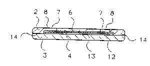
In Figure 12, the channels (6) are made in the reagent carrier
strip (12) and covered over with the flat surface channel carrier
(20); however, the channels (6) can just as well be made in the
channel carrier (20); the reagent carrier strip (12) then clo~es
the channels (6) off by means of a smooth and continuous upper
surface.
.,, ; ~ , . : : ::