Language selection

Search

Patent 2115616 Summary

Third-party information liability

Some of the information on this Web page has been provided by external sources. The Government of Canada is not responsible for the accuracy, reliability or currency of the information supplied by external sources. Users wishing to rely upon this information should consult directly with the source of the information. Content provided by external sources is not subject to official languages, privacy and accessibility requirements.

Claims and Abstract availability

Any discrepancies in the text and image of the Claims and Abstract are due to differing posting times. Text of the Claims and Abstract are posted:

  • At the time the application is open to public inspection;
  • At the time of issue of the patent (grant).
(12) Patent: (11) CA 2115616
(54) English Title: CORNER ASSEMBLY AND FRAME COMPRISING SUCH ASSEMBLY
(54) French Title: ENSEMBLE CORNIERE/GLISSIERE ET CADRE MUNI DE CET ENSEMBLE
Status: Expired and beyond the Period of Reversal
Bibliographic Data
(51) International Patent Classification (IPC):
  • E06B 01/12 (2006.01)
  • E06B 01/36 (2006.01)
  • E06B 09/52 (2006.01)
(72) Inventors :
  • GUILLEMET, GUY (Canada)
(73) Owners :
  • BAY MILLS LTD.
(71) Applicants :
  • BAY MILLS LTD. (Canada)
(74) Agent: SMART & BIGGAR LP
(74) Associate agent:
(45) Issued: 2004-04-20
(22) Filed Date: 1994-02-14
(41) Open to Public Inspection: 1995-03-17
Examination requested: 2001-01-16
Availability of licence: N/A
Dedicated to the Public: N/A
(25) Language of filing: English

Patent Cooperation Treaty (PCT): No

(30) Application Priority Data:
Application No. Country/Territory Date
08/122,887 (United States of America) 1993-09-16

Abstracts

English Abstract


A corner assembly and frame comprising such
assembly is provided, for holding a screen or the
like, in which the corner assembly has a pair of
arms disposed to be connected to frame side members,
preferably by being telescopically received therein,
with a frame generally having such corner assemblies
at corners thereof, for facilitating retaining the
frame assembly, which is a removable assembly,
inside a fixed frame at the periphery of a window.
Each corner assembly includes a slide member carried
in a slideway, which slide member carries a
retaining protrusion extending therefrom, and with
the slide member having a manually engageable
button, movable button, movable longitudinally, to
move the slide member and its protruding button
between two positions, one position of which is an
extended position for the retaining protrusion, and
another position of which is a retracted position
therefor. In the extended position of the retaining
protrusion, the protrusion is adapted to engage
within a recess of a fixed frame member of a window.


Claims

Note: Claims are shown in the official language in which they were submitted.


-7-
CLAIMS:
1. A frame for a screen or the like, comprising a
plurality of side members and a plurality of corner
assemblies; with each such corner assembly comprising a
corner connector having a corner junction and pair of
connector arms disposed at approximately 90° relative to
each other and in telescopic connected relation with a
plurality of side members; with said connector arms being
spaced apart from each other by said corner junction; with
said corner junction including an exterior surface not in
telescopic connected relation with a said side member; with
the corner connector having a slideway therein, disposed
parallel to, and at least partially within one of its said
arms; with a slide member carried in said slideway, in
sliding engagement therewith between extended and retracted
positions therein, with said slide member having a retaining
protrusion extending therefrom, in a direction generally
parallel to said slideway; said retaining protrusion
extending in protruding relation beyond said corner
connector in the extended position of said slide member and
being substantially entirely disposed in retracted relation
within said corner connector in the retracted position of
said slide member; and including a retaining button carried
by said slide member and being adapted to be manually
engaged by a user for moving said slide member between
extended and retracted positions thereof, including an
elongated opening in the corner junction, generally parallel
with said slideway and connecting said slideway with the
exterior of said corner junction, and with said retaining
button extending from said slide member to the exterior of
the corner junction through said opening.
2. The frame of claim 1, including an elongated
opening in the corner connector, generally parallel with

-8-
said slideway and connecting said slideway with the exterior
of said corner connector, and with said retaining button
extending from said slide member to the exterior of the
corner connector through said opening, for traversal of said
retaining button along said opening as said slide member
moves between retracted and extended positions.
3. The frame of claim 1, wherein said corner assembly
is comprised of only the following three separate parts;
a) the corner connector;
b) the slide member; and
c) the button.
4. The frame of claim 2, with said retaining button
having a face and shank; and with the shank extending
through said opening and being carried by said slide member.
5. The frame of claim 4, wherein the face of said
retaining button includes means for facilitating manual
engagement thereof.
6. The frame of claim 1, wherein said corner assembly
is comprised of thermoplastic components.
7. The frame of claim 1, wherein said retaining
protrusion is of unitary construction with said slide
member.
8. The frame of claim 1, including an elongated
opening in the corner connector, generally parallel with
said slideway and connecting said slideway with the exterior
of said corner connector, and with said retaining button
extending from said slide member to the exterior of the
corner connector through said opening, for traversal of said
retaining button along said opening as said slide member

-9-
moves between retracted and extended positions; with said
retaining button having a face and shank; and with the shank
extending through said opening and being carried by said
slide member; wherein the face of said retaining button
includes means for facilitating manual engagement thereof;
wherein said corner assembly is comprised of thermoplastic
components; wherein said corner assembly is comprised of the
following three separate parts;
a) the corner connector;
b) the slide member;
c) the retaining button; and
wherein said retaining protrusion is of unitary construction
with said slide member.
9. A corner assembly for a frame for a screen or the
like, with the assembly comprising a corner connector having
a corner junction and a pair of connector arms disposed at
approximately 90° relative to each other; with said
connector arms being spaced apart from each other by said
corner junction, and with said corner junction including at
least one exterior face, with the corner connector having a
slideway therein disposed parallel to, and at least
partially within one of its said arms; with a slide member
carried in said slideway in sliding engagement therewith,
between extended and retracted positions therein; with said
slide member having a retaining protrusion extending
therefrom, in a direction generally parallel to said
slideway; said protrusion extending in protruding relation
beyond said corner connector in the extended position of
said slide member and being substantially entirely disposed
in retracted relation within said corner connector in the
retracted position of said slide member; and including a

-10-
retaining button carried by said slide member and being
adapted to be manually engaged by a user for moving said
slide member between extended and retracted positions
thereof, including an elongated opening in the exterior face
of the corner junction, generally parallel with said
slideway and connecting said slideway with the exterior of
said corner junction, and with said retaining button
extending from said slide member to the exterior of the
corner junction through said opening.
10. The assembly of claim 9, including an elongated
opening in the corner connector, generally parallel with
said slideway and connecting said slideway with the exterior
of said corner connector, and with said retaining button
extending from said slide member to the exterior of the
corner connector through said opening, for traversal of said
retaining button along said opening as said slide member
moves between retracted and extended positions.
11. The assembly of claim 9, wherein said corner
assembly is comprised of only the following three separate
parts;
a) the corner connector;
b) the slide member; and
c) the retaining button.
12. The assembly of claim 9, with said retaining
button having a face and shank; and with the shank extending
through said opening and being carried by said slide member.
13. The assembly of claim 12, wherein the face of said
retaining button includes means for facilitating manual
engagement thereof.

-11-
14. The assembly of claim 9, wherein said corner
assembly is comprised of thermoplastic components.
15. The assembly of claim 9, wherein said retaining
protrusion is of unitary construction with said slide
member.
16. The assembly of claim 9, including an elongated
opening in the corner connector, generally parallel with
said slideway and connecting said slideway with the exterior
of said corner connector; and with said retaining button
extending from said slide member to the exterior of the
corner connector through said opening, for traversal of said
retaining button along said opening as said slide member
moves between retracted and extended positions; with said
retaining button having a face and shank; and with the shank
extending through said opening and being carried by said
slide member; wherein the face of said retaining button
includes means facilitating manual engagement thereof;
wherein said corner assembly is comprised of thermoplastic
components; wherein said corner assembly is comprised of the
following three separate parts;
a) the corner connector;
b) the slide member;
c) the retaining button; and
wherein said protrusion is of unitary construction with said
slide member.

Description

Note: Descriptions are shown in the official language in which they were submitted.


r-
2i15~~.6
-1 -
CORNER ASSEMBLY AND FRAME
COMPRISING SUCH ASSEN~LY
BACKGROUND OF THE INVENTION
In the art of window manufacture, it is known
to provide windows with fixed frames, in which
movable frames are disposed. The movable frames may
carry screening therein, for ventilation purposes.
It is also known, in the art of window
manufacture, that movable frame assemblies are
disposed within fixed frame assemblies, for raising
or lowering screens or the like, for pivotally
moving screens or the like, for facilitating
placement, cleaning, or for any other purposes
and/or for adjustment of the position of the movable
frame assembly that comprises the screen or the
like, within the fixed frame.
One example of a prior art type of frame corner
bracket is disclosed in U.S. Patent Des. 307,078
dated April 10, 1990, which represents a corner
bracket for holding an insect screen, or the like,
that may be inserted into an exterior frame.
'SHE PRESENT INVENTION
The present invention is directed toward
providing a frame assembly that includes a corner
assembly for an insect screen, or the like, in which
means are provided for efficiently providing a
retaining mechanism for retaining the movable frame
assembly into a fixed frame, for any of various
purposes, such as for securement of the movable
frame in a retained position, for facilitating a
desired position of the movable frame assembly
relative to a fixed frame, etc.

CA 02115616 2003-06-02
60973-646
-la-
The invention provides a frame for a screen or the
like, comprising a plux:~ality of side members and a plurality
of corner assemblies; with each such corner assembly
comprising a corner coxaneector having a corner junction and
pair of connect=or arms disposed at approximately 90°
relative to each other and in telescopic connected relation
with a pluralit:.y of sic~.e members; with said connector arms
being spaced apart from each other by said corner junction;
with said corner junction .including an exterior surface not
in telescopic connectec .relation with a said side member;
with the corner connector having a slideway therein,
disposed paral7_el to, a.nc~ at least partially within one of
its said arms; with a slide member carried in said slideway,
in sliding engagement the=rewith between extended and
retracted positions therein, with said slide member having a
retaining protrusion ex.tendi.ng therefrom, in a direction
generally parallel to said slideway; said retaining
protrusion extending in protruding relation beyond said
corner connector in the extended position of said slide
member and being substantially entirely disposed in
retracted relation within said corner connector in the
retracted position of. said .slide member; and including a
retaining button carried by said slide member and being
adapted to be manually engaged by a user for moving said
slide member between extended and retracted positions
thereof, including an elongated opening in the corner
junction, generally parallel with said slideway and
connecting said slideway with the exterior of said corner
junction, and with said retaining button extending from said
slide member to the exterior of the corner junction through
said opening.
The :invention also provides a corner assembly for
a frame for a screen or the like, with the assembly

CA 02115616 2003-06-02
60973-646
-lb--
comprising a corner connector having a corner junction and a
pair of connector arms disposed at approximately 90°
relative to each other; with said connector arms being
spaced apart from each other by said corner junction, and
with said corner junction including at least one exterior
face, with the corner connector having a slideway therein
disposed paral=_el to, and at :Least partially within one of
its said arms; with a slide member carried in said slideway
in sliding engagement therewith, between extended and
retracted positions there°_:in; wi_th said slide member having a
retaining protrusion extending therefrom, in a direction
generally parallel to said slideway; sa:ici protrusion
extending in protruding relation beyond said corner
connector in the extended position of said slide member and
being substantially entire:ly~ disposed in retracted relation
within said corner connector in the retracted ,position of.
said slide member; and including a retaining button carried
by said slide member and being adapted to be manually
engaged by a u~~er for moving said slide member between
extended and retracted positions thereof, including an
elongated opening .in the exterior face of the corner
junction, generally parallel with said slideway and
connecting said slideway with the exterior of said corner
junction, and with said retaining button extending from raid
slide member to the exterior of the corner junction through
said opening.

~1~5~16
-2-
Accordingly, it is a primary object of this
invention to provide a novel corner assembly and
frame comprising such assembly, in which a frame
assembly for a screen or the like is provided with a
slidable locking mechanism.
It is another object of this invention to
provide a corner assembly for a removable frame, in
accordance with the foregoing object.
It is another object of this invention to
provide an efficient retaining mechanism of the
slide type, for use with a corner assembly for a
movable or removable frame assembly for a screen or
the like.
Other objects and advantages of the present
invention will be readily understood, upon a reading
of the following brief descriptions of the drawing
figures, detailed descriptions of the preferred
embodiments, and the appended claims.
BRTEF DESCR~;PTIONS OF THE DRAWING FIGURES
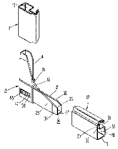
Fig. 1 is a fragmentary, perspective, exploded
view of the corner assembly of this invention and
portions of side members of a movable or removable
frame, to which the corner assembly is connected.
Fig. 2 is a fragmentary front view of a lower
left corner of a movable or removable screen frame
assembly, including a corner assembly, in accordance
with this invention.
Fig. 3~is a horizontal, sectional view taken
through the corner assembly shown in Fig. 2,
generally along the line III-III of Fig. 2, with the
retaining protrusion of the corner assembly being
shown disposed in retaining relation in a portion of
a fixed frame assembly, that in turn, is illustrated
in phantom in Fig. 3.

2115616
-3-
Fig. 4 is a vertical sectional view taken
through the corner assembly of Fig. 2, generally
along the line IV-IV of Fig. 2.
DETAILED DESCRIPTIONS OF THE PREFERRED EMBODIMENTS
Referring now to the drawings in detail,
reference is first made to Fig. 1, wherein the
movable frame assembly that is shown in Fig. 2, is
seen as comprising a pair of side frame members 11
and 12, generally disposed about 90° apart, and a
corner assembly 13.
The corner assembly 13 has a pair of connector
arms 14, 15 extending outwardly from a corner
connector portion 16, generally at 90° relative to
each other as shown, for facilitating telescopic
receipt of the arms 14, 15, into corresponding
channels or other openings 17, 18, respectively, of
the frame side members 11, 12, which telescopic
receipt of such arms 14, 15 is thus shown in the
dotted line showing for the arms in Fig. 2.
The cross-sectional configuration for the frame
side members 11, 12, may be of the roll formed or
extruded U-shaped construction 20, 21 shown for
example, in Fig. 1, for the frame
side member 12, with the channel 18 opening upward,
as shown, for receipt therein of a peripheral bead
22 for a screen 23 (see Fig. 2) therein, as shown.
It will be understood that there will preferably be
four such~frame side members 11, 12, comprising the
periphery of the movable or removable frame 10, with
retaining corner assemblies 13, preferably at each
of the four corners thereof.
Each arm 14, 15 of the corner assembly 13 will
preferably also have a U-shaped configuration 25,
opening into a channel 26, as shown in Fig. 1,

21156.6
-4-
including a base 27, arms 28,30, adapted to be
resiliently received in gripping telescopic relation
within side members 11, 12. In the particular
arrangement shown, the portions 27, 28 and 30 of the
arm 15 are respectively received within zones 31,
32, 33 of frame side member 12 as shown in Fig. 1.
It will be noted that the outer end of each of arm
portions 27, 28 and 30 is chamfered as shown at 34.
It will also be understood that the arm 14 is
constructed generally similar to that of 15, as
shown, for likewise telescopic connection to the
frame side member 11.
At the left end of the U-shaped opening 26 of
the arm 15, and continuing into the interior 35 of
the corner junction 16, is a slideway 36, as shown
in Fig. 4. The slideway 36 houses therein a slide
member 37, movable therein between the full line
position therefor shown in Fig. 3 and the phantom
line position therefor 38, also shown in Fig. 3,
with the slide member 37 being of generally
rectangular configuration, as shown in dotted lines
in Fig. 2.
Fixedly carried on the left end of the slide .
member 37, and preferably unitary therewith, is a
retaining protrusion 38, such that when the slide
member 37 has its right-most end as shown in Fig. 3
in the phantom line position 38 illustrated in Fig.
3, the left-most end 40 of the retaining protrusion
38~is either even with the left-most end 41 of the
corner connector 16, or is slightly sunken (not
shown), relative thereto, such that it does not
protrude outwardly thereof. ,When the slide member
37 is in the full line position therefor shown in
Fig. 3, the retaining protrusion 38 is in the
extended position shown in Fig. 3, adapted to be

2~~~~~~
-5-
engaged within a recess 42 in a fixed frame member
43, preferably disposed about the movable or
removable frame member 10, in which the movable or
removable frame member 10 will preferably be
received.
Alternatively, 'the slide member 37 could be of
multiple-piece construction, such as in the form of
a two-piece snap-in arrangement, not shown herein.
A slot 44 is provided in the slide member 37,
in which a pair of locking tangs 45, 46 of a button
47 are received, in resilient engagement therewith,
as shown in Fig. 3, with the button 47 having a
manually engageable, slightly protruding and/or
knurled outer surface 48, for engagement by
preferably the thumb of a user, for sliding the
slide member 37 within the slideway 36, by engaging
the surface 48 of the button 47 and moving the same
leftward and rightward within its guideway 50 as
shown in Fig. 3.
Thus, it will be seen that the slide member 37
moves parallel with and within the slideway 36, upon
movement of the button 47 within its guideway 50,
also parallel therewith.
It will also be seen that the corner assembly
is preferably constructed of only three components;
namely, the corner connector 16 with its extending
arms 14 and 15 comprising one component, with the
slide member 37 comprising another component, and
with the retaining button 47 comprising the third
component. Alternatively, the corner assembly could
be made of a fewer or greater number of components.
It will also be understood that the device of the
present invention ma.y be constructed such that the
components of the corner assembly are of
thermoplastic construction, which lends itself to

2~1~~16
-6-
ready slidability of the sliding components within
their slideways/guideways; that the corner
assemblies are readily adaptable for insertion into
side frame members that are of any compatible
construction, such as aluminum, steel, vinyl or
other appropriate materials, and which lend
themselves to adaptation to various color schemes,
or the like.
It will further be understood that various
modifications may be made in the details of
constructions, as well as in the use
and operation of the components of the present
invention, all within the spirit and scope of the
invention as defined in the appended claims.

Representative Drawing
A single figure which represents the drawing illustrating the invention.
Administrative Status

2024-08-01:As part of the Next Generation Patents (NGP) transition, the Canadian Patents Database (CPD) now contains a more detailed Event History, which replicates the Event Log of our new back-office solution.

Please note that "Inactive:" events refers to events no longer in use in our new back-office solution.

For a clearer understanding of the status of the application/patent presented on this page, the site Disclaimer , as well as the definitions for Patent , Event History , Maintenance Fee  and Payment History  should be consulted.

Event History

Description Date
Time Limit for Reversal Expired 2011-02-14
Letter Sent 2010-02-15
Inactive: IPC from MCD 2006-03-11
Grant by Issuance 2004-04-20
Inactive: Cover page published 2004-04-19
Inactive: Final fee received 2004-01-14
Pre-grant 2004-01-14
Notice of Allowance is Issued 2003-07-21
Letter Sent 2003-07-21
Inactive: Approved for allowance (AFA) 2003-07-10
Amendment Received - Voluntary Amendment 2003-06-02
Inactive: S.30(2) Rules - Examiner requisition 2002-12-02
Amendment Received - Voluntary Amendment 2001-02-06
Letter Sent 2001-01-26
Inactive: Status info is complete as of Log entry date 2001-01-26
Inactive: Application prosecuted on TS as of Log entry date 2001-01-26
Request for Examination Requirements Determined Compliant 2001-01-16
All Requirements for Examination Determined Compliant 2001-01-16
Application Published (Open to Public Inspection) 1995-03-17

Abandonment History

There is no abandonment history.

Maintenance Fee

The last payment was received on 2004-01-23

Note : If the full payment has not been received on or before the date indicated, a further fee may be required which may be one of the following

  • the reinstatement fee;
  • the late payment fee; or
  • additional fee to reverse deemed expiry.

Patent fees are adjusted on the 1st of January every year. The amounts above are the current amounts if received by December 31 of the current year.
Please refer to the CIPO Patent Fees web page to see all current fee amounts.

Owners on Record

Note: Records showing the ownership history in alphabetical order.

Current Owners on Record
BAY MILLS LTD.
Past Owners on Record
GUY GUILLEMET
Past Owners that do not appear in the "Owners on Record" listing will appear in other documentation within the application.
Documents

To view selected files, please enter reCAPTCHA code :


To view images, click a link in the Document Description column (Temporarily unavailable). To download the documents, select one or more checkboxes in the first column and then click the "Download Selected in PDF format (Zip Archive)" or the "Download Selected as Single PDF" button.

List of published and non-published patent-specific documents on the CPD .

If you have any difficulty accessing content, you can call the Client Service Centre at 1-866-997-1936 or send them an e-mail at CIPO Client Service Centre.

({010=All Documents, 020=As Filed, 030=As Open to Public Inspection, 040=At Issuance, 050=Examination, 060=Incoming Correspondence, 070=Miscellaneous, 080=Outgoing Correspondence, 090=Payment})


Document
Description 
Date
(yyyy-mm-dd) 
Number of pages   Size of Image (KB) 
Representative drawing 1998-02-23 1 13
Claims 2003-06-01 5 222
Representative drawing 2003-07-09 1 7
Description 2003-06-01 8 292
Abstract 1995-05-19 1 27
Claims 1995-05-19 5 504
Drawings 1995-05-19 2 163
Description 1995-05-19 6 610
Drawings 2001-02-05 2 41
Reminder - Request for Examination 2000-10-16 1 116
Acknowledgement of Request for Examination 2001-01-25 1 179
Commissioner's Notice - Application Found Allowable 2003-07-20 1 160
Maintenance Fee Notice 2010-03-28 1 171
Correspondence 1994-03-10 3 86
Correspondence 2004-01-13 1 29
Fees 1997-02-04 1 84
Fees 1996-01-29 1 82