Note: Descriptions are shown in the official language in which they were submitted.
CA 02115655 2003-06-04
' 30465-$
A KING ROLL REELING MACHINE
The present invention relates to a king roll reeling machine for
winding webs of material, in particular of paper or cardboard,
onto spools. Winding machines of this kind are used to
produce winding rollers from webs of material divided by a
lengthwise cut. During the winding process, the winding
rollers lie axially aligned on the two king rolls.
In order to reduce downtimes that result from the need to replace
winding rollers, DE-OS 29 20 707 describes how the web of
material is separated in the roller bed that is formed by the
king rolls by means of a cutter that can be moved upwards through
the gap between the king rolls and incorporates a blade, when the
full winding rollers are ejected. The new start to the web that
is created by this cutting operation is held on the king roll
around which the web passes by a partial vacuum until such time
as a new set of spools has been installed in the roller bed.
WO 92/03366 describes a king roll reeling machine of this type in
which the space that is defined by the king rolls and the winding
rollers is pressurized by means of compressed air. This
pressurization reduces the weight and thus the line load (the
weight per winding roll width) on the two contact lines of the
winding rollers on the king rolls: this has a decisive inference
on the hardness of a winding roller. By reducing this load, it
is possible to wind winding rollers of very great diameter (more
than 800 mm) that are of high winding quality. According to one
embodiment, an air box is arranged in the lower wedge-shaped
space between the king rolls; this air box extends across the
whole working width (the axial length of the king rolls) and
incorporates a compressed air feed line. The air box can be
1
CA 02115655 2003-06-04
30465-8
pivoted downwards from an upper working position, in which
its side surfaces lie against the king rolls, so as to form
a seal, into a position beneath one of the king rolls. This
downward pivoting motion creates space for a separate cutter
that can be moved upwards through the gap between the king
rolls; the web is cut by the blade of this cutter when the
full winding rollers are ejected.
Description of the invention
It is the task of the present invention to improve
a king roll reeling machine of this kind such that the rolls
can be changed in a shorter period of time and such that it
can be so constructed as to save space.
This problem has been solved with a king roll
winding machine for winding webs of material, in particular
webs of paper or cardboard, onto spools - with two king
rolls on which the winding rollers lie during the winding
process, the web of material passing partially around a king
roll and being fed from below through the gap between the
king rolls; - with a cutter to cut the web during a winding
roller change, this incorporating a blade that can be moved
upwards through the gap between the king rolls and into the
roller bed; - with an air box that extends across the whole
working width and incorporates a compressed air feed and
which, arranged in the lower wedge-shaped gap between the
two king rolls, seals the gap between the king rolls, and
which has an air outlet slot that extends across the working
width and is open towards the king rolls; - with a support
rod in the air box, the cutter being secured to the support
rod; and - with an actuating means in the air box
2
CA 02115655 2003-06-04
30465-8
operatively connected to the support rod for selectively
displacing the support rod; whereby the cutter can be moved
up and down and can be raised through the air outlet slot
into its cutting position within the roller bed and lowered
completely into the air box.
The arrangement of a cutter with its blade in the
air box takes up less space than a separate cutter.
Furthermore, the air box does not have to be lowered in
order to carry out a roll change. Lowering is only required
in order to insert a new web or to clear a paper jam. A
roll change can be carried out quicker because the blade of
the cutter can be moved up into its cutting position within
the roller bed without pivoting the air box out of the way
beforehand.
The sub-claims describe preferred and particularly
advantageous embodiments of the present invention.
Brief description of the drawings
The drawings serve to explain the present
invention on the basis of one embodiment that is shown
herein in simple form. These drawings show the following:
2a
2~.1~~~~
Figure 1: a diagrammatic side view of part of a king roll reeling
machine according to the present invention;
Figure 2: a cross-section through the air box with the cutter in
the resting position, in cross-section;
Figure 3: a cross-section in which the blade of the cutter is in
the cutting position.
The way to im,~lement the present invention
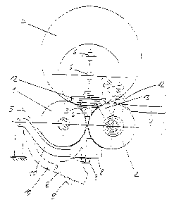
The king roll reeling machine incorporates two driven king rolls
1, 2 between which there is a roller bed 3 in which the winding
rollers 4 lie on the king rolls 1, 2 during the winding process.
The web 5 of material that is divided into individual webs in the
longitudinal direction, and which is preferably a web of paper or
cardboard, is deflected by the king roll 1 and fed from below
through the gap between the king rolls 1, 2 into the king roll
bed 3 and is there wound onto spools 6 that are aligned with each
other. The finished winding rollers ~ are pushed by an ejection
bar (not shown herein) over the king roll 2 and onto a lifting
platform 7, from which the winding rollers 4 are lowered so as to
be unloaded.
In order to reduce the weight of the winding rollers 4 on the
king rolls 1, 2, the space that is defined by the king rolls 1, 2
arid the winding roll 6 can be pressurized with compressed air.
To this end, an air box 8 that incorporates a compressed air
feedline 9 is arranged in the lower wedge-shaped space between
the king rolls 1, 2. This air box extends across the axial
length of the king rolls 1, 2 and its side surfaces that face the
king rolls 1, 2 are curved in the upper part so as to match the
surfaces of the king rolls 1, 2, in order that it can lie against
these so ws to form a seal. Within the curved side surfaces, a
plurality of felt strips that extend axially are installed on the
outside, and these seal the air box 8 relative to the king roll 2
with a minimum of friction. The air box 8 is secured to pivoting
3
CA 02115655 2003-06-04
30465-8
arms 10 that are supported within the framework of the machine.
Thus, it can be lowered from its upper sealing position into a
rest position--shown in Figure 1 with the broken dashed lines--
e.g., in order to insert a new web 5. In the upper sealing
position, its upper part extends as far as the narrowest point
between the two king rolls 1, 2. The upper limiting surface,
which faces the gap between the king rolls incorporates an air
outlet slot 11 that extends at least across the minimal web width
and is formed on the two sides of the machine as a guiding
surface for two sealing elements 12 that are arranged on both
sides of the machine. The shape of the face-end sealing elements
12 is matched to the open cross-sectional surface between the
king rolls 1, 2, its upper section being extended as a
rectangular shape to a point above the line of connection between
the two vertices of the king rolls 1, 2 in order to provide an
adequate sealing surface for winding rollers 4 that are of large
diameter. They are secured in the axial direction--which is to
say transversely to the web 5--so as to be able to slide on the
side pivot arms 13; the axis of pivot of these pivot arms 13
extends on the connecting line between the two king roll axes,
offset somewhat eccentrically to the outside. Thus, the
sealing elements 12 can be pivoted out of the roller bed 3 above
the king roll 2, into a position in which it is possible to move
the side guide heads into the spools 6. The small amount of
eccentricity leads to the fact that the side surfaces of the
sealing elements 12 that face the king rolls 1, 2 move away from
each of the king roll surfaces when they are pivoted outwards,
e.g., in order to permit removal of scraps of paper.
A cutter 14 with a blade 15 is arranged within the air box 8 and
when the air box 8 is in the sealing position, this can be moved
into the roller bed 3 and can be lowered into the air box 8.
Figure 2 shows the blade 15 in the lower position, and Figure 3
shows it in its cutting position within the roller bed 3.
4
2~~5~~5
The blade 15 extends across the whole length of the feed slot 15,
which is to say essentially across the whole width of the
machine. It is secured to the end of a holder 16, which also
extends across the width of the machine and is in the form of a
double-ended lever that is pivoted to its approximate mid-point
at the end of a vertical support rod 18 so as to be rotatable
about an axis 17 that is parallel to the axis of the king rolls.
The support rod 18 is secured to the ends of the piston rods 19
of vertical hydraulic cylinder units, the cylinders of which are
bolted securely to the bottom of the air box 8 and so rest on
this. The cylinders 21 of the pneumatic piston cylinder units
are secured on the lower part of the support rod 18 and the
piston rods 22 of these extend vertically upwards. The end of
the piston rod 22 is articulated to the holder through the lever
23 such that when the piston rods 22 are fully retracted the
hinge points 24 with the holder 16 are off-set somewhat towards
the king roll 2 relative to the hinge points 25 with the piston
rods 22. Because of this, when the piston rods 22 are extended,
the blade 15 moves towards the king roll 1, as is shown in Figure
3. In order that the holder 16 and the lever 23 can be extended,
the support rod 18 has recesses in its upper section, into which
they can be moved. The end of the lever 15 that is remote from
the blade 15 consists of individual tabs; at the end of each
alternate tab, there is either one of the levers 23 or there is a
freely rotatable wheel 26. The axis of rotation for the freely
rotatable wheels 26 is coaxial with the hinge points 24. There
are recesses in the support rod 18 for the wheels 26 that are
offset relative to the levers 23, and the wheels can move in
these. The lower section of the support rod 18 with the piston-
cylinder units 21, 22 is guided in vertical guides 27 that are
arranged in the upper section of the air box 8. On the side of
'the king roll 2, offset in the radial direction relative to the
guides 27, there are other vertical guide rails for the wheels 26
in the upper part of the air box 8, and these determine the
tilted position of the holder 16 while the wheels 26 are still
CA 02115655 2003-06-04
30465-8
within the air box 8. As soon as the wheels 26 leave the air box
upwards, they are guided by the king roll 2 and so determine the
tilting motion of the holder 6 with the blade 15.
In the present example, the whole of the cutter together with its
elevating mechanism is arranged in the air box 8. It is also
possible to secure the cylinder 20 of the piston-cylinder unit
30 outside, on the underside of the air box 8, and then
guide the piston rods 19 through the bottom of the air box 8 in
such a way that they are sealed. This entails the advantage that
the supply lines for the piston-cylinder units 30 can be
arranged outside the air box 8. In the event that it is
necessary for the stability of the air box 8 to arrange vertical
bulkheads within it, the cutter 14 can be divided into individual
segments (e.g., four that are each of a working width of 8 m),
these being arranged in sequence in an axial direction. Each of
these segments will then consist of parts that extend
continuously across the width of the segment (blade 15, holder
16, support rod 18) that are each moved up and down by two side
piston-cylinder units 30 and for which the tilting movement
of the blade 15 is effected by two side piston-cylinder units 31,
that are secured to the lower section of the support rod 18.
As soon as the weight of the winding rollers 4 exceeds a certain
value during the winding process, the face-side sealing elements
12 are tilted into the roller bed 3 and moved axially against the
face sides of the winding rollers 4. The air box 8 is pivoted up
so that the lower wedge-shaped space between the king rolls 1, 2
is sealed off and the sealing elements 12 can rest on its upper
limiting surface. When this is done, they seal off the air
outlet slot 11 outside the area of the winding rollers. Pressure
is generated beneath the winding rollers 8 by introducing
compressed air into the air box 8, and this then reduces the
weight to the desired amount. The compressed air emerges from
the air outlet slot 11 whereas all the parts of the cutter 14,
6
CA 02115655 2003-06-04
30465-8
including the blade 15, are lowered into the air box 8. This
position is shown in Figure 2.
At the end of the winding process, the compressed air supply is
shut off, the face-side sealing elements 12 are pivoted out of
the roller bed 3, and the blade 15 of the cutter 14 is moved into
the cutting position that is shown in Figure 3. To this end,
compressed air is first introduced into the cylinder 21, and this
pre-stresses the pistons 22. A tilting movement of the holder 16
is still not possible because sideways movement of the wheels 26
towards the king roll 2 is prevented by the guide rails. Next,
the piston-cylinder units 30 move the blade 15 upwards. As
soon as the wheels 26 have left the air box 8 they are guided by
the king roll 2. Thus, when the blade 15 moves upwards there is
simultaneously a tilting movement towards the king roll 1 without
the piston-cylinder units 31 having to be controlled. The
height of the support rod 18, the width of the holder 16, and the
travel of the piston 22 are so selected that when the piston rod
19 moves up, the blade 15 moves precisely into its cutting
position within the roller bed 3, at only a slight distance from
the king roll 1 around which the web is wrapped. Next, the full
winding rollers 4 are ejected over the king roll 2, around which
the web is not wrapped, when the web 5 tears on the blade 15.
The new web start that is created in this way is held on the king
roll 1, e.g., by being held against this by suction. Then the
blade 15 is once again lowered into the air box 8. To this end,
first the blade 15 together with the piston-cylinder units 31
are positioned more or less vertically and then the piston-
cylinder units 30 move the support rod 18 with all the parts
that are attached thereto downwards until the blade 15 is within
the air box 8. Once a set of fresh winding spools has been
installed in the roller bed 3 and the newly created web starts
have been secured to these, the king rolls 1, 2 are once again
rotated so that the winding process is recommenced.
7